JCB TM310, TM310S, TM310WM, TM320 Telescopic Wheel Loader Service Manual
690 pages · Publication 9803-9520-9
Added to your cart. View cart
- Models
- TM310, TM310S, TM310WM, TM320
- Serial coverage
- TM310, TM310S, TM310WM from SN 1314700, TM320 from SN 1314700
- Manual type
- Service Manual
- Pages
- 690
- Publication
- 9803-9520-9
- Condition
- Brand new
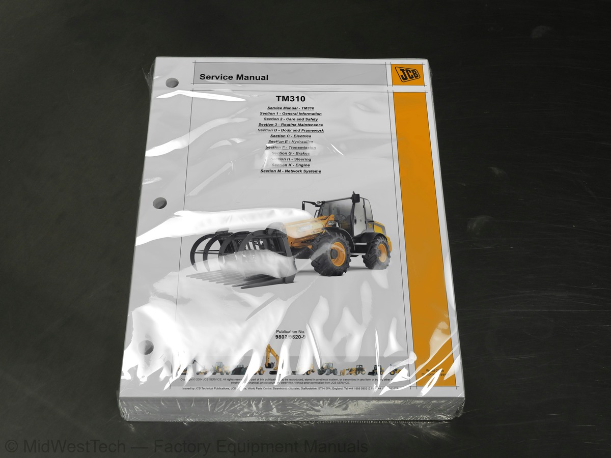
What's inside
From the manual's own table of contents: 6 sections, 391 entries. See sample pages (PDF, 418 KB)
General81 topics
- About this Manual
- Machine Model and Serial Number
- Using the Service Manual
- Section Numbering
- Left Side, Right Side
- Cross References
- Identifying your Machine
- Machine Identification Plate
- Component Identification Plates
- Zinc Plated Fasteners and Dacromet Fasteners
- Introduction
- Bolts and Screws
- Hydraulic Connections
- O' Ring Face Seal System
- Torque Stop' Hose System
- Numerical List
- Tool Detail Reference
- Section B - Body and Framework
- Section C - Electrics
- Section E - Hydraulics
- Section H - Steering
- Section K - Engine
- Sealing and Retaining Compounds
- Colour Coding
- Hydraulic Schematic Colour Codes
- Important Information
- The Operator Manual
- Safety Warnings
- Safety Check List
- Safety - Yours and Others
- General Safety
- Operating Safety
- Maintenance Safety
- Safety Labels
- Safety Label Identification
- Part Numbers and Descriptions
- Service Requirements
- Owner/Operator Support
- Service/Maintenance Agreements
- Initial Service and Inspection
- Fit for Purpose Tests for Lifting Equipment
- Obtaining Replacement Parts
- Health and Safety
- Lubricants
- Battery
- Service Schedules
- How to Use the Service Schedules
- Calendar Equivalents
- Pre-start Cold Checks, Service Points and Fluid Levels
- Functional Test and Final Inspection
- Fluids, Lubricants and Capacities
- Specifications
- Fuel
- Coolant Mixtures
- Tools
- Tool Locations
- Carrying Tools onto the Machine
- Prepare the Machine for Maintenance
- How to Make the Machine Safe (Boom Lowered)
- How to Make the Machine Safe (Boom Lifted)
- Cleaning the Machine
- Preparing the Machine for Cleaning
- Checking for Damage
- Check the Machine Body and Structure
- Check the Tyres
- Check the Seat and Seat Belt
- Check the Electrical Circuits
- Check the Hydraulic Hoses and Fittings
- Checking the ROPS/FOPS Structure
- Greasing
- Preparing the Machine for Greasing
- Boom Pivot Pins
- Centre Pivot and Steering Ram
- Inner and Outer Booms
- Driveshaft Joints
- Access Panels
- Engine Cover
- Heating and Ventilation
- Cleaning the Cab Heater Filter
- Brakes
- Park Brake
Section 3 - Routine Maintenance55 topics
- Electrical System
- Jump Starting the Engine
- Fuses
- Relay Identification
- Engine
- Oil and Filter
- Cooling System
- Front End Accessory Drive (FEAD) Belt
- Engine Crankcase Ventilation
- Engine Air Filter
- Fuel System
- Water Separator and Fuel Filter
- Hydraulic System
- Release the Hydraulic Pressure
- Checking the Fluid Level
- Changing the Filter Element
- Transmission
- Checking the Oil Level
- Changing the Oil and Filter
- Transfer Gearbox
- Axles
- Tyres and Wheels
- Tyre Inflation
- Windscreen Washer
- Fire Extinguisher (if fitted)
- Checking the Fire Extinguisher
- Air Conditioning (Option)
- Load Moment Indicator (LMI)
- Cooling Pack
- Air Conditioning
- Fault Codes
- General Fault Finding
- Diagnostic Tests
- Rivet Nuts
- Fitting Procedure
- Slide Hammer Kit
- Service Checks
- Leak Testing
- Tightening Leaking Hoses
- Refrigerant Charging and Discharging
- Binary Pressure Switch Testing
- Compressor Drive Belt - Adjustment
- Condenser Matrix Cleaning
- ROPS, FOPS Structure - Checks
- Direct Glazing
- Fork Carriage Removal and Replacement
- Removal
- Replacement
- Boom Removal and Replacement
- Dismantling and Assembly
- Dismantling
- Assembly
- Shim Adjustment
- Removal and Replacement
- Transducer
Section B - Body and Framework56 topics
- EMS Unit and Front Console
- Side Switch Panel
- Hose Connections
- Fuel Level Sender
- Internal Components
- Front Floor Mat
- Variflow Pump Access Panel
- Front Blind
- Roof Blind
- Roof Liner
- External Components
- Door Handle Removal and Replacement
- Door Removal and Replacement
- Pressure Switch
- Condenser
- Front Mudguard
- Rear Mudguard
- General Information
- General Electrical Data
- Fuses and Relays
- Secondary Fuses
- Relays
- Primary Fuses
- Fuses and Relays From 1314700
- Overview
- Primary and Secondary Fuses, Ignition Switch and Relays
- Gearbox
- Instrumentation
- SRS and Accessories
- Front Wipe, Rear Wipe and Heater/Air Conditioning
- Front and Rear Worklights, Boom Light and Beacon
- Roadlights
- Auxiliary and Boom Hydraulics
- CAN Overview
- Immobiliser and GPS
- Earthing
- Using a Multimeter
- Measuring DC Voltage
- Measuring Resistance
- Measuring Continuity
- Measuring Frequency
- Testing a Diode or a Diode Wire
- Maintenance
- Testing
- Specific Gravity Testing
- Alternator
- General Description
- Service Precautions
- Charging Circuit Test
- Alternator Charging Test
- Starter Motor
- Starting Circuit Test
- Wire and Harness Number Identification
- Wire Numbers and Functions
- Wiring Harness Repair
- Repair Procedure
Section C - Electrics33 topics
- Removal, Inspection and Replacement
- Dismantle and Assemble
- Renewing the Voltage Regulator and Brushes
- Renewing the Drive Pulley
- Renewing the Brush Gear
- Renewing the Starter Solenoid
- Drawings and Interconnection
- Harnesses
- Main Hydraulic Pump
- Variable Flow
- Auxiliary Pump
- Control Valve Block
- Maximum RPM Cycle Times
- Smooth Ride System (SRS)
- Accumulator
- Flowshare
- Component Location and Identification
- Oil Pump
- Load Sensing
- Pressure Compensation (Flowshare)
- Hydraulic Circuit Operation
- Variable Displacement Pump Operation
- Hydraulic Variable Control System (HVCS)
- Pulse Width Modulation (PWM)
- Flow and Pressure Tests
- Checking Pump Flow
- System Pressures
- Checking the Servo Pilot Pressure
- `Positional Type' Hydraulic Adaptors
- Bleeding the Hydraulic System
- Hand Control Valve
- Dismantling, Inspection and Assembly
- Handling
Section E - Hydraulics66 topics
- Precautions During Use
- Installation
- Caution During Use
- Maintenance, Inspection Points
- Lift Ram
- Displacement Rams
- Extension Ram
- Tilt Ram
- Typical Ram
- Displacement Ram
- Technical Data
- Description
- Hydraulic Schematic
- Fault Finding
- Accumulators
- Charging and Discharging
- Longitudinal Load Moment
- System Overview
- Setting the Volume and Brightness
- Warm Up Procedure
- Daily Functional Check
- Longitudinal Load Moment Control
- Principal of Operation
- Groundworks Mode and Pick and Place Mode
- System Flow Diagram
- LMI Transducers
- Angle Sensors
- LMI Output Signal (PWM)
- Groundworks Mode Enable
- End-Damping
- Diagnostic Fault Codes
- Blink Error Codes
- Test Weight
- LLMI, LLMC Calibration Check
- Machine Stability Check
- System Checks
- Calibration
- Tyre Pressures and Sizes
- Front Axles
- Unit Identification
- Rear Axles
- Powershift Gearboxes
- Transmission Assembly
- PS760 Transmission
- Dual Control Forward, Neutral and Reverse (F/N/R)
- Operation Characteristics
- PS763 and PS766 Powershift Gearboxes
- Component Identification
- Principle of Operation
- Hydraulic and Electrical Operation
- Operation Characteristics - PS760 Gearbox
- Drivepaths - 3 Speed
- Drivepaths - 6 Speed
- Torque Converter
- Lock-Up Torque Converter
- Forward and Reverser Clutch Operation
- Mainshaft, Layshaft and 6-Speed Clutch Operation
- Powershift Gearbox (PS 760 3 Speed)
- Quick Reference
- Wires and Connectors
- Powershift Gearbox (PS766 ECU 2.3 6 Speed)
- Transmission ECU
- ECU Location
- ECU Electrical Connections
- ECU Feeds and Earths
- Lock Up Torque Converter
Section F - Transmission47 topics
- Powershift Gearbox
- Fault Finding Tables
- When Removing
- When Replacing
- Gearbox Integral
- Dismantle, Inspection and Assemble
- Service Brakes
- Bleeding the Braking System
- Bleeding the System
- Hydraulic Pressure Tests
- Standby and Steering Pressure
- Basic Engine Data
- Engine Types
- Engine ECU - SE Engines
- Machine Electrical Interface
- Engine ECU Power-Up
- Cold Start Heater
- Fuel Lift Pump
- Electronic Fault Codes
- Throttle Position Sensor
- Procedure
- What is the Network System?
- CANbus Communications System
- EMS Display
- EMS Set-up
- Connected Devices
- Fault Code Displays
- CAN Enabled Display
- CANbus Connected Computer
- Electronic Monitoring System ECU Fault Codes
- Operator Warnings
- Fault Code Log
- Fault Code List
- Why Use Servicemaster?
- Identify Poor Maintenance
- Access Machine Set Up Data
- Re-Programming ECUs
- Summary
- What is Servicemaster?
- Servicemaster Structure
- How to Set Up Servicemaster
- Install Servicemaster
- Start Servicemaster
- Load the DLA Laptop Driver Software
- Configure the DLA Type and Communications Port
- Check the DLA Firmware File
- Connect Servicemaster to the Machine CANbus
Section M - Network Systems47 topics
- JCB 4.4L Tier 3 SE Diagnostics Tool - User Guide
- Care and Safety
- Connecting 4.4L Tier 3 Diagnostics
- Starting 4.4L Tier 3 Diagnostics
- 4.4L Tier 3 Diagnostics Overview
- Navigating within Diagnostics
- Menu Bar - File Menu
- Menu Bar - Options Menu
- Menu Bar - Window Menu
- Menu Bar - Help Menu
- Start and Stop Buttons
- Status bar
- LED Status Key
- Engine Connector Page
- Machine Connector Page
- Actuator Tests Page
- Fault Codes Page
- ShiftMaster Diagnostics 2.3 - User Guide
- Installing ShiftMaster Diagnostics
- Connecting Shiftmaster Diagnostics
- Starting ShiftMaster Diagnostics
- ShiftMaster Diagnostics Overview
- Navigating within ShiftMaster Diagnostics
- ECU Setup Page
- Dashboard Page
- ECU Status Page
- Torque Converter Lock Up (TCLU) Page
- Solenoid Test Mode Page
- Solenoid Identification Page
- ECU Block Diagram Page
- Connection Problems
- TM310 / TM320 Setup - User Guide
- Installing
- Connection
- Starting TM310 / TM320 Setup
- Navigating within TM310 /TM320 Setup
- Menu Bar - Utilities Menu
- Vehicle Setup
- Options
- Language
- Write
- Read
- Engine Setup - User Guide
- Starting Engine Setup
- Navigating within Engine Setup
- General
- Injector Calibration
Inside this manual
Real pages from this service manual (690 pages). Open the sample pages (PDF, 417 KB)
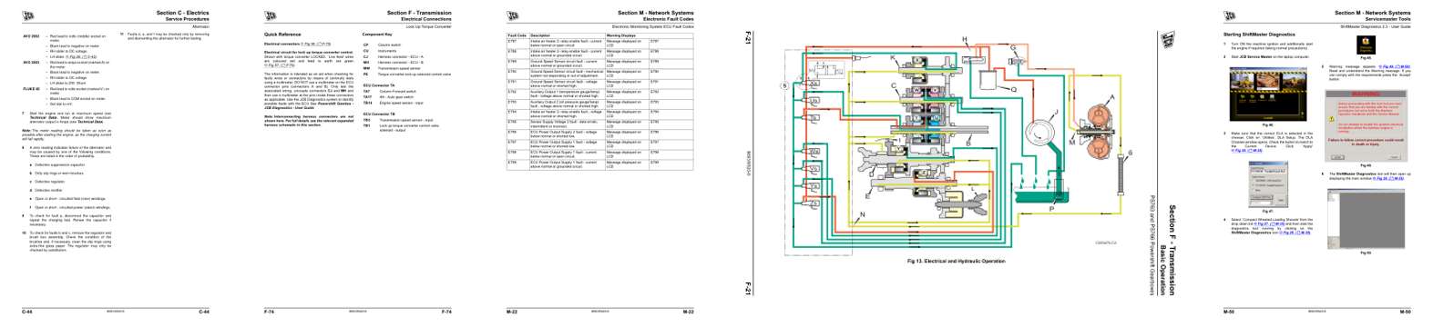
- Specifications, page 280: Section C - Electrics
- Diagram, page 510: Section F - Transmission
- Troubleshooting, page 630: Section M - Network Systems
- Color page, page 457: Section F - Transmission
- Color page, page 658: Section M - Network Systems
This is a service manual
Here's how it compares to the other manual types.
Service manual
Factory repair procedures and technical information such as specifications, troubleshooting, and wiring and hydraulic diagrams, for the models and systems the manual covers. See What's inside for its topics.
Operator's manual
Safe operation, controls, maintenance schedules, lubrication points, inspections, and basic checks. Repair procedures are in the service manual.
Parts manual
Illustrated diagrams with factory part numbers for identifying components and ordering parts. Repair procedures are in the service manual.
Engine service manuals are sometimes sold separately, since certain machine models were offered with more than one engine option.
What it's used for
Factory manual for in-house farm and construction shop use. Straightforward, complete, and easy to follow. It contains the OEM information dealership service departments and parts counters use to diagnose problems, identify components, and perform maintenance or repairs correctly.
Service shops and owner/operators who repair their own equipment
Identifying correct parts and seeing how assemblies come apart and go back together
Keeping equipment running with less downtime
Factory manual, 690 pages
Quantity one is the manual described above.
Fast free USA shipping
Ships in 1 business day.
60-day returns
Free if the mistake is ours. A manual ordered in error must come back unopened in its shrink-wrap; you pay return shipping and a 20% restocking fee applies. Return policy
Binder not included
Manuals over about 300 pages may need a standard 3-ring binder, which you can buy locally to keep the pages organized for shop use.
Other editions and similar models
Questions about model, serial number, engine coverage or contents? Contact us before purchasing and we'll help confirm it's the right manual. Please verify the manual type, machine model, serial number range and engine coverage before purchasing: manuals ordered in error carry a 20% restocking fee (return policy).