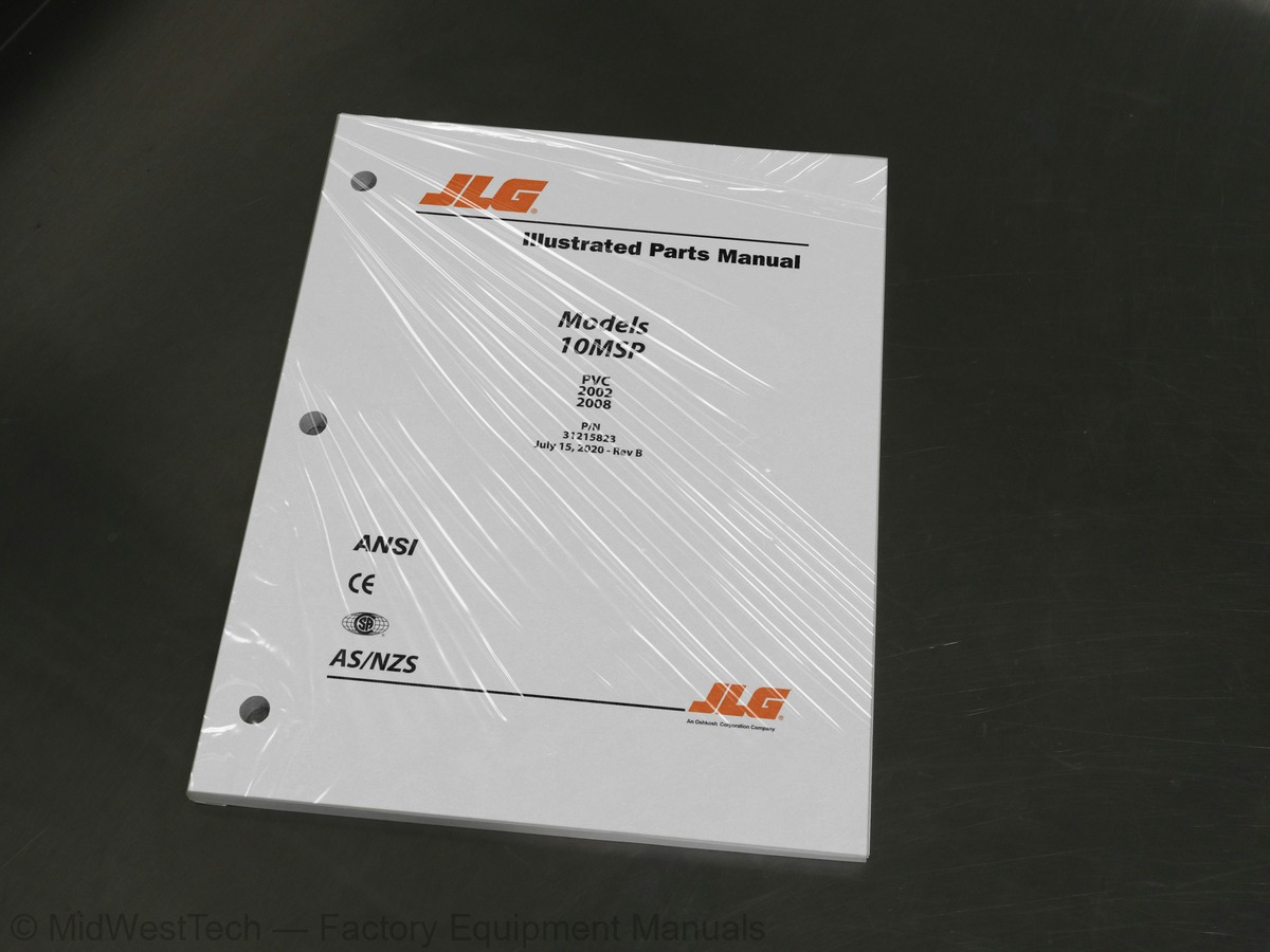
JLG 10MSP Vertical Mast Parts Manual
174 pages · Publication 31215823
Added to your cart. View cart
- Models
- 10MSP
- Manual type
- Parts Manual
- Pages
- 174
- Publication
- 31215823
- Condition
- Brand new
What's inside
From the manual's own table of contents: 28 sections, 80 entries. See sample pages (PDF, 465 KB)
General52 topics
- SECTION 1 - FRAME
- FIGURE 1-1. BASE INSTALLATION
- FIGURE 1-2. DRIVE MOTOR ASSEMBLY
- FIGURE 1-3. COVERS INSTALLATION - MANUAL TRAY
- FIGURE 1-4. COVERS INSTALLATION - POWER TRAY
- FIGURE 1-5. TIE-DOWNS INSTALLATION
- FIGURE 1-6. BUMPERS INSTALLATION (OPTIONAL)
- FIGURE 1-7. GUIDE ROLLER INSTALLATION (OPTIONAL)
- FIGURE 1-8. OBSTRUCTION SENSING PAD INSTALLATION (OPTIONAL)
- FIGURE 1-9. REMOTE MANUAL DESCENT INSTALLATION (OPTIONAL)
- SECTION 2 - CONTROLS
- FIGURE 2-1. PUMP AND MOTOR ASSEMBLY
- FIGURE 2-2. BATTERIES, ALARM AND STROBE INSTALLATION
- FIGURE 2-3. BATTERY CHARGER INSTALLATION (WITHOUT CORD REEL)
- FIGURE 2-4. BATTERY CHARGER INSTALLATION (WITH CORD REEL)
- FIGURE 2-5. CHARGER PLUG INSTALLATION - CUSTOMER SUPPLIED PLUG
- FIGURE 2-6. CHARGER PLUG INSTALLATION - 110V PLUG
- FIGURE 2-7. CHARGER PLUG INSTALLATION - 110V IEC YELLOW PLUG (CE SPECS)
- FIGURE 2-8. CHARGER PLUG INSTALLATION - 220V IEC BLUE PLUG (CE SPECS)
- FIGURE 2-9. CHARGER PLUG INSTALLATION - 220V IEC KEYED GROUND PLUG (CE SPECS)
- FIGURE 2-10. CHARGER PLUG INSTALLATION - 220V IEC POST GROUND PLUG (CE SPECS)
- FIGURE 2-11. CHARGER PLUG INSTALLATION - 220V IEC SIDE GROUND PLUG (CE SPECS)
- FIGURE 2-12. CHARGER PLUG INSTALLATION - 220V (AUSTRALIAN SPECS)
- FIGURE 2-14. GROUND CONTROL AND TRACTION MODULE INSTALLATION (CHINESE AND JAPANESE SPECS)
- FIGURE 2-15. PLATFORM CONTROL BOX ASSEMBLY
- FIGURE 2-16. CONTROLLER ASSEMBLY
- SECTION 3 - MAST
- FIGURE 3-1. MAST INSTALLATION
- FIGURE 3-2. MAST ASSEMBLY
- SECTION 4 - PLATFORM
- FIGURE 4-1. PLATFORM INSTALLATION - WITHOUT GATE LATCH
- FIGURE 4-2. PLATFORM ASSEMBLY - WITHOUT GATE LATCH
- FIGURE 4-3. PLATFORM INSTALLATION - WITH GATE LATCH
- FIGURE 4-4. PLATFORM ASSEMBLY - WITH GATE LATCH
- FIGURE 4-5. TRAY INSTALLATION - MANUAL
- FIGURE 4-6. TRAY ASSEMBLY - MANUAL
- FIGURE 4-7. TRAY INSTALLATION - POWER
- FIGURE 4-8. PUMP ASSEMBLY - POWER TRAY
- FIGURE 4-9. CARGO BELT INSTALLATION (OPTIONAL)
- FIGURE 4-10. FLOORMAT INSTALLATION (OPTIONAL)
- FIGURE 4-11. SCANNER POCKET INSTALLATION (OPTIONAL)
- SECTION 5 - CYLINDER
- FIGURE 5-1. LIFT CYLINDER ASSEMBLY
- FIGURE 5-2. POWER TRAY CYLINDER ASSEMBLY
- SECTION 6 - HYDRAULIC
- FIGURE 6-1. HYDRAULIC SYSTEM INSTALLATION - STANDARD
- FIGURE 6-2. HYDRAULIC SYSTEM INSTALLATION - FIRE RESISTANT
- SECTION 7 - ELECTRICAL
- FIGURE 7-1. CABLES INSTALLATION
- FIGURE 7-2. DRIVE MOTOR HARNESS
- FIGURE 7-3. FOOTSWITCH JUMPER HARNESS
- FIGURE 7-4. GROUND TO PLATFORM HARNESS
Show all 29 sections
Inside this manual
Real pages from this parts manual (174 pages). Open the sample pages (PDF, 464 KB)

- Parts illustration, page 13: SECTION 1 - FRAME
- Parts illustration, page 31: SECTION 2 - CONTROLS
- Parts illustration, page 99: SECTION 5 - CYLINDER
Other manuals for this machine
Save 10% on 2 manuals, 15% on 3 or more. Other manuals for the 10MSP are listed below. Editions cover different serial number ranges: check the serial coverage and tick only the ones that match your machine.
Added to your cart. View cart
This is a parts manual
Here's how it compares to the other manual types.
Service manual
Factory repair procedures and technical information such as specifications, troubleshooting, and wiring and hydraulic diagrams, for the models and systems the manual covers. See What's inside for its topics.
Operator's manual
Safe operation, controls, maintenance schedules, lubrication points, inspections, and basic checks. Repair procedures are in the service manual.
Parts manual
Illustrated diagrams with factory part numbers for identifying components and ordering parts. Repair procedures are in the service manual.
What it's used for
Factory manual for in-house farm and construction shop use. Straightforward, complete, and easy to follow. It contains the OEM information dealership service departments and parts counters use to diagnose problems, identify components, and perform maintenance or repairs correctly.
Service shops and owner/operators who repair their own equipment
Identifying correct parts and seeing how assemblies come apart and go back together
Keeping equipment running with less downtime
Factory manual, 174 pages
Quantity one is the manual described above.
Fast free USA shipping
Ships in 1 business day.
60-day returns
Free if the mistake is ours. A manual ordered in error must come back unopened in its shrink-wrap; you pay return shipping and a 20% restocking fee applies. Return policy
Other editions and similar models
Questions about model, serial number, engine coverage or contents? Contact us before purchasing and we'll help confirm it's the right manual. Please verify the manual type, machine model, serial number range and engine coverage before purchasing: manuals ordered in error carry a 20% restocking fee (return policy).