MidWestTechService, Parts and Operator's Manuals, in stock and ready to ship!
Fast free USA shippingShips in 1 business daySave 10% on 2 manuals, 15% on 3+

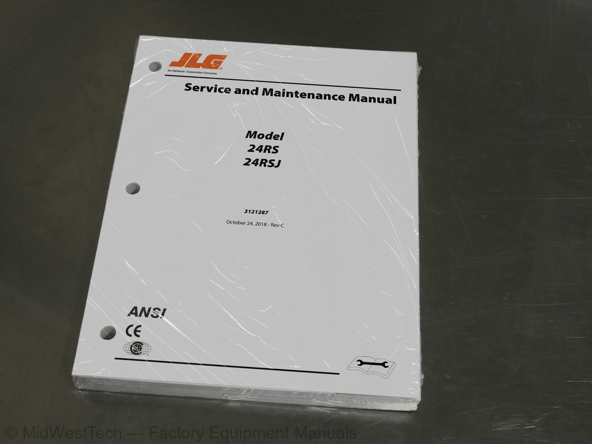
JLG 24RS, 24RSJ Boom Lift Service Manual

302 pages · Publication 3121287

$69.51
Fast free USA shippingShips in 1 business daySave 10% on 2 manuals, 15% on 3 or morePay by credit or debit card or with PayPal. No PayPal account needed.
Models
24RS, 24RSJ
Manual type
Service Manual
Pages
302
Publication
3121287
Condition
Brand new
JLG 24RS, 24RSJ Boom Lift Service Manual, publication 3121287

What's inside

From the manual's own table of contents: 332 sections, 387 entries. See sample pages (PDF, 621 KB)

General
Hydraulic System Safety
Maintenance1 topic
  • Operating Specifications
Dimensional Data
Capacities
Tires
Engine Data
Hydraulic Oil
Major Component Weights3 topics
  • Function Speeds
  • Operator Maintenance
  • Machine Preparation, Inspection, and Maintenance
Preparation, Inspection, and Maintenance
Pre-Start Inspection
Pre-Delivery Inspection and Frequent Inspection
Annual Machine Inspection
Preventative Maintenance1 topic
  • Service and Guidelines
Safety and Workmanship
Cleanliness
Components Removal and Installation
Component Disassembly and Reassembly
Pressure-Fit Parts
Bearings
Gaskets
Bolt Usage and Torque Application
Hydraulic Lines and Electrical Wiring
Hydraulic System
Show all 332 sections
Lubrication
Battery
Lubrication and Servicing1 topic
  • Lubrication and Information
Changing Hydraulic Oil
Lubrication Specifications1 topic
  • Cylinder Drift Test
Theory
Cylinder Leakage Test
Cylinder Thermal Drift2 topics
  • Pins and Composite Bearing Repair Guidelines
  • Welding on JLG Equipment
Do the Following When Welding on JLG Equipment
Do NOT Do the Following When Welding on JLG Equipment1 topic
  • Tires and Wheels
Tire Replacement
Wheel and Tire Replacement
Wheel Installation3 topics
  • Drive Orientation System
  • Drive System
  • Steer Cylinder
Removal
Installation2 topics
  • Drive Hub
  • Drive Motor
Disassembly
End Cover Disassembly
Cleaning
Measuring And Replacement
Assembly
Assembly of End Cover1 topic
  • Swing Drive Hub
Tightening and Torquing Bolts
Brake Test
Roll and Leak Test2 topics
  • Procedure for Setting Swing Gear backlash
  • Swing Bearing
Wear Tolerance
Turntable/Swing Bearing Removal
Swing Bearing Torque Values6 topics
  • Chassis Tilt Indicator System
  • Engine Installation
  • Cold Start System
  • Engine Operating States
  • Engine Start Conditions
  • Engine RPM Levels
Engine Stop RPM
Idle RPM
Cold Idle RPM
Mid Engine RPM
High Engine RPM
Generator RPM1 topic
  • Engine Controls
Alternator Excitation
Glow Plugs
Ambient Air Temperature Sensor7 topics
  • Deutz EMR 2
  • Auxiliary Pump
  • Counterweight
  • Platform Control Enable System
  • Function Speed Control System
  • Transport Position Sensing System
  • Boom Telescope Speed
Extend Function
Retract Function5 topics
  • Beyond Transport Position - Drive Speed Cutback System
  • Drive/Steer – Boom Function Cutout System (Optional)
  • Emergency Descent System
  • Platform Load Sensing System (Japan)
  • Platform
Platform Support Removal
Platform Support Installation1 topic
  • Main Boom
Dissassembly4 topics
  • Lower Boom
  • Telescope Cylinder
  • Hose Adjustment Procedure
  • Skyguard
Operation
Functional Test
Diagnostic & Troubleshooting1 topic
  • Lubricating O-Rings in the Hydraulic System
Cup and Brush
Dip Method
Spray Method
Brush-on Method1 topic
  • Hydraulic Cylinders
Platform Slave Level Cylinder
Master Cylinder
Steer Cylinder
Lift Cylinder
Telescope Cylinder1 topic
  • Sauer Danfoss Pump
New Pump Startup Procedure
Troubleshooting
General Adjustment Practices
Charge Pressure Relief Valve Adjustment
Pressure Limiter Adjustments
Engaging the Bypass Function
Displacement Limiter Adjustment
Control Neutral Adjustment
Mechanical Neutral Adjustment
Standard Procedures, Removing the Pump
Electric Control Module
Control Solenoids
Shaft Seal, Roller Bearing and Shaft Replacement
Charge Pump
Charge Check / HPRV
Charge Pressure Relief Valve
Pressure Limiter Valve Replacement3 topics
  • Hydraulic Drive Pump Pre-fill Procedure
  • Pressure Setting Procedure
  • JLG Control System Analyzer Kit Instructions
Introduction2 topics
  • Analyzer Menu Structure
  • Using the Hand Held Analyzer
To Connect the JLG Control System Analyzer
Using the Analyzer
Changing the Access Level of the Hand Held Analyzer
Adjusting Parameters Using the Hand Held Analyzer
Machine Setup
Level Vehicle Description3 topics
  • System Fault Messages
  • General
  • Multimeter Basics
Grounding
Backprobing
Min/Max
Polarity
Scale
Voltage Measurement
Resistance Measurement
Continuity Measurement
Current Measurement1 topic
  • Applying Silicone Dielectric Compound to Electrical Connections
Installation of Dielectric Grease
Deutsch HD, DT, DTM, DRC Series
AMP Seal
AMP Mate-N-Lok
DIN Connectors
Exclusions
Brad Harrison / Phoenix Contact M12
AMP Junior Timer
Sealed Enclosures
MIL-C-5015 Spec Connectors
MOLEX CMC Series Connectors1 topic
  • Electrical Schematics
Maintenance and Lubrication Diagram
Torque Chart (SAE Fasteners - Sheet 1 of 5)
Torque Chart (SAE Fasteners - Sheet 2 of 5)
Torque Chart (SAE Fasteners - Sheet 3 of 5)
Torque Chart (METRIC Fasteners - Sheet 4 of 5)
Torque Chart (METRIC Fasteners - Sheet 5 of 5)
Hydraulic Oil Operation Chart
Engine Oil Operation Chart
Steering Hydraulic Lines
Drive Hub/Motor Installation
Front Drive/Steer Circuit
Rear Drive Circuit
Axle Hosing
Drive Motor
Swing Motor Disassembly
Motor Disassembly
Input Brake Disassembly
Main Disassembly
Housing Shaft Disassembly
Carrier Disassembly
Carrier Subassembly
Housing Shaft Subassembly
Main Assembly
Timing Marks
Input Brake Assembly
Swing Motor Assembly
Motor Control Valve
Swing Drive Assembly
Bearing Cone Press Tool -T144566
Bearing Cone Pressing Tool - T145741
Bearing Cup Pressing Tool - T149013
Locknut Wrench Tool - T151047
Bearing Cup Pressing Tool - T155291
Seal Press Tool - T175741
Leak Test Adapter Plate Tool - T201746
Swing Drive Test Plate Tool - T187845
Swing Bearing Wear Tolerance - Dial Indicator Placement
Swing Bearing Tolerance Boom Placement - Sheet 1 of 2
Swing Bearing Tolerance Boom Placement - Sheet 2 of 2
Swing Bearing Ramoval (24RS)
Swing Bearing Ramoval (24RSJ)
Chassis/Turntable Hose Routing - Sheet 1 of 2
Chassis/Turntable Hose Routing - Sheet 2 of 2
Swing Bearing Installation
Swing Bearing Torque Sequence
Engine Installation
Engine Operating State Diagram
Alternator Schematic
EMR 2 Engine Side Equipment
Deutz EMR 2 Troubleshooting Flow Chart
Deutz EMR 2 Vehicle Side Connection Diagram
Deutz EMR 2 Engine Side Connection Diagram - Sheet 1 of 2
Deutz EMR 2 Engine Side Connection Diagram - Sheet 2 of 2
EMR 2 Engine Plug Pin Identification
EMR 2 Vehicle Plug Pin Identification
EMR2 Fault Codes - Sheet 1 of 5
EMR2 Fault Codes - Sheet 2 of 5
EMR2 Fault Codes - Sheet 3 of 5
EMR2 Fault Codes - Sheet 4 of 5
EMR2 Fault Codes - Sheet 5 of 5
Auxiliary Pump Hosing and Installation
Cables and Clamps Installation - Sheet 1 of 4
Cables and Clamps Installation - Sheet 2 of 4
Cables and Clamps Installation - Sheet 3 of 4
Cables and Clamps Installation - Sheet 4 of 4
Counterweight Bolt Torque
Location of Components Platform Support
Platform Support Torque Values (Without LSS and 4 Cell LSS)
Block to Set the Upright On
Lift Cylinder Hydraulic Lines
Powertrack Hosing
Tower Boom Hosing - Sheet 1 of 2
Tower Boom Hosing - Sheet 2 of 2
Boom Proximity Sensor
Telescope Cylinder Hydraulic Lines
Hose Adjustment - Figure 1
Hose Adjustment - Figure 2
Hose Adjustment - Figure 3
Hose Adjustment - Figure 4
Hose Adjustment - Figure 5
Powertrack Installation
Skyguard
Slave Level Head Assembly
Master Cylinder Head Assembly
Master Cylinder Piston Assembly
Master Cylinder (24RS)
Master Cylinder (24RSJ)
Steer Cylinder Head Assembly
Steer Cylinder Piston Assembly
Lift Cylinder Head Assembly
Lift Cylinder Piston Assembly
Telescope Cylinder Valve Block
Main Hydraulic Valve - Sheet 1 of 3
Main Hydraulic Valve - Sheet 2 of 3
Main Hydraulic Valve - Sheet 3 of 3
Main Hydraulic Valve Schematic
Flow Divider Valve - Sheet 1 of 2
Flow Divider Valve - Sheet 2 of 2
Hydraulic Oil Tank - Sheet 1 of 3
Hydraulic Oil Tank - Sheet 2 of 3
Hydraulic Oil Tank - Sheet 3 of 3
Filter Location
Main Valve Circuit - Sheet 1 of 2
Main Valve Circuit - Sheet 2 of 2
Hose Routing - Sheet 1 of 3
Hose Routing - Sheet 2 of 3
Hose Routing - Sheet 3 of 3
Charge Pressure Adjustment
Pressure Limiter Adjustment
Pressure Limiter Valve Adjustment
Control Adustment
Neutral Adjustment (Bottom View)
Servo Adjustment
Proper Screen Orientation
Control Module Removal/Installation
Shaft Assembly
Positioning Seal in Seal Carrier
Charge Pump Removal/Installation
Torque Sequence
Auxiliary Pads
High Pressure Relief Valves
Pressure Limiter
Fasteners and Plugs - Sheet 1 of 2
Fasteners and Plugs - Sheet 2 of 2
Hand Held Analyzer
Control Module Location
Ground Module - Sheet 1 of 3
Ground Module - Sheet 2 of 3
Ground Module - Sheet 3 of 3
Platform Module - Sheet 1 of 2
Platform Module - Sheet 2 of 2
Analyzer Top Level Menu (Software Version P2.7)
Analyzer Diagnostics Menu - Sheet 1 of 3(Software Version P2.7)
Analyzer Diagnostics Menu - Sheet 2 of 3(Software Version P2.7)
Analyzer Diagnostics Menu - Sheet 3 of 3(Software Version P2.7)
Analyzer Personalities Menu - Sheet 1 of 3 (Software Version P2.7)
Analyzer Personalities Menu - Sheet 2 of 3 (Software Version P2.7)
Analyzer Personalities Menu - Sheet 3 of 3 (Software Version P2.7)
Analyzer Machine Setup Menu (Software Version P2.7)
Analyzer Calibrations Menu (Software Version P2.7)
Voltage Measurement (DC)
Current Measurement (DC)
Application to Male Contacts
Use of Seal Plugs
Brad-Harrison M12
Phoenix Contact M12
Electrical System Installation (24RS) - Sheet 1 of 7
Electrical System Installation (24RS) - Sheet 2 of 7
Electrical System Installation (24RS) - Sheet 3 of 7
Electrical System Installation (24RS) - Sheet 4 of 7
Electrical System Installation (24RS) - Sheet 5 of 7
Electrical System Installation (24RS) - Sheet 6 of 7
Electrical System Installation (24RS) - Sheet 7 of 7
Electrical System Installation (24RSJ) - Sheet 1of 7
Electrical System Installation (24RSJ) - Sheet 2 of 7
Electrical System Installation (24RSJ) - Sheet 3 of 7
Electrical System Installation (24RSJ) - Sheet 4 of 7
Electrical System Installation (24RSJ) - Sheet 5 of 7
Electrical System Installation (24RSJ) - Sheet 6 of 7
Electrical System Installation (24RSJ) - Sheet 7 of 7
Electrical Schematic - Sheet 1 of 14
Electrical Schematic - Sheet 2 of 14
Electrical Schematic - Sheet 3 of 14
Electrical Schematic - Sheet 4 of 14
Electrical Schematic - Sheet 5 of 14
Electrical Schematic - Sheet 6 of 14
Electrical Schematic - Sheet 7 of 14
Electrical Schematic - Sheet 8 of 14
Electrical Schematic - Sheet 9 of 14
Electrical Schematic - Sheet 10 of 14
Electrical Schematic - Sheet 11 of 14
Electrical Schematic - Sheet 12 of 14
Electrical Schematic - Sheet 13 of 14
Electrical Schematic - Sheet 14 of 14
Hydraulic Schematic - Sheet 1 of 2
Hydraulic Schematic - Sheet 2 of 2
Operating Specifications
Critical Stability Weights
Machine Orientation When Performing Speed Test
Machine Model Adjustment Speeds
Inspection and Maintenance
Cylinder Drift
Inspection and Preventive Maintenance Schedule
Wheel Torque Chart
Drive System Mode Chart
Swing Brake Chart
Engine RPM Levels
Glow Plug Conditions
Hose Pull Order
SkyGuard Function Table
Cartridge Torque Values
Coil Torque Values
Electrical Troubleshooting
System Operating Hot
Transmission Operates Normally in One Direction Only
System Does Not Operate in Either Direction
System Noise or Vibration
Neutral Difficult or Impossible to Find
Sluggish System Response
Charge Pressure Ranges
Pressure Limiter Settings
Displacement Limiter Adjustment Data
Cover Screw Torque
Fastener Size and Torque Chart
Plug Size and Torque Chart
Analyzer Abbreviations
Machine Configuration Programing Information (Software Version P2.7)
Machine Configuration Programming Settings (Software Version P2.7)
Fault Code List
Fault Code Troubleshooting Information
Overload Variations

Inside this manual

Real pages from this service manual (302 pages). Open the sample pages (PDF, 618 KB)

Sample pages from the JLG 24RS, 24RSJ Boom Lift Service Manual: Specifications, Troubleshooting, Diagram, Color page, Color page
  • Specifications, page 15: SECTION 1 - SPECIFICATIONS
  • Troubleshooting, page 235: SECTION 6 - JLG CONTROL SYSTEM
  • Diagram, page 283: SECTION 7 - BASIC ELECTRICAL INFORMATION & SCHEMATICS
  • Color page, page 135: SECTION 4 - BOOM & PLATFORM
  • Color page, page 87: SECTION 3 - CHASSIS & TURNTABLE

Other manuals for this machine

Save 10% on 2 manuals, 15% on 3 or more. Other manuals for the 24RS, 24RSJ are listed below. Editions cover different serial number ranges: check the serial coverage and tick only the ones that match your machine.

This manual: Service Manual 3121287$69.51
Other manuals for the 24RS, 24RSJ

Parts manuals

Details

This is a service manual

Here's how it compares to the other manual types.

This manual

Service manual

Factory repair procedures and technical information such as specifications, troubleshooting, and wiring and hydraulic diagrams, for the models and systems the manual covers. See What's inside for its topics.

Operator's manual

Safe operation, controls, maintenance schedules, lubrication points, inspections, and basic checks. Repair procedures are in the service manual.

Parts manual

Illustrated diagrams with factory part numbers for identifying components and ordering parts. Repair procedures are in the service manual.

Engine service manuals are sometimes sold separately, since certain machine models were offered with more than one engine option.

What it's used for

Factory manual for in-house farm and construction shop use. Straightforward, complete, and easy to follow. It contains the OEM information dealership service departments and parts counters use to diagnose problems, identify components, and perform maintenance or repairs correctly.

Service shops and owner/operators who repair their own equipment

Identifying correct parts and seeing how assemblies come apart and go back together

Keeping equipment running with less downtime

Factory manual, 302 pages

Quantity one is the manual described above.

Fast free USA shipping

Ships in 1 business day.

60-day returns

Free if the mistake is ours. A manual ordered in error must come back unopened in its shrink-wrap; you pay return shipping and a 20% restocking fee applies. Return policy

Binder not included

Manuals over about 300 pages may need a standard 3-ring binder, which you can buy locally to keep the pages organized for shop use.

Questions about model, serial number, engine coverage or contents? Contact us before purchasing and we'll help confirm it's the right manual. Please verify the manual type, machine model, serial number range and engine coverage before purchasing: manuals ordered in error carry a 20% restocking fee (return policy).