MidWestTechService, Parts and Operator's Manuals, in stock and ready to ship!
Fast free USA shippingShips in 1 business daySave 10% on 2 manuals, 15% on 3+

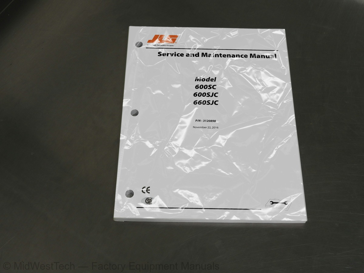
JLG 600SC, 600SJC, 660SJC Boom Lift Service Manual

186 pages · Publication 3120898

$69.81
Fast free USA shippingShips in 1 business daySave 10% on 2 manuals, 15% on 3 or morePay by credit or debit card or with PayPal. No PayPal account needed.
Models
600SC, 600SJC, 660SJC
Serial coverage
Prior to 0300074785
Manual type
Service Manual
Pages
186
Publication
3120898
Condition
Brand new
JLG 600SC, 600SJC, 660SJC Boom Lift Service Manual, publication 3120898

What's inside

From the manual's own table of contents: 233 sections, 288 entries. See sample pages (PDF, 486 KB)

General
Hydraulic System Safety
Maintenance1 topic
  • Capacities
Fuel Tank
Hydraulic Oil Tank
Hydraulic System (Including Tank)
Engine Crankcase1 topic
  • Component Data
Engine - Diesel (Liquid-Cooled)
Swing System
Auxiliary Power Pump1 topic
  • Performance Data
Turning Radius (Outside)
Turning Radius (Inside)
Boom Elevation
Machine Weight approximately
Machine Height (Stowed)
Machine Length (Stowed)
Machine Width1 topic
  • Function Speeds
Machine Orientation When Doing Speed Tests
Test Notes2 topics
  • Torque Requirements
  • Lubrication
Deutz F4M1011F Engine
Hydraulic Oil
Lubrication Specifications6 topics
  • Pressure Settings
  • Cylinder Specifications
  • Major Component Weights
  • Critical Stability Weights
  • Serial Number Locations
  • Machine Preparation, Inspection, and Maintenance
Preparation, Inspection, and Maintenance
Pre-Start Inspection
Show all 233 sections
Pre-Delivery Inspection and Frequent Inspection
Annual Machine Inspection
Preventative Maintenance1 topic
  • Service and Guidelines
Safety and Workmanship
Cleanliness
Components Removal and Installation
Component Disassembly and Reassembly
Pressure-Fit Parts
Bearings
Gaskets
Bolt Usage and Torque Application
Hydraulic Lines and Electrical Wiring
Hydraulic System
Lubrication
Battery
Lubrication and Servicing1 topic
  • Lubrication and Information
Changing Hydraulic Oil1 topic
  • Cylinder Drift Test
Platform Drift
Cylinder Drift2 topics
  • Pins and Composite Bearing Repair Guidelines
  • Tilt Alarm Switch
Manual Adjustment1 topic
  • Throttle Checks and Adjustments - Deutz
Procedure
Controller Status
Failure Modes1 topic
  • Swing Hub
Adjustment Procedures1 topic
  • Swing Bearing
Turntable Bearing Mounting Bolt Condition Check
Wear Tolerance
Swing Bearing Replacement
Swing Bearing Torque Values1 topic
  • Swing Brake - Mico
Disassembly
Inspection
Assembly1 topic
  • Platform
Platform Sections Replacement1 topic
  • Boom Rope Torquing Procedures
Torque Procedures1 topic
  • Wear Pads
Main Boom1 topic
  • Wire Rope
Three Month Inspection
Year or 7000 Hour Replacement
Additional Replacement Criteria1 topic
  • Boom Maintenance
Removal
Disassembly of Boom Sections
Installation5 topics
  • Articulating Jib Boom
  • Limit Switch Adjustment
  • Rotator - Helac
  • Foot Switch Adjustment
  • SUPERFLEX Controller
System Overview
System Elements
General Description
SUPERFLEX Terminal Identification
SUPERFLEX Terminal Assignments
Setup and Tuning
How to Perform the Normal-Active Tuning Process
How to make Bench-Static Adjustments
Troubleshooting
How To Troubleshoot the SUPERFLEX Controller
How to Troubleshoot the Digisensor
Important Reminders
Crawler Tracking Adjustments
Drive & Steer Function Check
Superflex Inputs And Outputs1 topic
  • Cylinders - Theory of Operation
Systems Incorporating Double Acting Cylinders
Systems Incorporating Holding Valves1 topic
  • Valves - Theory of Operation
Solenoid Control Valve - Rexroth
Relief Valves1 topic
  • Cylinder Checking Procedure
Cylinders Without Counterbalance Valves - Master Cylinder and Steer Cylinder
Cylinders With Single Counterbalance Valve
Cylinders With Dual Counterbalance Valves1 topic
  • Cylinder Repair
Cleaning and Inspection1 topic
  • Cylinder Removal and Installation
Main Boom Telescope Cylinder Removal
Main Boom Telescope Cylinder Installation
Main Boom Lift Cylinder Removal
Main Boom Lift Cylinder Installation1 topic
  • Pressure Setting Procedures
Main Relief, Steer, Swing and Lift Down
Platform Level
Articulating Jib Boom (If Equipped)5 topics
  • Hydraulic Pump W/hayes Pump Drive Coupling Lubrication
  • Hydraulic Component Start-Up Procedures and recommendations
  • Track Carrier Roller
  • Track Roller
  • Track
Separate
Connect1 topic
  • Front Idler and Recoil Spring
Front Idler Disassembly
Front Idler Assembly
Recoil Spring Disassembly
Recoil Spring Assembly4 topics
  • Track Adjuster
  • Final Drive Sprocket
  • Travel Brake Valve
  • Travel Motor
Installation Procedure1 topic
  • Final Drive
Final Drive Oil - Change
Final Drive Oil Level Check2 topics
  • Swivel
  • Towing Information
Towing the Machine
Final Drive Sun Gear Removal1 topic
  • Track Adjustment - Adjust
Measuring Track Tension
Tightening the Track
Loosening the Track
Track Adjustment - Inspect4 topics
  • Undercarriage- Check
  • General
  • Troubleshooting
  • Hydraulic Circuit Checks
Serial Number Locations
Lubrication Point Location
Torque Chart
Tilt Switch Adjustment
Addco Adjustments
Swing Torque Hub Adjustment
Swing Bearing Bolt Feeler Gauge Check
Swing Bearing Tolerance Measuring Point
Swing Bearing Tolerance Boom Placement
Swing Bearing Torque Sequence
Swing Brake Assembly (Mico)
Platform Section Replacement
Dimensions of Boom Sections
Clamping Wire Ropes
Location and Thickness of Wear Pads
Location of Components - Platform Support
Location of Components - Rotator and Leveling Cylinder
Location of Components - Boom Powertrack
Boom Assembly Cutaway - S Models - Sheet 1 of 3
Boom Assembly Cutaway - S Models - Sheet 2 of 3
Boom Assembly Cutaway - S Models - Sheet 3 of 3
Disassembly of Sheave Assembly
Disassembly Wire Rope Routing Procedure
Dimension of Sheaves When New
Routing Installation of Retract Wire Ropes
Reassembly of Components - Boom Powertrack Assembly
Boom Powertrack Installation
Location of Components - Articulating Jib Boom
Limit Switches Adjustments
Removing Portion of End Cap
Heating Setscrew
Removing Setscrew
Removing End Cap
Rotator Assembly (Helac)
Removing Shaft from Housing
Removing Sleeve from Housing
Actuator Timing
Wiring Diagram - Single Coil Uni-Directional Flow Control Valve - 1 Axis
Controller Pattern
Calibration Flow Diagram
Testing the SUPERFLEX
Digisensor Troubleshooting
Typical SUPERFLEX System Wiring Diagram
OPTIMIZER Keypad
Cylinder Barrel Support
Cap Screw Removal
Cylinder Rod Support
Tapered Bushing Removal
Gar-Max Bearing Installation
Rod Seal Installation
Poly-Pak Piston Seal Installation
Wiper Seal Installation
Installation of Head Seal Kit
Piston Seal Kit Installation
Tapered Bushing Installation
Seating the Tapered Bearing
Rod Assembly Installation
Boom Positioning and Support, Cylinder Repair
Articulating Jib Boom Pressure Adjustments
Main Control Valve Pressure Adjustments - Sheet 1 of 2
Main Control Valve Pressure Adjustments - Sheet 2 of 2
Location of Components - Main Control Valve (Sheet 1)
Location of Components - Main Control Valve (Sheet 2)
Undercarriage Components
Track Carrier Roller - Exploded View
Track Carrier Roller
Track Roller - Exploded View
Track Roller
Track Link Assembly
Track Shoe
Track Adjuster
Travel Motor
Final Drive
Tooling (J)
Swivel Assembly
Electrical Components Installation - Sheet 1
Electrical Components Installation - Sheet 2
Electrical Schematic - Deutz or Isuzu - Sheet 1 of 2
Electrical Schematic - Deutz or Isuzu - Sheet 2 of 2
Electrical Schematic - Australian w/Deutz or Isuzu - Sheet 1 of 2
Electrical Schematic - Australian w/Deutz or Isuzu - Sheet 2 of 2
Hydraulic Schematic - Sheet 1 of 4
Hydraulic Schematic - Sheet 2 of 4
Hydraulic Schematic - Sheet 3 of 4
Hydraulic Schematic - Sheet 4 of 4
Hydraulic Schematic w/GFT24 Drive - Sheet 1 of 4
Hydraulic Schematic w/GFT24 Drive - Sheet 2 of 4
Hydraulic Schematic w/GFT24 Drive - Sheet 3 of 4
Hydraulic Schematic w/GFT24 Drive - Sheet 4 of 4
Function Speeds (In Seconds)
Torque Requirements
Mobil DTE 13M Specs
Cylinder Specifications
Major Component Weights
Critical Stability Weights
Lubrication Chart
Inspection and Maintenance
Inspection and Preventive Maintenance Schedule
Position Controller Truth Table
Adjusting Threshold
Adjustment Values
Factory Defaults
Cylinder Head and Tapered Bushing Torque Specifications
Holding Valve Torque Specifications
Track Carrier Roller Required Tools - Removal and Installation
Track Carrier Roller Required Tools - Assembly
Track Roller Required Tools - Removal
Track Roller Required Tools - Assembly
Track Required Tools - Separate
Track Required Tools - Connect
Front Idler Required Tools - Assembly
Recoil Spring Required Tools - Disassembly
Recoil Spring Required Tools - Assembly
Track Adjuster Required Tools - Assembly
Final Drive Sprocket Required Tools - Removal
Final Drive Sprocket Required Tools - Installation
Travel Motor Required Tools - Removal
Travel Motor Required Tools - Disassembly
Travel Motor Required Tools - Assembly
Travel Motor Required Tools - Installation
Final Drive Required Tools - Removal
Final Drive Required Tools - Disassembly
Final Drive Required Tools - Assembly
Final Drive Required Tools - Installation

Inside this manual

Real pages from this service manual (186 pages). Open the sample pages (PDF, 485 KB)
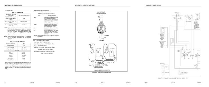
Sample pages from the JLG 600SC, 600SJC, 660SJC Boom Lift Service Manual: Specifications, Troubleshooting, Diagram
  • Specifications, page 16: SECTION 1 - SPECIFICATIONS
  • Troubleshooting, page 68: Figure 4-32. Digisensor Troubleshooting
  • Diagram, page 180: SECTION 7 - SCHEMATICS

Other manuals for this machine

Save 10% on 2 manuals, 15% on 3 or more. Other manuals are listed below. Editions cover different serial number ranges: check the serial coverage and tick only the ones that match your machine.

This manual: Service Manual 3120898$69.81
Other manuals for the 600SC

Parts manuals

Details
Details
Details
Details
Details

This is a service manual

Here's how it compares to the other manual types.

This manual

Service manual

Factory repair procedures and technical information such as specifications, troubleshooting, and wiring and hydraulic diagrams, for the models and systems the manual covers. See What's inside for its topics.

Operator's manual

Safe operation, controls, maintenance schedules, lubrication points, inspections, and basic checks. Repair procedures are in the service manual.

Parts manual

Illustrated diagrams with factory part numbers for identifying components and ordering parts. Repair procedures are in the service manual.

Engine service manuals are sometimes sold separately, since certain machine models were offered with more than one engine option.

What it's used for

Factory manual for in-house farm and construction shop use. Straightforward, complete, and easy to follow. It contains the OEM information dealership service departments and parts counters use to diagnose problems, identify components, and perform maintenance or repairs correctly.

Service shops and owner/operators who repair their own equipment

Identifying correct parts and seeing how assemblies come apart and go back together

Keeping equipment running with less downtime

Factory manual, 186 pages

Quantity one is the manual described above.

Fast free USA shipping

Ships in 1 business day.

60-day returns

Free if the mistake is ours. A manual ordered in error must come back unopened in its shrink-wrap; you pay return shipping and a 20% restocking fee applies. Return policy

Other editions and similar models

Questions about model, serial number, engine coverage or contents? Contact us before purchasing and we'll help confirm it's the right manual. Please verify the manual type, machine model, serial number range and engine coverage before purchasing: manuals ordered in error carry a 20% restocking fee (return policy).