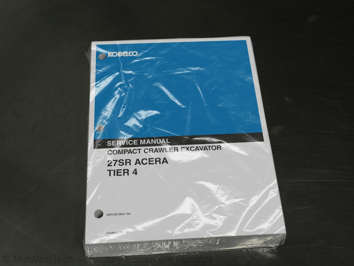
Kobelco 27SR Acera Tier 4 Hydraulic Excavator Service Manual
841 pages · Publication S5PV0018E01
Added to your cart. View cart
- Models
- 27SR Acera Tier 4
- Manual type
- Service Manual
- Pages
- 841
- Publication
- S5PV0018E01
- Condition
- Brand new
What's inside
From the manual's own table of contents: 6 sections, 278 entries. See sample pages (PDF, 613 KB)
27SR ACERA SERVICE MANUAL1 topic
- Section Table of Contents
SECTION 1 - SAFETY AND GENERAL INFORMATION48 topics
- GENERAL PRECAUTIONS FOR MAKING REPAIRS
- Preparation Before Disassembling
- Safety When Disassembling And Assembling
- Disassembling and Assembling Hydraulic Equipment
- Removing Hydraulic Equipment Assembly
- Disassembling Hydraulic Equipment
- Inspecting Parts
- Assembling Hydraulic Equipment
- Installing Hydraulic Equipment
- Electrical Equipment
- Hydraulic Parts
- Weld Repair
- Environmental Issues
- INTERNATIONAL UNIT SYSTEM
- Introduction
- SPECIFICATIONS
- Components Name
- Machine Dimensions
- 27SR Acera (Canopy)
- 27SR Acera (Cab)
- Specifications and Performance
- Speed and Gradeability
- Engine
- Hydraulic Components
- Side Digging and Dozer
- Weight
- Machine and Components Weight (Dry)
- Transportation
- Type of Crawler Shoes
- Type of Bucket
- Engine Specifications
- Engine Performance Curve
- ATTACHMENT DIMENSIONS
- Boom
- Boom Dimensional Drawings
- Boom Maintenance Standards
- Arm Dimensional Drawings
- Arm Maintenance Standards
- Bucket
- Bucket Dimensional Drawings
- Detail Dimensional Drawings of Lug Section
- Detail Dimensional Drawings of Boss Section
- Dozer
- Dozer Dimensional Drawings
- Dozer Maintenance Standards
- Swing
- Swing Bracket Dimensional Drawings
- Swing Portion Maintenance Standards
SECTION 2 - MAINTENANCE43 topics
- TIGHTENING TORQUES FOR CAPSCREWS AND NUTS
- SCREW SIZE
- Capscrew (Bolt)
- Capscrew (Socket Bolt)
- TIGHTENING TORQUE FOR HOSE AND FITTING
- Joint (O-ring Type)
- Hydraulic Hose (30° Flare Type)
- TIGHTENING TORQUES FOR NUTS AND SLEEVES
- Sleeve Type Tube Fittings
- PLUGS
- Plug For Hydraulic Pipe Joint
- Plug For Hydraulic Equipment
- SPECIAL SPANNER FOR TUBE
- SPECIAL TOOLS
- APPLICATION OF SCREW LOCKING COMPOUND AND SEALING COMPOUND
- COUNTERWEIGHT LIFTING JIG
- UPPER FRAME LIFTING JIG
- HOW TO USE MAINTENANCE STANDARDS AND PRECAUTIONS
- Performance Inspection Standard Table
- Standard Value Table
- Measuring Engine Speed
- Engine Speed Measurement
- Measuring Hydraulic Oil Pressure
- Standard for Hydraulic Oil Pressure Measurement
- Pressure Measurement and Adjustment
- Measuring Travel Performances
- Travel
- Travel Deviation
- Movement Drift Due to Gravity
- Drain Rate On Travel Motor
- Measuring Slew Performances
- Slew Time
- Overrun When Slewing Stops
- Slew Drift Due To Gravity
- Drain Rate of Travel Motor
- Measuring Attachment Operating Performances
- Cylinder Speed
- Gravity Drift of Cylinders
- Measuring Slew Bearing Performances
- Slew Bearing-Bucket Tip Play
- Slew Bearing Play
- Measuring Crawler Tension
- Crawler Tension
SECTION 3 - SYSTEMS73 topics
- HYDRAULIC SYSTEM
- Function and Features of Hydraulic Circuit
- Hydraulic Circuits and Component Models
- Hydraulic Circuit Diagram
- Hydraulic Circuit Operation
- Color Coding Standard For Hydraulic
- Neutral Circuit
- Travel Operating Circuit
- Slew Operating Circuit
- Slew (Left) Operating Circuit
- Bucket Operating Circuit
- Bucket Digging Operation Circuit
- Bucket Dumping Operating Circuit
- Boom Operating Circuit
- Boom UP Operating Circuit
- Boom DOWN Operating Circuit
- Arm Operating Circuit
- Arm In Operating Circuit
- Operating Circuit for Arm Out
- Swing Operating Circuit
- Swing (Left) Operating Circuit
- Dozer Operating Circuit
- Dozer Down Operating Circuit
- Travel / Dozer Combined Operating Circuit
- Travel (1st Speed Forwarding) /Dozer Down Operating Circuit
- Travel / Boom Combined Operating Circuit
- Travel (1st Speed Forward) / Boom Up Operating Circuit
- Nibbler and Breaker Operating Circuit
- Nibbler Close Operating Circuit
- Nibbler Open Operating Circuit
- Breaker Blow Operating Circuit
- Schematic Piping for Hydraulic System
- ELECTRICAL SYSTEM
- How To Read Circuit Diagram and Harness Connection
- Electric Circuit Diagram
- Harness Connection
- Electrical Equipment and Harness
- Electrical Equipment List
- Harness and Cable List
- Arrangement Drawing for Components and Harness
- Relay Unit Portion ; PM24E00046F2
- Fuel Tank Portion ; PM21P00006F1
- Travel Alarm Portion (OPT) ; PM53E00005F1
- Heater Portion (OPT) ; PM21M00017F1
- Detail Of Harness and Cable
- Proportional N&B Harness (No. H-2: PH14E01041P1)
- Canopy Working Light Harness (No. H-9 ; PW11E01026D4)
- Boom Work Light Extension Harness (No. H-10 ; PW14E01034D1)
- Connection Harness with Cab (No. H-11 ;PW14E01041P1) (OPT)
- Cab Working Light Harness (No. H-12 ; PW80E01003D1) (OPT)
- Alarm Extension Harness (No. H-14 ; PM13E01095P1) (OPT)
- Air Filter Restriction SW. Harness (No. H-16 ; PW11E01044D3)
- Hydraulic Pump
- Summary
- Construction and Function
- Inner Construction
- Pilot Valve (ATT)
- Construction
- Operation
- Pilot Valve (Travel)
- Control Valve
- General View and Hydraulic Ports No
- Hydraulic Circuit
- Explanation of Operation
- Slewing Motor
- General View
- Function and Operation
- Construction of Slewing Motor
- Travel Motor
- Function
- Swivel Joint
- Cylinder
- Specifications of Electrical Equipment
SECTION 4 - DISASSEMBLY AND ASSEMBLY53 topics
- ATTACHMENTS
- Preface
- Specification of Tightening Torque
- REMOVING AND INSTALLING
- Components
- Removal
- Installation
- Preparation for Removal
- Removal of Swing Bracket and Cylinder
- Installation of Swing Bracket and Cylinder
- DISASSEMBLING AND ASSEMBLING
- Tools
- General Precautions
- Disassembly
- Assembly
- Maintenance Standards
- Jig List
- Troubleshooting
- UPPER STRUCTURE
- Canopy
- Canopy Removal
- Cab Removal Preparation
- Cab Door Adjustment
- Guard (Cover)
- Floor Plate Assembly
- Floor Plate Removal Preparation
- Floor Plate Removal
- Assembling Floor Plate
- Battery
- Removal Preparation
- Counterweight
- Solenoid Valve
- John Deere Multi-Control Valve
- Fuel Tank
- Disassembly Preparation
- Hydraulic Oil Tank
- Air Cleaner
- Generator
- UNDERCARRIAGE
- Components of Travel System
- Crawler
- Removing Rubber Crawler
- Installing Rubber Crawler
- Removal and Installation Procedures (Steel: Opt)
- Slide Plate and Upper Roller (If Applicable)
- Removal and Installation Procedures
- Upper Roller
- Disassembly and Assembly
- Lower Roller
- Front Idler
- Idler Adjuster
- Sprocket
- Slewing Bearing
SECTION 5 - TROUBLESHOOTING54 topics
- TROUBLESHOOTING THE HYDRAULIC SYSTEM
- Confirm Actual Troubled Conditions at Site
- Trouble Diagnosis : Hydraulic
- Attachment
- Travel Operation
- Slewing Operation
- Pump
- TROUBLESHOOTING (ELECTRICAL SYSTEM)
- Trouble Diagnosis : Electric System
- General
- Attachment Operation
- Deceleration
- TROUBLESHOOTING (ENGINE)
- Trouble Diagnosis : Engine
- Starting Trouble
- E/G Rotation Trouble
- Output Drops Down
- Other Trouble
- General
- Engine Nomenclature
- Specifications
- Fuel Oil, Lubricating Oil and Cooling Water
- Fuel oil
- Lubricating oil
- Cooling water
- Engine External Views
- Structural Description
- Exhaust gas emission regulation
- The Emission Standard in USA
- Engine identification
- Guarantee Conditions for the EPA Emission Standard
- Inspection and Adjustment
- Periodic Maintenance Schedule
- Periodic Inspection and Maintenance Procedure
- Check before Daily Operation
- inspection after initial 50 hours operation
- Inspection every 50 hours
- Inspection every 250 hours or 3 months
- Inspection every 500 hours or 6 months
- Inspection every 1,000 hours or one year
- Inspection every 2000 hours or 2 years
- Adjusting the no-load maximum or minimum speed
- Sensor Inspection
- Oil pressure switch
- Thermo switch
- Water leak check in cooling water system
- Radiator cap inspection
- Thermostat Inspection
- Adjusting Operation
- Long storage
- TROUBLESHOOTING
- Preparation before troubleshooting
- Quick Reference Table for Troubleshooting
- Troubleshooting by measuring Compression Pressure
Inside this manual
Real pages from this service manual (841 pages). Open the sample pages (PDF, 612 KB)
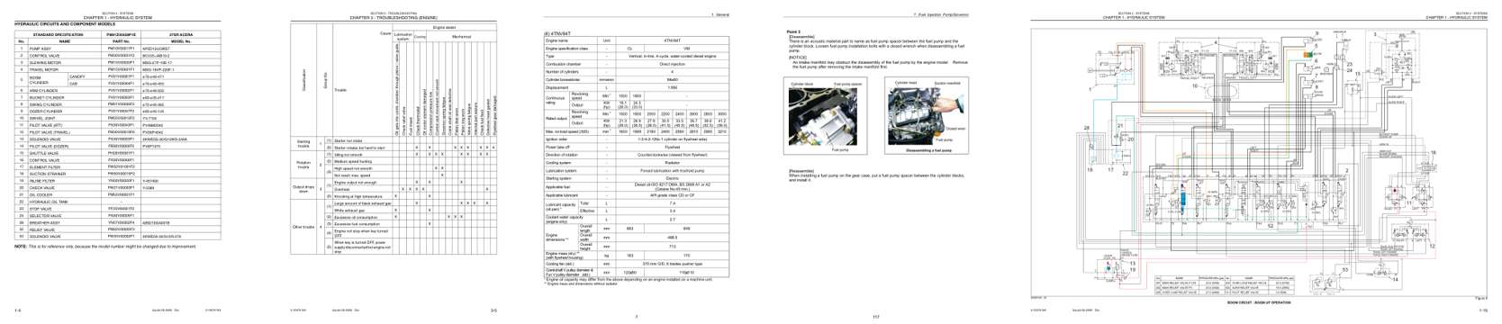
- Diagram, page 127: CHAPTER 1 - HYDRAULIC SYSTEM
- Troubleshooting, page 608: CHAPTER 3 - TROUBLESHOOTING (ENGINE)
- Specifications, page 647: 1. General
- Color page, page 757: 7. Fuel Injection Pump/Governor
- Foldout diagram (color), page 138: Issued 09-2008
This is a service manual
Here's how it compares to the other manual types.
Service manual
Factory repair procedures and technical information such as specifications, troubleshooting, and wiring and hydraulic diagrams, for the models and systems the manual covers. See What's inside for its topics.
Operator's manual
Safe operation, controls, maintenance schedules, lubrication points, inspections, and basic checks. Repair procedures are in the service manual.
Parts manual
Illustrated diagrams with factory part numbers for identifying components and ordering parts. Repair procedures are in the service manual.
Engine service manuals are sometimes sold separately, since certain machine models were offered with more than one engine option.
What it's used for
Factory manual for in-house farm and construction shop use. Straightforward, complete, and easy to follow. It contains the OEM information dealership service departments and parts counters use to diagnose problems, identify components, and perform maintenance or repairs correctly.
Service shops and owner/operators who repair their own equipment
Identifying correct parts and seeing how assemblies come apart and go back together
Keeping equipment running with less downtime
Factory manual, 841 pages
Quantity one is the manual described above.
Fast free USA shipping
Ships in 1 business day.
60-day returns
Free if the mistake is ours. A manual ordered in error must come back unopened in its shrink-wrap; you pay return shipping and a 20% restocking fee applies. Return policy
Binder not included
Manuals over about 300 pages may need a standard 3-ring binder, which you can buy locally to keep the pages organized for shop use.
Other editions and similar models
Questions about model, serial number, engine coverage or contents? Contact us before purchasing and we'll help confirm it's the right manual. Please verify the manual type, machine model, serial number range and engine coverage before purchasing: manuals ordered in error carry a 20% restocking fee (return policy).