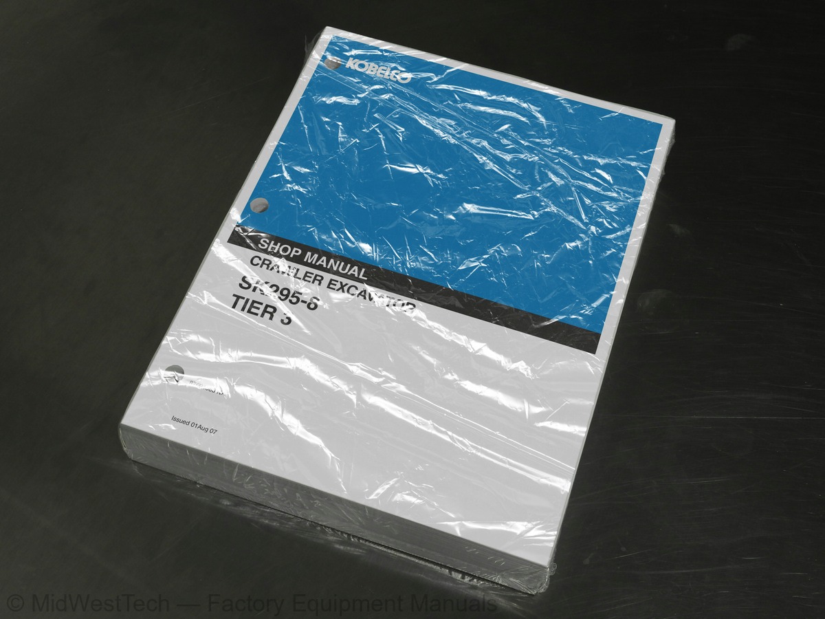
Kobelco SK295-8 Tier 3 Crawler Excavator Service Manual
838 pages · Publication 87694088
Added to your cart. View cart
- Models
- SK295-8 Tier 3
- Manual type
- Service Manual
- Pages
- 838
- Publication
- 87694088
- Condition
- Brand new
What's inside
From the manual's own table of contents: 9 sections, 481 entries. See sample pages (PDF, 751 KB)
SK295-8 SHOP MANUAL1 topic
- Section Table of Contents
SECTION 1 - SAFETY AND GENERAL INFORMATION140 topics
- SAFETY PRECAUTIONS
- Generalities
- Starting
- Operating
- Stopping
- MAINTENANCE
- Keep Hands and Clothes Far Off Moving Parts
- Do Not Smoke
- Do Not Look at The Welding Arc Without Proper Eye Protection
- Transfers and Transportation
- Engine
- Electrical System
- Hydraulic System
- Tools
- RECOGNIZE SAFETY INFORMATION
- Environmental Protection
- Follow Safety Precautions
- Prepare For Emergencies
- Wear Protective Clothing
- Protect Against Noise
- Inspect The Machine
- Use Hand Holds And Steps
- Adjust The Operator's Seat
- Fasten Seat Belt
- Move And Operate Machine Safely
- Operate Only From The Driver's Seat
- Do Not Carry Person On The Machine
- Confirm Direction Where The Machine Is To Be Driven
- Avoid Injury From Back Over And Swing Accidents
- Drive Machine Safely
- Avoid Overturning
- Park Machine Safely
- Investigate Job Site Before Operating The Machine
- Protecting Against The Fall Of Rocks And Landslides
- Dig With Caution
- Operate With Caution
- Avoid Electric Lines
- Keep Personnel Clear From Working Area
- Never Move The Bucket Over Any One
- Do Not Operate In Tunnels
- Never Undercut A High Bank
- Safety Loads Moving
- Avoid Excessive Digging Efforts
- Pay Attention When Digging Deeply
- Do Not Use The Traction Force Of The Machine For Digging
- Do Not Use The Turret Swing For Digging
- Do Not Use The Bucket As A Hammer
- Avoid Operating The Cylinders To Full Stroke
- Provide Signals For Jobs Involving A Number Of Machines
- Transporting The Machine Under Safe Conditions
- MAIN COMPONENTS
- Main Components – Upper Structure
- Main Components – Under Carriage
- Main Components – Front Attachment
- Hydraulic Components
- Hydraulic Pump
- Control Valve
- Pilot Valve
- Swing Motor Unit
- Travel Device
- Cylinders
- Excavator Performance
- Engine Data
- Digging Data
- Transporting Dimensions
- Bucket Applications as a Function of the Arms SK295-8
- PRECAUTIONS FOR DISASSEMBLY AND ASSEMBLY
- Preparations For Disassembly
- Disassembling and Assembling Hydraulic Equipment
- Disassembling Hydraulic Equipment
- Assembling Hydraulic Equipment
- Installing Hydraulic Equipment
- Bleeding Air From Hydraulic System
- Floating Seal Precautions
- Electrical Equipment
- TORQUE CHART
- Bolt Types
- Specified Tightening Torque Chart
- Bolt Tightening Order
- Service Recommendations for Split Flange
- Nut and Bolt Lockings
- Lock Plate
- Cotter Pin
- Lock Wire
- PIPING JOINTS
- Pipe Thread Connection / Union Joint Tightening Torque Specifications
- Union Joint
- O-ring Seal Joint
- Screwed-In Connection
- Seal Tape Application
- Low Pressure Hose Clamp Tightening Torque
- Connecting Hose
- HOW TO USE THE MAINTENANCE STANDARDS
- Standard and Cautions to be Exercised
- Application
- Terminology
- Cautions to be Exercised at Judgment
- Other Cautions to be Exercised
- Preparation For Performance Tests
- The Machine
- Test Area
- Precautions
- Make Precise Measurement
- PERFORMANCE INSPECTION STANDARD TABLE
- MEASUREMENT OF ENGINE SPEED
- Warming Up Of Engine
- Engine Speed Measured Value Through Service Diagnosis
- MEASUREMENT OF HYDRAULIC PRESSURE
- Preparing To Measure Hydraulic Pressure
- Place To Install Pressure Gauge
- Pressure Adjustment Position
- Pilot Relief Valve
- Swing Over Load Relief
- Procedure For Adjusting Relief Valve
- 2-Stage Main Relief Valve
- Over Load Relief Valve
- Over Load Relief Valve (Swing)
- Over Load Relief Valve (Travel)
- Measuring Travel Performances
- Travel Speed
- Deviation of Travel
- Performances of Parking Brake
- Drain Rate of Travel Motor
- Measuring Swing Performances
- Swing Speed
- Performance of Swing Brake
- Performance of Swing Parking Brake
- Drain Rate of Swing Motor
- Measuring Attachment Operating Performances
- Operating Time of Cylinders
- Oil Tightness of Cylinders
- Measuring Performances of Swing Bearing
- ENGINE CONTROL INPUT/OUTPUT
- Engine Control Equipment
- Speed Sensor
- Work Mode Select Switch
- Adjustment of Mechatro Controller Output
- Purpose of the Adjustment
- In Cases Where the Adjustment of Mechatro Controller Is Required
- Preparation
CHAPTER 5 - ATTACHMENT DIMENSIONS15 topics
- BOOM
- Boom Dimensional Drawings
- Boom Maintenance Standards
- Clearance of Pin and Bushing on Boom Section
- Clearance in Thrust Direction on the Boom Cylinder Installation Section
- Clearance In Thrust Direction on the Boom Foot Installation Section
- Arm Dimensional Drawing - Standard Arm 3.2 Meter (10 Ft 6 In)
- Arm Dimensional Drawing - Short Arm 4.0 Meter (13 Ft 1 In)
- Arm Maintenance Standards
- Clearance of Pin and Bushing on Arm Section
- Clearance in Thrust Direction on Arm and Arm Cylinder Installation Section
- Clearance in Thrust Direction on Idler and Bucket Links Installation Section
- BUCKET
- Bucket Installation
- Bucket Specifications
SECTION 2 - SYSTEMS38 topics
- PREFACE
- SUMMARY OF MECHATRO CONTROL SYSTEM
- Mechatro Control System In General
- Unload Valve Control
- Positive Control and P-q Control
- Boom Up Conflux Control
- Arm in Recirculation and Conflux Control
- Arm-in Anti-cavitation Control
- Arm-out Conflux Control
- Bucket Digging (Dump) Conflux Control
- Bucket Digging Anti-cavitation Control
- Swing Priority Control
- Travel Straight Control
- Pressure Release Control
- N&b Switch Control (Option)
- Option Conflux Control (Option)
- MECHATRO CONTROLLER
- Summary Of Multi Display
- Warning Table
- Self Diagnosis Display
- Service Diagnosis Display Function
- Trouble History Diagnosis
- Trouble Diagnosis Mode
- Set Procedure of Maintenance Schedule
- Adjusting Procedure of Display
- For Operator
- Function for Service
- Setting the Language
- Setting Adjusting Mode 1
- Adjusting Overload Pressure
- Drain Hydraulic Pressure
- Adjustment of Optional Hammer/Nibler
- Mechatro Control Equipment
- C-1 Mechatro Controller
- Gauge Cluster (Symbol C-2)
- Relay & Fuse Box (Symbol E-1)
- High Pressure Sensor : YN52S00048P1
- Low Pressure Sensor : YX52S00013P1
CHAPTER 1 - MECHATRO CONTROL SYSTEM125 topics
- COMMUNICATION OFF
- Washer motor relay
- SUMMARY
- HYDRAULIC CIRCUITS AND COMPONENTS
- Hydraulic Circuit Diagram
- N&B Hydraulic Circuit (Option)
- N&B Hydraulic Circuit Diagram
- Holding Valve For Boom and Arm (Option)
- Holding Valve For Boom And Arm Hydraulic Circuit Diagram
- Color Coding Standard For Hydraulic Circuits
- Neutral Circuit
- Operation of Bypass Cut Valve and Unloading Valve Housed in Control Valve
- Safety Lock Lever and Pilot Circuit
- Pump Positive Flow Control
- Pump P-q Curve Control Operation
- Neutral Circuit: Positive Control Function At Safety Lock Lever Down (Unlocked Position)
- Travel Circuit
- Travel Forward Pilot Simultaneous Operation Circuit
- 2-speed Travel Solenoid Command Circuit and Auto 1st Speed Return Function
- Travel Main Circuit
- Travel Motor Function
- Travel Circuit: Travel 2nd Speed, Rh & Lh Simultaneous Operation
- Bucket Circuit
- Pilot Circuit For Bucket Digging
- Auto Acceleration Operation
- Flow Control in the Work Mode
- Bucket Digging and Travel Priority Confluence (Conflux) Main Circuit
- Bucket Spool Stroke Limiter
- Control)
- Boom Circuit
- Boom Raise Pilot Circuit
- Boom Up 2 Pumps Conflux Main Circuit in C/V
- Boom Circuit: Boom Up Operation, Confluence Function
- Boom Down Pilot Circuit
- Prevention Of Natural Fall By Lock Valve And Actuation At Lowering
- Constant Recirculation Function of Boom Down Main Circuit
- Boom Circuit: Boom Down Operation and Prevention of Natural Boom Falling
- Swing Circuit
- Pilot Circuit for Left Swing
- Swing Auto Parking Brake
- Swing Main Circuit
- Swing Motor Circuit
- Swing Circuit: Swing Operation (LH)
- Arm Circuit
- Arm In, Light-load Operating Pilot Circuit
- Arm-in, Light-load Variable Normal Recirculation, Internal Conflux Main Circuit
- Arm Circuit: Arm In (Light Load) Operation, Arm Variable Recirculation and Cavitation Function
- Arm In, Heavy Load Operating Pilot Circuit
- Arm In, Heavy Load Operating Recirculation Cut Main Circuit
- Arm Circuit: Arm In (Heavy Load) Operation, Arm Confluence And Recirculation Cut Function
- Arm Out Pilot Circuit
- Arm Out 2 Pumps Conflux Main Circuit
- ELECTRICAL SYSTEM MAIN COMPONENTS
- Electrical System (Overall System)
- Cab Control
- Electrical Components
- Cluster Gauge
- Control Lever, Safety Lever
- Cluster Gauge Wiring Harness
- Mechatro Controller and Fuses & Relay Box
- Fuse & Relay box
- Fuses
- Relays
- Batteries, Batteries Relay, Fuses Link
- Hydraulic System Electrical Components (1/2)
- Hydraulic System Electrical Components (2/2)
- Engine Electrical Components
- Electrical Components (Lights, Horns)
- ELECTRICAL SYSTEM DIAGRAMS
- Electrical System Diagram Reading Key (No. 1)
- Electrical System Diagram (No. 1)
- Electrical System Diagram Reading Key (No. 2)
- Electrical System Diagram (No. 2)
- Electrical System Diagram Reading Key (No. 3)
- Electrical System Diagram (No. 3)
- Electrical System Diaram Reading Key (No. 4)
- Electrical System Diagram (No. 4)
- Electrical System Diagram Reading Key (No. 5)
- Electrical System Diagram (No. 5)
- WIRING HARNESS
- Cluster Guage Wiring Harness Assemby Reading Key
- Cluster Gauge Wiring Harness Assembly Diagram
- Platform Wirng Harness Assembly Reading Key
- Platform Wiring Harness Assembly Diagram
- Upper Frame Wiring Harness Assembly Reading Key
- Upper Frame Wiring Harness Assembly Diagram
- HYDRAULIC PUMP ASSEMBLY OUTLINE
- General View and Hydraulic Ports
- Specifications
- Main Pump
- Gear Pump (For Pilot)
- PTO Gear Case
- Operation
- Rotary Group
- Swash Plate Group
- Valve Block Group
- PTO Group
- REGULATOR
- Construction
- Adjusting the Regulator
- Causes Of Fault Resulting From Regulator
- Control Curve Of Pump
- PILOT VALVE (ATT) OUTLINE
- General View
- PILOT VALVE (TRAVEL) OUTLINE
- Outside View
- Performance Characteristics
- Construction and Operation
- CONTROL VALVE OUTLINE
- Control Valve Outside View (1/2)
- Control Valve Outside View (2/2)
- Control Valve Ports
- Control Valve (1/6)
- Control Valve (2/6)
- Control Valve (3/6)
- Control Valve (4/6)
- Control Valve (5/6)
- Control Valve (6/6)
- Main Relief Valve (601)
- Over Load Relief Valve (602, 603)
- Lock Valve Selector (211)
- Bypass Cut Valve (605)
- Swing Shuttle Valve Cover (204)
- Boost Check Valve (517)
- In Neutral Position
CHAPTER 5 - AIR CONDITIONING SYSTEM43 topics
- BASIC SYSTEM OF AIR CONDITIONER (HVAC AIR CONDITIONER)
- Air Cycle
- Auto Air Conditioner System Outline
- Component and Construction
- Component
- Receiver Dryer
- Function
- Mechanism of Cooling Circuit
- Characteristics of Refrigerant
- Component Parts
- Evaporator
- Expansion Valve
- Compressor
- Condenser
- Disassembly and Assembly
- Precautions to be Exercised in Operation
- Removing Inner Air Filter
- Removing Selector Box
- Removing Main Harness
- Removing Upper Unit Case
- Replacing Blower Controller
- Removing Heater Core
- Replacing Evaporator and Expansion Valve
- Replacing Motor Actuator
- CHARGING REFRIGERANT
- OPERATING PROCEDURE
- Procedure for the Generation of Vacuum
- Procedure for the Charging of the Gas
- ELECTRIC CIRCUIT
- Wiring Diagram and Connectors
- Connectors
- Structure and Operation of Each Functional Parts and the Inspection
- TROUBLESHOOTING
- Self Diagnosis Function On Display Of Panel
- Position of Indication for Failure
- Explanation of Indication for Failure
- Failure of Motor Actuator
- Failures of Sensors
- Communication Error of Control Amplifier and Panel
- Explanation of Monitor Mode
- Position of Monitor Mode Indication
- Operation of Monitor Mode
- Contents of Monitor Mode Display
SECTION 3 - DISASSEMBLY AND ASSEMBLY67 topics
- FRONT ATTACHMENT
- Removal
- Installation
- Maintenance to be Performed When Required
- Replacement Of Bucket
- Removing the Bucket
- Installing the Bucket
- Bucket Play Adjustment
- Bucket Teeth Replacement
- Cylinders Removal and Installation
- Bucket Cylinder Removal
- Bucket Cylinder Installation
- Arm Cylinder Removal
- Arm Cylinder Installation
- Boom Cylinders Removal
- Boom Cylinders Installation
- CYLINDER DISASSEMBLY AND ASSEMBLY
- Bucket Cylinder
- Bucket Cylinder Disassembly
- Bucket Cylinder Assembly
- Arm Cylinder
- Arm Cylinder Disassembly
- Arm Cylinder Assembly
- Boom Cylinders
- Boom Cylinders Disassembly
- Boom Cylinders Assembly
- Maintenance Standard: Rod
- UPPER STRUCTURE
- Removal of Upper Structure
- Removal and Installation of the Cab
- Removal and Installation of Counterweight
- Disconnecting Hoses of Swivel Joint Lower Side
- Removal and Installation of Main Frame
- Disassembly and Assembly of Hydraulic Pump Device
- Disassembly
- Assembly
- Maintenance Standard
- Repair Standards for Cylinder, Valve Plate and Swash Plate (Shoe Plate Face)
- PTO GEAR CASING
- Air Pulling Out Point
- Removal of Control Valve
- Installation of Control Valve
- Control Valve Ports (1/2)
- Control Valve Ports (2/2)
- Control Valve Diagrams
- Components
- Assembly and Disassembly of Control Valve
- Preparation For Disassembly
- Disassembling P1 Unload Spool
- Disassembling the Travel Spool (Left Travel and Right Travel)
- Disassembling the Boom Conflux Spool
- SWING BEARING
- Tool Table
- SWIVEL JOINT
- Inspection After Assembly
- TRACKS
- Link Pin and Track Bushing
- Master Pin
- Master Bushing
- Grouser Shoe
- TRACK ADJUSTER (WITH FRONT IDLER)
- DISASSEMBLY AND ASSEMBLY TRACK ADJUSTER
- FRONT IDLER ASSEMBLY
- Front Idler
- Axle and Bushing
- UPPER ROLLER
- LOWER ROLLER
SECTION 4 - TROUBLESHOOTING10 topics
- TROUBLESHOOTING OUTLINE
- Judgment Of Actual Thing At Site
- Get To The Site As Quickly As Possible
- Verify Background Of Trouble Occurred
- How To Diagnose Trouble
- Explanation Of The Cause Of Trouble
- Classification Of Failure And Troubleshooting
- The Blown Fuse of Mechatro Controller
- TROUBLESHOOTING BY ERROR CODE
- Error Codes
CHAPTER 2 - TROUBLESHOOTING BY TROUBLE33 topics
- TROUBLESHOOTING BY TROUBLE
- All Controls Do Not Function/Slow
- Engine Down/Stalled
- Move at Lever Neutral Position
- Poor Fine Operability
- Slow Boom Up, Insufficient Power
- Slow Boom Down, Insufficient Power For Lifting Up Body
- Slow Arm In, Insufficient Power
- Slow Independent Arm Out (In The Air)
- Slow Bucket Digging
- Slow Bucket Dump
- Swing Operation Not Functioned/Slow
- Noise During Swing Operation
- Swing on a Slope Drifts When Control Lever is in Neutral Position
- Swing Drifts When Swing Operation is Stopped
- Slow Travel Speed/Weak
- Travel Deviation
- Travel 1st/2nd Speed Not Changed
- Travel Parking on a Slope is Not Held
- Travel Does Not Run Straightly When Both Crawlers and Attachment Operated Simultaneously
- Slow Breaker (Crusher) Operation, Weak Power
- Option Selector Valve Malfunction: Not Switched To Breaker Circuit
- Option Selector Valve Malfunction: Not Switched To Nibbler Circuit
- Electric Systems
- Wiring Checking Procedure
- Trouble
- Engine Does Not Stop
- CPU Data Communication Error is Displayed on Multi Display
- Auto Accel Does Not Actuate
- Wiper Does Not Function
- How To Use and Flow Chart
- Table 1 - Failure Diagnosis Mode-1/ Diagnosis Item
- Table 2 - Failure Diagnosis Mode-1/ Diagnosis and Remedy
Inside this manual
Real pages from this service manual (838 pages). Open the sample pages (PDF, 750 KB)

- Specifications, page 132: CHAPTER 5 - ATTACHMENT DIMENSIONS
- Diagram, page 216: Issued 02-2008
- Troubleshooting, page 780: CHAPTER 1 - TROUBLESHOOTING BY ERROR CODES
- Color page, page 458: Issued 08-2007
- Color page, page 520: Issued 08-2007
- Foldout diagram (color), page 222: Issued 02-2008
This is a service manual
Here's how it compares to the other manual types.
Service manual
Factory repair procedures and technical information such as specifications, troubleshooting, and wiring and hydraulic diagrams, for the models and systems the manual covers. See What's inside for its topics.
Operator's manual
Safe operation, controls, maintenance schedules, lubrication points, inspections, and basic checks. Repair procedures are in the service manual.
Parts manual
Illustrated diagrams with factory part numbers for identifying components and ordering parts. Repair procedures are in the service manual.
Engine service manuals are sometimes sold separately, since certain machine models were offered with more than one engine option.
What it's used for
Factory manual for in-house farm and construction shop use. Straightforward, complete, and easy to follow. It contains the OEM information dealership service departments and parts counters use to diagnose problems, identify components, and perform maintenance or repairs correctly.
Service shops and owner/operators who repair their own equipment
Identifying correct parts and seeing how assemblies come apart and go back together
Keeping equipment running with less downtime
Factory manual, 838 pages
Quantity one is the manual described above.
Fast free USA shipping
Ships in 1 business day.
60-day returns
Free if the mistake is ours. A manual ordered in error must come back unopened in its shrink-wrap; you pay return shipping and a 20% restocking fee applies. Return policy
Binder not included
Manuals over about 300 pages may need a standard 3-ring binder, which you can buy locally to keep the pages organized for shop use.
Other editions and similar models
Questions about model, serial number, engine coverage or contents? Contact us before purchasing and we'll help confirm it's the right manual. Please verify the manual type, machine model, serial number range and engine coverage before purchasing: manuals ordered in error carry a 20% restocking fee (return policy).