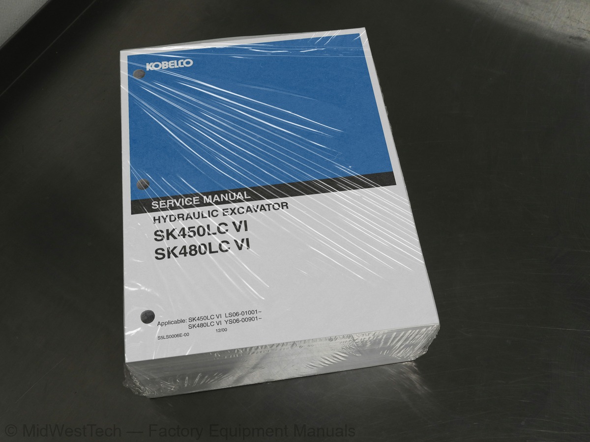
Kobelco SK450LC VI, SK480LC VI Hydraulic Excavator Service Manual
1,496 pages · Publication S5LS0006E
Added to your cart. View cart
- Models
- SK450LC VI, SK480LC VI
- Serial coverage
- SK450LC VI LS06-01001~, SK480LC VI YS06-00901~
- Manual type
- Service Manual
- Pages
- 1,496
- Publication
- S5LS0006E
- Condition
- Brand new
What's inside
From the manual's own table of contents: 16 sections, 386 entries. See sample pages (PDF, 655 KB)
Book code No94 topics
- NAME OF COMPONENTS
- GENERAL DIMENSIONS
- WEIGHT OF COMPONENTS
- TRANSPORTATION
- MACHINE LIFTING PROCEDURE
- WORKING RANGE
- LIFTING DIAGRAM
- SPECIFICATIONS AND PERFORMANCE
- TYPE OF CRAWLER
- TYPE OF BUCKET
- COMBINATIONS OF ATTACHMENT
- ENGINE SPECIFICATIONS
- BOOM
- Boom dimensional drawing
- Boom maintenance standard
- Arm dimensional drawing
- Arm maintenance standard
- BUCKET
- Bucket dimensional drawing
- Bucket dimensional table
- Dimensional drawing of lug section
- Dimensional drawing of boss section
- TIGHTENING TORQUES FOR CAPSCREWS AND NUTS
- SCREW SIZE AND TOOLS NOMINAL SIZE
- TIGHTENING TORQUES FOR NUTS AND SLEEVES
- PLUG
- SPECIAL SPANNER FOR TUBE
- SPECIAL TOOLS
- AND SEALING COMPOUND
- SUCTION STOPPER
- UPPER FRAME LIFTING JIG
- ENGINE MOUNTING PEDESTAL
- EXCAVATOR
- Attachment
- Cab & Guard
- Swing frame
- Travel system
- Electric equipment
- ENGINE STANDARD MAINTENANCE TIME TABLE
- AND CAUTIONS TO BE EXERCISED
- PERFORMANCE INSPECTION STANDARD TABLE
- MEASUREMENT OF ENGINE SPEED
- MEASUREMENT OF HYDRAULIC PRESSURE
- MEASURING TRAVEL PERFORMANCES
- MEASURING SWING PERFORMANCES
- MEASURING PERFORMANCES OF SWING BEARING
- MECHATRO CONTROLLER ADJUSTMENT
- SUMMARY OF MECHATRO CONTROL SYSTEM
- Mechatro Control System in General
- Pump Control
- Bucket Conflux Control
- Conflux Control for Boom Raise
- Recirculation Control at Light Load Arm In
- Arm In Recirculation Cut and Conflux Control
- Arm Out Conflux Control
- Travel Straight Control
- Swing Priority Control
- MECHATRO CONTROLLER
- Summary of Mechatro Controller
- Self Diagnosis Display Function
- Service Diagnosis
- Trouble History Diagnosis
- How to Correct the E/G Oil Supply Cumulative Time
- Mechatro Control Equipment
- SUMMARY
- HYDRAULIC CIRCUIT AND COMPONENTS
- NEUTRAL CIRCUIT
- TRAVEL CIRCUIT
- BUCKET CIRCUIT
- BOOM CIRCUIT
- SWING CIRCUIT
- ARM CIRCUIT
- COMBINED CIRCUIT
- PILOT PIPING
- MAIN PIPING
- ELECTRIC CIRCUIT DIAGRAM
- ELECTRIC EQUIPMENT
- HARNESS
- List of Harness
- Chart of Harness Connection
- Controller Assy
- Instrument Panel Assy
- Electric Assy
- Upper Harness Assy
- Engine Harness Assy
- Upper Harness Assy (Floor Plate)
- Cab Assy
- Cab Harness Assy
- Cab Light Install
- Battery, Battery Install
- Deck Light Install
- Boom Harness Assy, Boom Light Install
- Swing Flasher Light Install
- Fuel Pump Assy
SCHEMATICS36 topics
- HYDRAULIC CIRCUIT DIAGRAM
- Ⅰ. HYDRAULIC COMPONENTS
- Hydraulic Pump・Regulator
- Control Valve
- Pilot Valve (ATT)
- Pilot Valve (Travel)
- Swing Motor Unit
- Travel Motor
- Swivel Joint
- Hydraulic Cylinder
- Ⅱ. ELECTRIC EQUIPMENT
- List of Electric Equipments
- Specification of Electric Equipments
- CONSTRUCTION AND PIPING
- Construction
- Piping
- CONSTRUCTION OF MAIN COMPONENTS
- Intake Unit
- Air-Conditioner Unit
- Receiver Dryer
- FUNCTION
- Mechanism of Cooling Circuit
- Cooling Circuit
- Component Parts
- DISASSEMBLY AND ASSEMBLY
- Precautions to be Exercised in Operation
- Removal and Installation of Unit
- CHARGING REFRIGERANT
- Operating Procedure
- Charging Procedure
- ELECTRIC CIRCUIT
- Wiring Diagram and Connectors
- Inspecting Functional Parts
- TROUBLESHOOTING
- ATTACHMENT ASSY AND NAME
- CYLINDER
Dynamic Acera 10/01 Rev. 0159 topics
- Operator Seat
- Battery
- Guard
- Under Cover
- Fuel Tank
- Hydraulic Tank
- Hydraulic Pump
- Air Cleaner
- Muffler
- Counterweight
- Radiator &Oil Cooler
- Engine
- Instrument Panel
- Multi Control Valve (If equipped)
- Pilot Valve (for Att)
- Pilot Valve (for Travel)
- Upper Frame
- Pump
- TRAVEL SYSTEM
- Removing crawler
- Installing
- Construction
- Maintenance standard
- Tools and jigs
- Upper roller assy
- Removing
- Installing
- Construction
- Disassembly and Assembly
- Maintenance standard
- Tools and jigs
- Lower roller assy
- Removal
- Installation
- Construction
- Disassembly and Assembly
- Maintenance standard
- Tools and jigs
- Front idler assy
- Removing
- Idler assy
- Idler adjuster assy
- Removing
- Installing
- Maintenance standard
- Sprocket tooth profile gauge
- Travel motor
- Removing
- Installing
- Swing bearing assy
- Removing
- Installing
- Construction
- Disassembly and Assembly
- Maintenance Standard
- OUTLINE
- TROUBLESHOOTING ; MECHATRO CONTROL
- OUTLINE ; MECHATRO CONTROL
- CHECK POINTS FOR MECHATRO SYSTEM
GENERAL5 topics
- VIEW
- Major Specifications
- GENERAL BOLTS AND NUTS
- TABLE
- Application
ENGINE10 topics
- Camshaft
- Disassembly
- Service Standards Table
- Inspection
- lightening Torque Table
- Reassembly
- Crankcase and Main Moving Parts
- Measuring Compression Pressure
- Cylinder Head and Valve Mechanism
- Clearances
LUBRICATION8 topics
- Disassembly and inspection
- Reassembly
- Oil Filter and Oil Cooler
- 3.2 ]]ghtening Torque Table
- Oil filter
- Oil cooler
- Oil Pump
- Regulator Valve
FUEL AND ENGINE16 topics
- Pump Drive Case
- Disassembly and inspection
- Tightening Torque Table
- Injection Nozzle
- Cleaning and inspection
- Pump Assembly
- Reassembly and adjustment
- Bleeding of Fuel System
- <KBL2.1 injection nozzle>
- the Injection Pump
- <KBL2.4 injection nozzle>
- and adjustment of
- Fuel Filter
- fuel injection start timing
- Water Separator
- and maximum no-load speeds
ELECTRONICALLY20 topics
- Causes of Diagnostic Trouble Code Issue
- Principle of operation
- and Inspection Items
- Electronic Governor
- Diagnostic trouble codes
- Electronic ~mer
- Diagnostic trouble code issue
- 13mer Control Valve
- and check items
- Electronic Control System
- Multi-Use Tester II Service Data
- ECU Terminal Configuration
- Tester II
- Using ECU Connector
- Inspection Procedures
- Diagnostic function
- Inspection flowchart
- Checks on Transient Troubles
- Connection of Multi-Use Tester II
- Special tools
COOLING14 topics
- Fan Drive
- Disassembly and inspection
- Reassembly
- Tension Pulley
- Inspection of Auto Cool Fan
- Coupling
- Inspection of Radiator
- Water Pump
- V-belt Tension
- Adjustment
- Cleaning of Cooling System
- Thermostat
- Gas Leak Test
- Bleeding the Cooling System
INTAKE12 topics
- Disassembly and reassembly
- Inspection and cleaning
- Turbocharger
- 3.2 ]3ghtening Torque Table
- SPECIAL TOOL
- Aftercooler
- Disassembly and reassembly
- System
- Air pressure test
- of Exhaust
- Standard>
- Air Cleaner
ENGINE ELECTRICAL60 topics
- Starter
- Inspection and adjustment after
- Alternator
- installation
- Safety Relay
- A, 50 A Alternators
- Intake Air Heater
- (brushless type)
- Automatic Stop System
- Shutdown type
- Run-on type
- Service Standards Table
- Tightening Torque Table
- SPECIAL TOOL
- A Alternator
- Ressembly
- Safety Relay Inspection
- Inspection and adjustment
- Preheater
- after reassembly
- Starter Relay
- Heater relay
- Automatic Stop System
- (with brush type)
- Shut down type
- Run-on type
- HYDRAULIC BREAKER
- A. SELECTION OF THE HYDRAULIC BREAKER
- B. BEFORE OPERATING THE HYDRAULIC BREAKER
- C. HYDRAULIC OIL LEVEL CHECK AND CONTAMINATION PREVENTION
- D. BASIC OPERATION
- NIBBLER/BREAKER
- A. MACHINE SET-UP
- B. BASIC MACHINE OPERATION
- B (Breaker) Mode – See Figure 9.8 and 9.9
- Control Pedal
- a. Hydraulic breaker single circuit
- b. Nibbler and breaker combined (conflux) circuit
- SAFETY PRECAUTIONS
- A. USE FOR INTENDED PURPOSE– FIGURE 9.11
- B. PASSENGERS
- C. PROTECTIVE EQUIPMENT– FIGURE 9.12
- D. CYLINDERS– FIGUE 9.13
- E. AVOID CONTINUOUS OPERATION – FIGURE 9.14
- F. HOSE SURGE– FIGURE 9.15
- G. DO NOT USE DROPPING FORCE– FIGURE 9.16
- H. DO NOT USE SWING FORCE– FIGURE 9.17
- I. DO NOT LIFT– FIGURE 9.18
- J. WORKING RANGES– FIGURE 9.19
- GETTING THE MOST OUT OF YOUR BREAKER
- A. BREAKER PROPER POSITIONING
- B. APPLIED PRESSURE ON BREAKER
- C. BREAKING OVERSIZE ROCKS
- D. SURFACE ROCK DEMOLITION
- E. EXCAVATING AND TRENCHING
- F. RULES TO REMEMBER
- MAINTENANCE FOR NIBBLER/BREAKER
- PATTERN CONTROL CHANGE
- INSTALLATION OF VANDALISM GUARDS
- HYDRAULIC SCHEMATIC COUNTERWEIGHT REMOVAL
COMPILATION OF THIS2 topics
- AND UNITS
- UNITS
ENGIN2 topics
- Measuring Compression Pressure
- Oil Filter and Oil Cooler
FUEL AND ENGINE CONTROL25 topics
- Bleeding of Fuel System
- Injection Nozzle
- Fuel Filter
- Water Separator
- Electronic Timer
- Timer Control Valve
- conditions, and check items
- Actuator Tests Using Multi-Use
- Inspection Using ECU Connector
- Inspection instructions
- 5.2 .Water Pump
- Inspection of Radiator
- V-belt Tension
- Inspection
- Adjustment
- Cleaning of Cooling System
- lightening Torque Table
- TOOL
- Reassembly
- 5.7 150 A Alternator
- Safety Relay Inspection
- Preheater
- Intake air heater
- Heater relay
- 5,10 Automatic Stop System
CLUTCH3 topics
- 3.2 ~ghtening Torque Table
- Clutch Proper
- Bearing Case
SPECIAL4 topics
- Air Compressor
- Air Pressure Governor
- Air Compressor
- Air Pressure Governor
Inside this manual
Real pages from this service manual (1,496 pages). Open the sample pages (PDF, 655 KB)

- Diagram, page 200: Fig. 10 (2/2) Upper harness (EU)
- Troubleshooting, page 913: COOLING - TROUBLESHOOTING
- Specifications, page 1,235: FUEL AND ENGINE
- Color page, page 1,079: Applicable Engine Models: 6D24, 6D24-T, 6D25-TC, 6D24-TL
- Color page, page 628: Fig. 1-22 Removing Carrier 1 Assy
- Foldout diagram (color), page 172: C-1: MECHATRO CONTROLLER
This is a service manual
Here's how it compares to the other manual types.
Service manual
Factory repair procedures and technical information such as specifications, troubleshooting, and wiring and hydraulic diagrams, for the models and systems the manual covers. See What's inside for its topics.
Operator's manual
Safe operation, controls, maintenance schedules, lubrication points, inspections, and basic checks. Repair procedures are in the service manual.
Parts manual
Illustrated diagrams with factory part numbers for identifying components and ordering parts. Repair procedures are in the service manual.
Engine service manuals are sometimes sold separately, since certain machine models were offered with more than one engine option.
What it's used for
Factory manual for in-house farm and construction shop use. Straightforward, complete, and easy to follow. It contains the OEM information dealership service departments and parts counters use to diagnose problems, identify components, and perform maintenance or repairs correctly.
Service shops and owner/operators who repair their own equipment
Identifying correct parts and seeing how assemblies come apart and go back together
Keeping equipment running with less downtime
Factory manual, 1,496 pages
Quantity one is the manual described above.
Fast free USA shipping
Ships in 1 business day.
60-day returns
Free if the mistake is ours. A manual ordered in error must come back unopened in its shrink-wrap; you pay return shipping and a 20% restocking fee applies. Return policy
Binder not included
Manuals over about 300 pages may need a standard 3-ring binder, which you can buy locally to keep the pages organized for shop use.
Other editions and similar models
Questions about model, serial number, engine coverage or contents? Contact us before purchasing and we'll help confirm it's the right manual. Please verify the manual type, machine model, serial number range and engine coverage before purchasing: manuals ordered in error carry a 20% restocking fee (return policy).