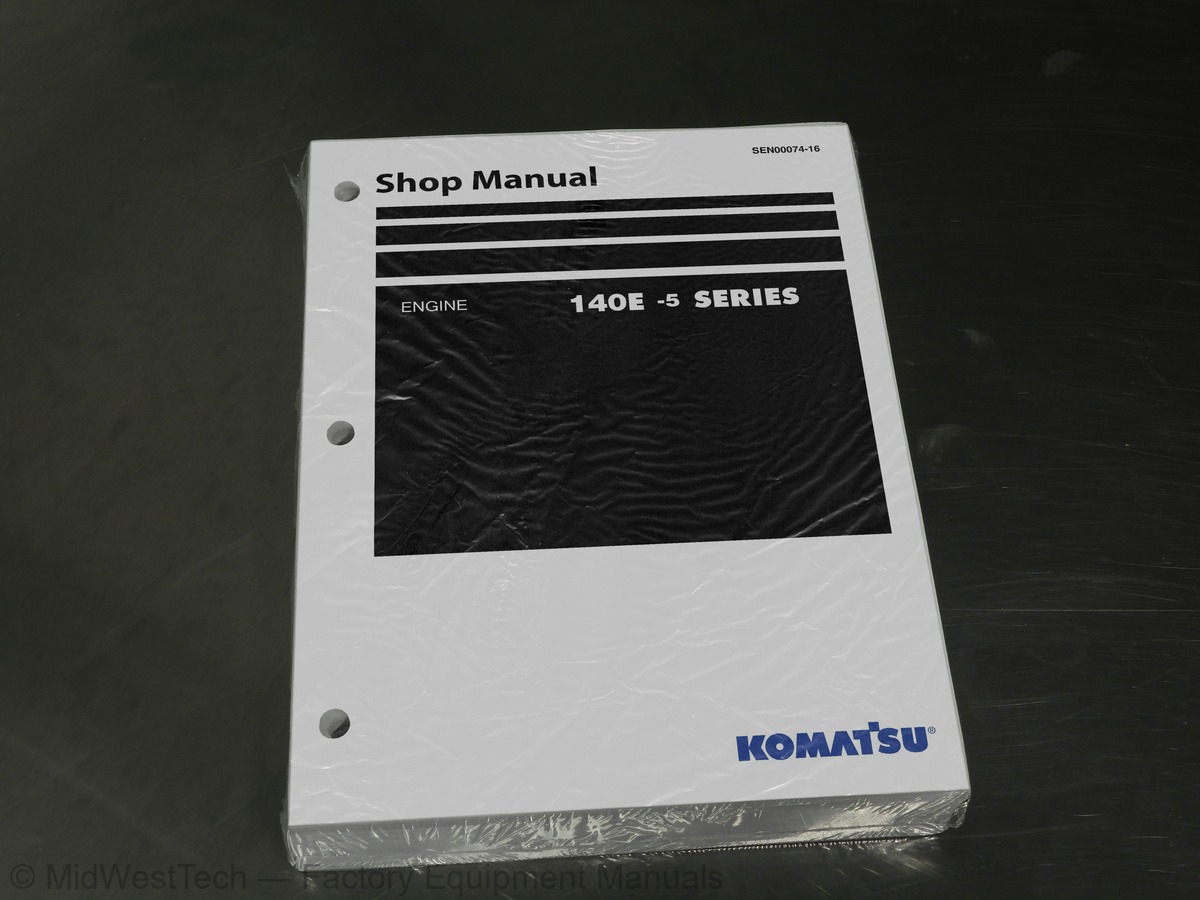
Komatsu 140E-5 Series Engine Service Manual
765 pages · Publication SEN00074-16
Added to your cart. View cart
- Models
- 140E-5 Series
- Manual type
- Service Manual
- Pages
- 765
- Publication
- SEN00074-16
- Condition
- Brand new
What's inside
From the manual's own table of contents: 8 sections, 245 entries. See sample pages (PDF, 537 KB)
Index and foreword36 topics
- Shop Manual, contents binder, binder label and tabs
- Index and foreword
- Foreword and general information
- Specification
- Specification and technical data
- Structure, function and maintenance standard
- Structure, function and maintenance standard, Part 1
- Structure, function and maintenance standard, Part 2
- Standard value table
- Standard service value table
- Testing and adjusting
- Troubleshooting
- General information on troubleshooting
- Troubleshooting of mechanical system (S-mode)
- Troubleshooting of electrical system (E-mode), Part 1
- Troubleshooting of electrical system (E-mode), Part 2
- Disassembly and assembly
- General information on disassembly and assembly
- Disassembly and assembly, Part 1 (with EGR)
- Disassembly and assembly, Part 2 (EGR-less)
- Disassembly and assembly, Part 3
- Repair and replacement of parts
- Information related to repair and replacement
- Cylinder head
- Cylinder block
- Composition of shop manual
- Safety notice
- How to read the shop manual
- Explanation of terms for maintenance standard
- Handling of electric equipment and hydraulic component
- Handling of connectors newly used for engines
- How to read electric wire code
- Precautions when carrying out operation
- Method of disassembling and connecting push-pull type coupler
- Standard tightening torque table
- Conversion table
Specification5 topics
- Outline
- Specifications
- General view
- Weight table
- Engine performance curves
Structure, function and maintenance standard48 topics
- Air intake and exhaust unit
- Air cleaner
- Turbocharger
- Aftercooler
- Muffler
- EGR system
- Cylinder liner
- Main moving parts
- Crankshaft
- Camshaft
- Cam follower and push rod
- Piston, piston ring and piston pin
- Connecting rod
- Flywheel and flywheel housing
- Vibration damper
- Timing gear
- Valve system
- Valve and valve guide
- Rocker arm and shaft
- Crosshead and guide
- Lubrication system
- Lubrication system diagram
- Oil pump
- EGR oil pump
- Oil filter
- Oil cooler
- Fuel system
- CRI system diagram
- Outline of CRI system
- Fuel piping
- Fuel cooler
- Fuel filter
- Priming pump
- Electric priming pump
- Engine controller cooler
- Cooling system
- Cooling system diagram
- Water pump
- Thermostat
- Corrosion resistor
- Cooling fan drive
- Accessories
- Front PTO
- Electrical equipment
- Alternator
- Starting motor
- Starting aid
- Engine controller
Standard value table2 topics
- Standard service value table for testing, adjusting, and troubleshooting
- Running-in standard and performance test standard
Testing and adjusting22 topics
- Testing and adjusting (with EGR)
- Testing and adjusting tools list
- Sketches of special tools
- Testing air boost pressure
- Testing exhaust temperature
- Adjusting valve clearance
- Testing compression pressure
- Testing blow-by pressure
- Testing engine oil pressure
- Testing EGR valve and bypass valve drive oil pressure
- Handling fuel system parts
- Releasing residual pressure in fuel system
- Testing fuel pressure
- Reduced cylinder mode operation
- No-injection cranking
- Testing fuel return rate and leakage
- Bleeding air from fuel circuit
- Testing fuel system for leakage
- Testing and adjusting alternator belt tension
- Testing and adjusting fan belt tension
- Handling controller high-voltage circuit
- Testing and adjusting (EGR-less)
Troubleshooting83 topics
- Points to remember when troubleshooting
- Method of displaying trouble diagnosis lamps (Method of displaying error code)
- Error codes and failure codes list
- Information in troubleshooting table
- Connection table for connector pin numbers
- T- branch box and T- branch adapter table
- Method of using troubleshooting charts
- S-1 Starting performance is poor
- S-2 Engine does not start
- S-3 Engine does not pick up smoothly
- S-4 Engine stops during operations
- S-5 Engine does not rotate smoothly
- S-6 Engine lacks output (or lacks power)
- S-7 Exhaust smoke is black (incomplete combustion)
- S-8 Oil consumption is excessive (or exhaust smoke is blue)
- S-9 Oil becomes contaminated quickly
- S-10 Fuel consumption is excessive
- S-11 Oil is in coolant (or coolant spurts back or coolant level goes down)
- S-12 Oil pressure drops
- S-13 Oil level rises (Entry of coolant/fuel)
- S-14 Coolant temperature becomes too high (overheating)
- S-15 Abnormal noise is made
- S-16 Vibration is excessive
- Troubleshooting method for disconnecting wiring harness of pressure sensor system
- E-1 Code [111/CA111] Engine Controller Internal Failure
- E-2 Code [115/CA115] Eng. Ne and Bkup Speed Sensor Error
- E-3 Code [122/CA122] Charge (boost) Air Press Sensor High Error
- E-4 Code [123/CA123] Charge (boost) Air Press Sensor Low Error
- E-5 Code [131/CA131] Throttle Sensor High Error
- E-6 Code [132/CA132] Throttle Sensor Low Error
- E-7 Code [135/CA135] Oil Press. Sensor High Error
- E-8 Code [141/CA141] Oil Press. Sensor Low Error
- E-9 Code [144/CA144] Coolant Temp. Sensor High Error
- E-10 Code [145/CA145] Coolant Temp. Sensor Low Error
- E-11 Code [153/CA153] Charge (boost) Air Temp. Sensor High Error
- E-12 Code [154/CA154] Charge (boost) Air Temp. Sensor Low Error
- E-14 Code [221/CA221] Ambient Air Press. Sensor High Error
- E-15 Code [222/CA222] Ambient Air Press. Sensor Low Error
- E-16 Code [227/CA227] Sensor Sup. 2 Volt. High Error
- E-18 Code [238/CA238] Ne Speed Sensor Sup. Volt. Error
- E-19 Code [263/CA263] Fuel Temp. Sensor High Error
- E-20 Code [265/CA265] Fuel Temp. Sensor Low Error
- E-25 Code [322/CA322] Injector #1 System Open/Short Error
- E-26 Code [323/CA323] Injector #5 System Open/Short Error
- E-27 Code [324/CA324] Injector #3 System Open/Short Error
- E-28 Code [325/CA325] Injector #6 System Open/Short Error
- E-29 Code [331/CA331] Injector #2 System Open/Short Error
- E-30 Code [332/CA332] Injector #4 System Open/Short Error
- E-31 Code [342/CA342] Engine Controller Data Matching Error
- E-32 Code [351/CA351] INJ. Drive Circuit Error
- E-34 Code [386/CA386] Sensor Sup. 1 Volt. High Error
- E-35 Code [431/CA431] Idle Validation Switch Error
- E-36 Code [432/CA432] Idle Validation Process Error
- E-37 Code [441/CA441] Supply Voltage Low Error
- E-38 Code [442/CA442] Supply Voltage High Error
- E-40 Code [451/CA451] Rail Press. Sensor High Error
- E-41 Code [452/CA452] Rail Press. Sensor Low Error
- E-43 Code [554/CA554] Rail Press Sensor In Range Error
- E-44 Code [559/CA559] No-pressure Feed By Supply pump 1
- E-45 Code [689/CA689] Eng. Ne Speed Sensor Error
- E-46 Code [731/CA731] Eng. Bkup Speed Sensor Phase Error
- E-47 Code [757/CA757] All Engine Controller Data Lost Error
- E-48 Code [778/CA778] Eng. Bkup Speed Sensor Error
- E-51 Code [1626/CA1626] Bypass Valve Solenoid Drive Short Circuit Error
- E-52 Code [1627/CA1627] Bypass Valve Solenoid Drive Open Error
- E-53 Code [1628/CA1628] Bypass Valve Servo Error 1
- E-54 Code [1629/CA1629] Bypass Valve Servo Error 2
- E-55 Code [1631/CA1631] Bypass Valve Lift Sensor High Error
- E-56 Code [1632/CA1632] Bypass Valve Lift Sensor Low Error
- E-58 Code [1642/CA1642] EGR Inlet Press Sensor Low Error
- E-59 Code [1653/CA1653] EGR Inlet Press Sensor High Error
- E-60 Code [2185/CA2185] Throttle Sens. Sup. Volt. High Error
- E-61 Code [2186/CA2186] Throttle Sens. Sup. Volt. Low Error
- E-62 Code [2249/CA2249] No-pressure Feed By Supply pump 2
- E-63 Code [2271/CA2271] EGR Valve Lift Sensor High Error
- E-64 Code [2272/CA2272] EGR Valve Lift Sensor Low Error
- E-65 Code [2351/CA2351] EGR Valve Solenoid Drive Short Error
- E-66 Code [2352/CA2352] EGR Valve Solenoid Drive Open Error
- E-67 Code [2555/CA2555] Intake Air Heater Relay Open Error
- E-68 Code [2556/CA2556] Intake Air Heater Relay Short Error
- E-69 Code [(143)/B@BAZG] Eng. Oil Press Low Torque Derate
- E-70 Code [(146)/B@BCNS] Eng. Overheat
- E-71 Code [(415)/B@BAZG] Eng. Oil Press. Low Speed Derate
Disassembly and assembly8 topics
- How to read this manual
- Coating materials list
- Special tools list
- General disassembly of engine
- General assembly of engine
- Removal and installation of fuel supply pump unit (with EGR)
- Removal and installation of fuel supply pump unit (EGR-less)
- Replacement of oil seal of engine mounted on machine
Repair and replacement of parts33 topics
- Flowchart
- Special tool table
- Special tool sketch
- Part names related to cylinder head
- Testing and inspection of cylinder head
- Pressure test of cylinder head
- Replacement of valve guide
- Replacement of valve seat insert
- Replacement of crosshead guide
- Repair of cylinder head mounting face by grinding
- Repair of valve by grinding
- Part names related to cylinder block
- Testing and inspection of cylinder block
- Method of checking main bearing metal inside diameter with alignment bar
- Part names related to crankshaft
- Testing and inspection of crankshaft
- Part names related to connecting rod
- Testing and inspection of connecting rod
- Replacement of flywheel ring gear
- Replacement of crankshaft gear
- Replacement of camshaft gear
- Replacement of main bearing metal cap
- Replacement of connecting rod small end bushing
- Replacement of cam bushing
- Repair of cylinder block top by grinding
- Repair of counterbore by grinding
- Check and identification after repair by grinding
- Gasket sealant application procedure
- Repair standard for cylinder liner O-ring
- Replacement of engine rear seal
- Replacement of wear sleeve (when sleeve is installed)
- Repair of crankshaft by grinding
- Improvement of surface roughness of crankshaft journal
Inside this manual
Real pages from this service manual (765 pages). Open the sample pages (PDF, 537 KB)
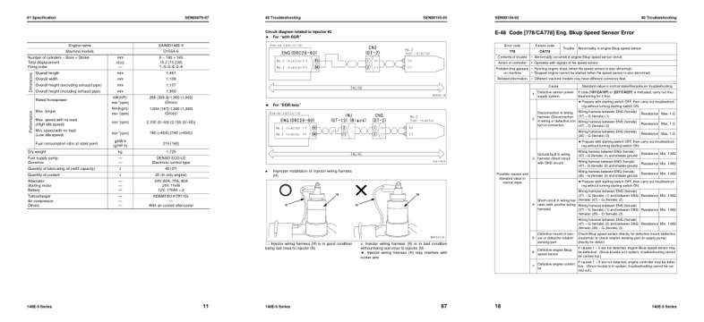
- Specifications, page 66: 01 Specification
- Diagram, page 506: Circuit diagram related to injector #2
- Troubleshooting, page 539: E-48 Code [778/CA778] Eng. Bkup Speed Sensor Error
This is a service manual
Here's how it compares to the other manual types.
Service manual
Factory repair procedures and technical information such as specifications, troubleshooting, and wiring and hydraulic diagrams, for the models and systems the manual covers. See What's inside for its topics.
Operator's manual
Safe operation, controls, maintenance schedules, lubrication points, inspections, and basic checks. Repair procedures are in the service manual.
Parts manual
Illustrated diagrams with factory part numbers for identifying components and ordering parts. Repair procedures are in the service manual.
Engine service manuals are sometimes sold separately, since certain machine models were offered with more than one engine option.
What it's used for
Factory manual for in-house farm and construction shop use. Straightforward, complete, and easy to follow. It contains the OEM information dealership service departments and parts counters use to diagnose problems, identify components, and perform maintenance or repairs correctly.
Service shops and owner/operators who repair their own equipment
Identifying correct parts and seeing how assemblies come apart and go back together
Keeping equipment running with less downtime
Factory manual, 765 pages
Quantity one is the manual described above.
Fast free USA shipping
Ships in 1 business day.
60-day returns
Free if the mistake is ours. A manual ordered in error must come back unopened in its shrink-wrap; you pay return shipping and a 20% restocking fee applies. Return policy
Binder not included
Manuals over about 300 pages may need a standard 3-ring binder, which you can buy locally to keep the pages organized for shop use.
Questions about model, serial number, engine coverage or contents? Contact us before purchasing and we'll help confirm it's the right manual. Please verify the manual type, machine model, serial number range and engine coverage before purchasing: manuals ordered in error carry a 20% restocking fee (return policy).