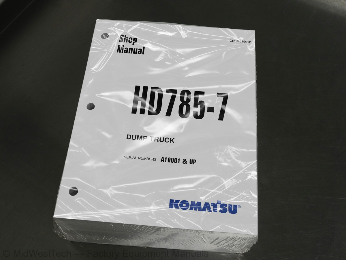
Komatsu HD7S5-7 Dump Truck Service Manual
1,818 pages · Publication CEBM019012
Added to your cart. View cart
- Models
- HD7S5-7
- Serial coverage
- A10001 & up
- Manual type
- Service Manual
- Pages
- 1,818
- Publication
- CEBM019012
- Condition
- Brand new
What's inside
From the manual's own table of contents: 279 sections, 566 entries. See sample pages (PDF, 758 KB)
Show all 279 sections
Accumulator charge valve40 topics
- Accumulator
- Slack adjuster
- Brake, parking brake
- Parking brake solenoid
- Retarder control valve
- Exhaust brake
- Suspension
- Suspension cylinder
- Rear axle support
- Steering and hoist hydraulic piping
- Steering, hoist filter (high pressure circuit)
- Dump body control
- Hydraulic tank
- Steering valve
- Crossover relief valve
- Steering cylinder
- Steering control valve
- Hoist valve
- Dump control valve (EPC valve)
- Hydraulic pump
- Auto greasing system
- Hoist cylinder
- ROPS cab
- Air conditioner
- Rear view monitor
- Controller related
- Machine monitor system
- Automatic shift control system
- Automatic emergency steering system
- Automatic suspension system
- Retarder control system
- Battery disconnector switch
- Dump control lever
- VHMS controller related
- ABS/ASR system
- Altitude setting function
- Sensors, switches
- Standard value table for engine
- Standard value table for machine
- Testing and adjusting tools list
Setting of payload meter built in VHMS51 topics
- Failure codes table
- Fuse locations
- Points to remember when troubleshooting
- Sequence of events in troubleshooting
- Check before troubleshooting
- Classification and procedures for troubleshooting
- Contents of troubleshooting table
- Connection table for connector pin numbers
- T-branch box and T-branch adapter table
- Failure code [1500L0] Dual engagement
- Failure code [15B0NX] Transmission oil filter: Clogging
- Failure code [15F0KM] R o F shifting abuse 1: Mistake in operation
- Failure code [15F0MB] R o F shifting abuse 2: Mistake in operation
- Failure code [15F7KM] Forward clutch disk abuse: Mistake in operation or setting
- Failure code [15G0MW] R clutch: Slipping
- Failure code [15G7KM] Reverse clutch disk abuse: Mistake in operation or setting
- Failure code [15H0MW] Hi clutch: Slipping
- Failure code [15J0MW] Lo clutch: Slipping
- Failure code [15K0MW] 1st clutch: Slipping
- Failure code [15L0MW] 2nd clutch: Slipping
- Failure code [15M0MW] 3rd clutch: Slipping
- Failure code [15N0MW] 4th clutch: Slipping
- Failure code [15SBL1] R clutch solenoid: Fill signal is ON when command current is OFF
- Failure code [15SBMA] R clutch solenoid: Malfunction
- Failure code [15SCL1] Hi clutch solenoid: Fill signal is ON when command current is OFF
- Failure code [15SCMA] Hi clutch solenoid: Malfunction
- Failure code [15SDL1] Lo clutch solenoid: Fill signal is ON when command current is OFF
- Failure code [15SDMA] Lo clutch solenoid: Malfunction
- Failure code [15SEL1] 1st clutch solenoid: Fill signal is ON when command current is OFF
- Failure code [15SEMA] 1st clutch solenoid: Malfunction
- Failure code [15SFL1] 2nd clutch solenoid: Fill signal is ON when command current is OFF
- Failure code [15SFMA] 2nd clutch solenoid: Malfunction
- Failure code [15SGL1] 3rd clutch solenoid: Fill signal is ON when command current is OFF
- Failure code [15SGMA] 3rd clutch solenoid: Malfunction
- Failure code [15SHL1] 4th clutch solenoid: Fill signal is ON when command current is OFF
- Failure code [15SHMA] 4th clutch solenoid: Malfunction
- Failure code [15SJMA] Lockup clutch solenoid: Malfunction
- Failure code [2F00KM] Parking brake: Mistake in operation or setting
- Failure code [2G42ZG] Accumulator: Oil pressure reduction (Front)
- Failure code [2G43ZG] Accumulator: Oil pressure reduction (Rear)
- Failure code [989A00] Engine over run prevention command signal: Operating
- Failure code [989D00] Rear section tipping over alarm: Alarm is activated
- Failure code [A570NX] Engine oil filter: Clogging
- Failure code [AA10NX] Air cleaner element: Clogging
- (R terminal signal is present and engine is stopped)
- Failure code [AB00MA] Alternator: Malfunction
- (Absence of R terminal signal and detection error)
- Failure code [B@BAZG] Abnormal lowering of engine oil pressure: Lowering of oil pressure
- Failure code [B@BAZK] Engine oil: Level too low
- Failure code [B@BCNS] Engine: Overheat
- Failure code [B@BCZK] Lowering of radiator coolant: Lowering of level
Failure code [CA234] Engine over speed (At left bank only): Excessively high speed19 topics
- Failure code [CA271] PCV1 short circuit (Left bank): Short circuit
- Failure code [CB271] PCV1 short circuit (Right bank): Short circuit
- Failure code [CA272] PCV1 disconnection (Left bank): Disconnection
- Failure code [CB272] PCV1 disconnection (Right bank): Disconnection
- Failure code [CA273] PCV2 short circuit (Left bank): Short circuit
- Failure code [CB273] PCV2 short circuit (Right bank): Short circuit
- Failure code [CA274] PCV2 disconnection (Left bank): Disconnection
- Failure code [CB274] PCV2 disconnection (Right bank): Disconnection
- Disconnection, short circuit
- Failure code [CA342] Engine controller data mismatch (Left bank): Mismatch
- Failure code [CB342] Engine controller data mismatch (Right bank): Mismatch
- Failure code [CA351] Abnormal injector drive circuit (Left bank): Abnormal circuit
- Failure code [CB351] Injector drive circuit abnormality (Right bank): Circuit abnormality
- Low voltage detection
- High voltage detection
- Failure code [CA431] Trouble in idle validation switch
- Failure code [CA432] Idle validation action error
- Abnormally high pressure occurrence
- Abnormally low voltage detection
Failure code [CA2556] Intake heater relay voltage high error (Left bank)38 topics
- Failure code [D180KA] Preheating relay output system: Disconnection
- Failure code [D180KB] Preheating relay output system: Grounding fault
- Failure code [D180KY] Preheating relay output system: Hot short circuit
- Failure code [D19HKB] Stop lamp relay output system: Short circuit
- Failure code [D1EFKA] Pre-lubrication start relay output system: Disconnection
- Failure code [D1EFKB] Pre-lubrication start relay output system: Grounding fault
- Failure code [D1EFKY] Pre-lubrication start relay output system: Hot short circuit
- Failure code [DAF9KM] Wrong connection of connector
- Failure code [DAFRKR] CAN communication error (Machine monitor): Communication error
- Lowering of source voltage
- Abnormality in controller
- Power source voltage too low
- Failure code [DAQ9KQ] Transmission controller: Disagreement of model selection
- Failure code [DAQRKR] Abnormality in CAN communication (Transmission)
- Failure code [DAQRMA] Transmission controller option setting: Malfunction
- Failure code [DB10KT] Retarder controller nonvolatile memory: Abnormality in controller
- Power source system trouble
- Failure code [DB19KQ] Disagreement of model selection (Retarder controller)
- Failure code [DB1RKR] CAN communication (retarder controller): Communication disabled
- Failure code [DB1RMA] Disagreement of option setting (Retarder controller)
- Failure code [DB2RKR] CAN communication (engine controller): Communication disabled
- VHMS controller: Low source voltage (input)
- (VHMS controller: Disagreement of model selection signals)
- VHMS controller battery power supply: Low source voltage (input)
- (VHMS controller 5 V power supply output: Low output voltage)
- (VHMS controller 24 V power supply output: Low output voltage)
- (VHMS controller 12 V power supply output: Low output voltage)
- CAN communication: Defective communication (Abnormality in target component system)
- Failure code [DBBRKR] Abnormality in CAN communication (VHMS)
- Failure code [DBC9KQ] Disagreement of model selection (ABS controller)
- Failure code [DBCRKR] Abnormality in CAN communication (ABS)
- Failure code [DBCRMA] Disagreement of option setting (ABS controller)
- Failure code [DBG2KK] Solenoid power supply: Low voltage
- Failure code [DBG3KK] Battery direct power supply: Low voltage
- Failure code [DBG9KQ] Model selection signal: Abnormal
- Out of input signal range
- Failure code [DDD8KA] ARSC system switch system: Disconnection
- Failure code [DDD8KB] ARSC system switch system: Short circuit
Suspension pressure sensor system: Disconnection or ground fault (Left front)44 topics
- Failure code [DHP6KA] Suspension pressure sensor system: Disconnection (Right rear)
- Out of input signal range (Right rear)
- Suspension pressure sensor system: Short circuit (Right rear)
- Suspension pressure sensor system: Disconnection or ground fault (Right rear)
- Failure code [DHP7KA] Suspension pressure sensor system: Disconnection (Left rear)
- Out of input signal range (Left rear)
- Suspension pressure sensor system: Short circuit (Left rear)
- Suspension pressure sensor system: Disconnection or ground fault (Left rear)
- Failure code [DHT5KX] Torque converter oil pressure sensor: Out of input signal range
- Disagreement of run and stop condition with signal
- Failure code [DHU2KX] Front accumulator oil pressure sensor: Out of input signal range
- Failure code [DHU3KX] Rear accumulator oil pressure sensor: Out of input signal range
- Failure code [DHU6KX] Trouble in ABS control valve pressure sensor (Front right)
- Failure code [DHU7KX] Trouble in ABS control valve pressure sensor (Front left)
- Failure code [DHU8KX] Trouble in ABS control valve pressure sensor (Rear right)
- Failure code [DHU9KX] Trouble in ABS control valve pressure sensor (Rear left)
- Failure code [DJF1KA] Fuel level sensor: Disconnection
- Failure code [DK30KX] Steering angle potentiometer: Trouble (Disconnection)
- Failure code [DK51L5] Trouble in retarder lever potentiometer and RVS
- Failure code [DK52KX] Failure in hoist lever potentiometer 1: Out of input signal range
- Failure code [DK53L8] Failure in hoist lever potentiometer 2: Disagreement of analog signal
- Failure code [DK54KX] Body positioner sensor: Out of input signal range
- Failure code [DKD0L6] Failure in steering angle speed sensor
- Failure code [DKH0KX] Pitch angle sensor: Out of input signal range
- Abnormality
- Failure code [DLF1KA] Transmission input shaft speed sensor: Disconnection
- Disagreement of revolution speed signal
- Failure code [DLF2KA] Transmission intermediate shaft speed sensor: Disconnection
- Failure code [DLF6KA] Disconnection in wheel speed sensor (Front right)
- Failure code [DLF6L3] Trouble in wheel speed sensor (Front right)
- Failure code [DLF7KA] Disconnection in wheel speed sensor (Front left)
- Failure code [DLF7L3] Trouble in wheel speed sensor (Front left)
- Failure code [DLF8KA] Wheel speed sensor: Disconnection (Rear right)
- Failure code [DLF8L3] Wheel speed sensor: Disconnection (Rear right)
- Failure code [DLF8LC] Wheel speed sensor: Trouble (Rear right)
- Failure code [DLF8MA] Wheel speed sensor: Disconnection (Rear right)
- Failure code [DLF9KA] Wheel speed sensor: Disconnection (Rear left)
- Failure code [DLF9L3] Wheel speed sensor: Trouble (Rear left)
- Failure code [DLF9LC] Wheel speed sensor: Trouble (Rear left)
- Failure code [DLF9MA] Wheel speed sensor: Disconnection (Rear left)
- Failure code [DLT3KA] Transmission output shaft speed sensor: Disconnection
- Failure code [DLT4KA] Transmission output shaft speed sensor: Disconnection
- Failure code [DLT4MA] Transmission output shaft speed sensor: Disconnection
- Failure code [DUM7KY] Pre-lubrication operation lamp output abnormality: Hot short circuit
Malfunction39 topics
- Failure code [DX13KA] Output circuit of hoist EPC valve: Disconnection
- Failure code [DX13KB] Output circuit of hoist EPC valve: Short circuit
- Failure code [DX13KY] Output circuit of hoist EPC valve: Short circuit with power source line
- Trouble (Valve keeps operating)
- Disconnection
- Ground fault
- Short circuit
- Trouble (Valve does not operate)
- Failure code [DX21KA] Disconnection in ABS control valve output circuit (Front right)
- Failure code [DX21KB] Ground fault in ABS control valve output circuit (Front right)
- Failure code [DX21KY] Hot short in ABS control valve output circuit (Front right)
- Failure code [DX21MA] Defective ABS control valve (Front right)
- Failure code [DX22KA] Disconnection in ABS control valve output circuit (Front left)
- Failure code [DX22KB] Ground fault in ABS control valve output circuit (Front left)
- Failure code [DX22KY] Hot short in ABS control valve output circuit (Front left)
- Failure code [DX22MA] Defective ABS control valve (Front left)
- Failure code [DX23KA] Disconnection in ABS control valve output circuit (Rear right)
- Failure code [DX23KB] Ground fault in ABS control valve output circuit (Rear right)
- Failure code [DX23KY] Hot short in ABS control valve output circuit (Rear right)
- Failure code [DX23MA] Defective ABS control valve (Rear right)
- Failure code [DX24KA] Disconnection in ABS control valve output circuit (Rear left)
- Failure code [DX24KB] Ground fault in ABS control valve output circuit (Rear left)
- Failure code [DX24KY] Hot short in ABS control valve output circuit (Rear left)
- Failure code [DX24MA] Defective ABS control valve (Rear left)
- Failure code [DX25MA] Defective ABS front wheel system control valve
- Failure code [DX26MA] Defective ABS rear wheel system control valve
- Failure code [DXH1KA] Lockup clutch solenoid output circuit: Disconnection
- Failure code [DXH1KB] Lock-up clutch solenoid output circuit: Short circuit
- Short circuit to power source line
- Failure code [DXH2KA] Hi clutch solenoid output circuit: Disconnection
- Failure code [DXH2KB] Hi clutch solenoid output circuit: Short circuit
- Failure code [DXH2KY] Hi clutch solenoid output circuit: Short circuit to power source line
- Failure code [DXH3KA] Lo clutch solenoid output circuit: Disconnection
- Failure code [DXH3KB] Lo clutch solenoid output circuit: Short circuit
- Failure code [DXH3KY] Lo clutch solenoid output circuit: Short circuit in power source line
- Failure code [DXH4KA] 1st clutch solenoid output circuit: Disconnection
- Failure code [DXH4KB] 1st clutch solenoid output circuit: Short circuit
- Failure code [DXH4KY] 1st clutch solenoid output circuit: Short circuit to power source line
- Failure code [DXH5KA] 2nd clutch solenoid output circuit: Disconnection
Excessive shock when starting or shifting excessive50 topics
- Transmission does not shift up
- Machine lacks power or speed when traveling
- Time lag is excessive when starting or shifting gear
- Torque converter oil temperature is high
- Torque converter oil pressure is low
- Front brake is ineffective
- Rear brake is ineffective
- Steering wheel is heavy
- Steering wheel does not work
- Steering wheel vibrates
- Dump body lifting speed is slow
- Dump body does not work
- Excessive hydraulic drift of dump body
- Method of using troubleshooting charts
- Starting performance is poor
- Engine does not start
- Engine does not pick up smoothly
- Engine stops during operations
- Engine does not rotate smoothly
- Engine lacks output (or lacks power)
- Exhaust smoke is black (incomplete combustion)
- Oil consumption is excessive (or exhaust smoke is blue)
- Oil becomes contaminated quickly
- Fuel consumption is excessive
- Oil is in coolant (or coolant spurts back or coolant level goes down)
- Oil pressure drops
- Oil level rises (Entry of coolant or fuel)
- Coolant temperature becomes too high (overheating)
- Abnormal noise is made
- Vibration is excessive
- How to read this manual
- Coating materials list
- Special tool list
- Sketches of special tools
- Removal and installation of fuel supply pump assembly
- Removal and installation of fuel injector assembly
- Removal and installation of cylinder head assembly
- Removal and installation of engine hood assembly
- Removal and installation of radiator assembly
- Removal and installation of engine assembly
- Removal and installation of engine front oil seal
- Removal and installation of engine rear oil seal
- Removal and installation of front drive shaft
- Removal and installation of rear drive shaft
- Removal and installation of output shaft assembly
- Disassembly and assembly of damper assembly
- Removal and installation of torque converter and transmission assembly
- Disconnection and connection of torque converter assembly and transmission assembly
- Disassembly and assembly of torque converter PTO assembly
- Disassembly and assembly of transmission assembly
Electrical circuit diagram for VHMS (If equipped)6 topics
- Electrical circuit diagram for ABS (Outside cab) (If equipped)
- Electrical circuit diagram for ABS (Inside cab) (If equipped)
- Electrical circuit diagram for ASR (If equipped)
- Air conditioner electrical circuit diagram (If equipped)
- Electrical circuit diagram for auto greasing (If equipped)
- Connectors table and arrangement drawing
Inside this manual
Real pages from this service manual (1,818 pages). Open the sample pages (PDF, 757 KB)

- Specifications, page 411: 10 Structure, function and maintenance standard
- Troubleshooting, page 1,223: Failure code [DLF9KA] Wheel speed sensor: Disconnection (Rear left) 1
- Diagram, page 1,335: Failure code [DX18KB] ASR proportional pressure reducing solenoid
- Foldout diagram, page 1,806: Electrical circuit diagram for inside cab (2/3)
This is a service manual
Here's how it compares to the other manual types.
Service manual
Factory repair procedures and technical information such as specifications, troubleshooting, and wiring and hydraulic diagrams, for the models and systems the manual covers. See What's inside for its topics.
Operator's manual
Safe operation, controls, maintenance schedules, lubrication points, inspections, and basic checks. Repair procedures are in the service manual.
Parts manual
Illustrated diagrams with factory part numbers for identifying components and ordering parts. Repair procedures are in the service manual.
Engine service manuals are sometimes sold separately, since certain machine models were offered with more than one engine option.
What it's used for
Factory manual for in-house farm and construction shop use. Straightforward, complete, and easy to follow. It contains the OEM information dealership service departments and parts counters use to diagnose problems, identify components, and perform maintenance or repairs correctly.
Service shops and owner/operators who repair their own equipment
Identifying correct parts and seeing how assemblies come apart and go back together
Keeping equipment running with less downtime
Factory manual, 1,818 pages
Quantity one is the manual described above.
Fast free USA shipping
Ships in 1 business day.
60-day returns
Free if the mistake is ours. A manual ordered in error must come back unopened in its shrink-wrap; you pay return shipping and a 20% restocking fee applies. Return policy
Binder not included
Manuals over about 300 pages may need a standard 3-ring binder, which you can buy locally to keep the pages organized for shop use.
Questions about model, serial number, engine coverage or contents? Contact us before purchasing and we'll help confirm it's the right manual. Please verify the manual type, machine model, serial number range and engine coverage before purchasing: manuals ordered in error carry a 20% restocking fee (return policy).