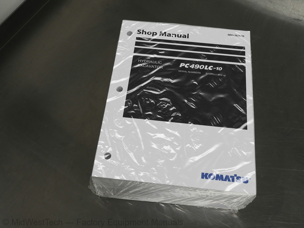
Komatsu PC490LC-10 Hydraulic Excavator Service Manual
1,682 pages · Publication SEN05622-05
Added to your cart. View cart
- Models
- PC490LC-10
- Serial coverage
- 80001 and up
- Manual type
- Service Manual
- Pages
- 1,682
- Publication
- SEN05622-05
- Condition
- Brand new
What's inside
From the manual's own table of contents: 316 sections, 611 entries. See sample pages (PDF, 889 KB)
Show all 316 sections
Solenoid valve3 topics
- Attachment circuit selector valve
- Center swivel joint
- Accumulator
Work equipment2 topics
- Work equipment shims
- Bucket play adjustment shim
Cab and its attachments2 topics
- Cab mount and cab tipping stopper
- ROPS cab
Electrical system4 topics
- Electrical control system
- Machine monitor system
- KOMTRAX system
- Sensor
Standard service value table2 topics
- Standard value table for engine
- Standard value table for machine
Related information on testing and adjusting32 topics
- Tools for testing and adjusting
- Sketch of tools for testing and adjusting
- Testing engine speed
- Testing boost pressure
- Testing exhaust gas color
- Testing and adjusting valve clearance
- Testing compression pressure
- Testing blowby pressure
- Testing engine oil pressure
- Testing EGR valve and KVGToil pressure
- Testing fuel pressure
- Testing fuel leakage and return
- Bleeding air from fuel system
- Testing fuel circuit for leakage
- Handling cylinder cutout mode operation
- Handling no-injection cranking operation
- Testing and adjusting air conditioner compressor belt tension
- Replacing alternator belt
- Fuel doser cleaning procedure
- Writing compensation values at replacement of injector and engine controller
- Testing swing circle bearing clearance
- Testing and adjusting track tension
- Releasing remaining pressure from hydraulic circuit
- Testing and adjusting oil pressure in work equipment, swing and travel circuits
- Testing oil pressure in control circuit
- Testing and adjusting oil pressure in pump PC control circuit
- Testing and adjusting oil pressure in pump LS control circuit
- Testing output pressure of solenoid valve
- Testing PPC valve output pressure
- Adjusting play of work equipment and swing PPC valves
- Testing pump swash plate sensor
- Testing fan speed
Precautions for KDPF (KCSF and KDOC) Cleaning and Replacement1 topic
- sensors)
Failure code [B@BCNS] Eng Water Overheat59 topics
- Failure code [B@BCZK] Eng Water Level Low
- Failure code [B@HANS] Hyd Oil Overheat
- Failure code [CA115] Eng Ne and Bkup Speed Sens Error
- Failure code [CA122] Chg Air Press Sensor High Error
- Failure code [CA123] Chg Air Press Sensor Low Error
- Failure code [CA131] Throttle Sensor High Error
- Failure code [CA132] Throttle Sensor Low Error
- Failure code [CA135] Eng Oil Press Sensor High Error
- Failure code [CA141] Eng Oil Press Sensor Low Error
- Failure code [CA144] Coolant Temp Sens High Error
- Failure code [CA145] Coolant Temp Sens Low Error
- Failure code [CA153] Chg Air Temp Sensor High Error
- Failure code [CA154] Chg Air Temp Sensor Low Error
- Failure code [CA187] Sensor 2 Supply Volt Low Error
- Failure code [CA221] Ambient Press Sensor High Error
- Failure code [CA222] Ambient Press Sensor Low Error
- Failure code [CA227] Sensor 2 Supply Volt High Error
- Failure code [CA234] Eng Overspeed
- Failure code [CA238] Ne Speed Sensor Supply Volt Error
- Failure code [CA239] Ne Speed Sens Supply Volt High Error
- Failure code [CA271] IMV/PCV1 Short Error
- Failure code [CA272] IMV/PCV1 Open Error
- Failure code [CA273] PCV2 Short Error
- Failure code [CA274] PCV2 Open Error
- Failure code [CA322] Inj #1(L#1) Open/Short Error
- Failure code [CA323] Inj #5(L#5) Open/Short Error
- Failure code [CA324] Inj #3(L#3) Open/Short Error
- Failure code [CA325] Inj #6(L#6) Open/Short Error
- Failure code [CA331] Inj #2(L#2) Open/Short Error
- Failure code [CA332] Inj #4(L#4) Open/Short Error
- Failure code [CA343] ECM Critical Internal Failure
- Failure code [CA351] Injectors Drive Circuit Error
- Failure code [CA352] Sensor 1 Supply Volt Low Error
- Failure code [CA356] Mass Air Flow Sensor High Error
- Failure code [CA357] Mass Air Flow Sensor Low Error
- Failure code [CA386] Sensor 1 Supply Volt High Error
- Failure code [CA441] Battery Voltage Low Error
- Failure code [CA442] Battery Voltage High Error
- Failure code [CA449] Rail Press Very High Error
- Failure code [CA451] Rail Press Sensor High Error
- Failure code [CA452] Rail Press Sensor Low Error
- Failure code [CA515] Rail Press Sens Sup Volt High Error
- Failure code [CA516] Rail Press Sens Sup Volt Low Error
- Failure code [CA553] Rail Press High Error
- Failure code [CA555] Crankcase Press High Error 1
- Failure code [CA556] Crankcase Press High Error 2
- Failure code [CA559] Rail Press Low Error
- Failure code [CA595] Turbo Speed High Error 2
- Failure code [CA687] Turbo Speed Low Error
- Failure code [CA689] Eng Ne Speed Sensor Error
- Failure code [CA691] Intake Temperature Sensor High Error
- Failure code [CA692] Intake Temperature Sensor Low Error
- Failure code [CA697] ECM Internal Temp Sensor High Error
- Failure code [CA698] ECM Int Temp Sensor Low Error
- Failure code [CA731] Eng Bkup Speed Sens Phase Error
- Failure code [CA778] Eng Bkup Speed Sensor Error
- Failure code [CA1117] Persistent Data Lost Error
- Failure code [CA1664] KDOC Malfunction
- Failure code [CA1691] Regeneration Ineffective
Failure code [CA3317] KDOC Outlet Temperature Sensor High Error59 topics
- Failure code [CA3318] KDOC Outlet Temp Sensor In Range Error
- Failure code [CA3319] KDPF Outlet Temperature Sensor High Error
- Failure code [CA3321] KDPF Outlet Temperature Sensor Low Error
- Failure code [CA3322] KDPF Outlet Temp Sensor In Range Error
- Failure code [CA3419] Mass Air Flow Sensor Power Supply High Error
- Failure code [CA3421] Mass Air Flow Sensor Power Supply Low Error
- Failure code [D110KB] Battery Relay Drive S/C
- Failure code [D19JKZ] Personal Code Relay Abnormality
- Failure code [D811MC] KOMTRAX Error
- Failure code [D862KA] GPS Antenna Open Circuit
- Failure code [D8ALKA] Operating Lamp Open Circuit (KOMTRAX)
- Failure code [D8ALKB] Operating Lamp Short Circuit (KOMTRAX)
- Failure code [D8AQKR] CAN2 Discon (KOMTRAX)
- Failure code [DA20MC] Pump Controller Malfunction
- Failure code [DA22KK] Pump Solenoid Power Low Error
- Failure code [DA25KP] 5V Sensor1 Power Abnormality
- Failure code [DA29KQ] Model Selection Abnormality
- Failure code [DA2LKA] Operating Lamp Open Circuit (Pump Con)
- Failure code [DA2LKB] Operating Lamp Short Circuit (Pump Con)
- Failure code [DA2QKR] CAN2 Discon (Pump Con)
- Failure code [DA2RKR] CAN1 Discon ( Pump Con)
- Failure code [DAF0MB] Monitor ROM Abnormality
- Failure code [DAF0MC] Monitor Error
- Failure code [DAF8KB] Camera Power Supply Short Circuit
- Failure code [DAF9KQ] Model Selection Abnormality
- Failure code [DAFGMC] GPS Module Error
- Failure code [DAFLKA] Operating Lamp Open Circuit (Monitor)
- Failure code [DAFLKB] Operating Lamp Short Circuit (Monitor)
- Failure code [DAFQKR] CAN2 Discon (Monitor)
- Failure code [DAZ9KQ] AC Model Selection Abnormality
- Failure code [DAZQKR] CAN2 Discon (AC)
- Failure code [DB2QKR] CAN2 Discon (Engine Con)
- Failure code [DB2RKR] CAN1 Discon (Engine Con)
- Failure code [DGH2KA] Hyd Oil Temp Sensor Open
- Failure code [DGH2KB] Hyd Oil Sensor Short Circuit
- Failure code [DHA4KA] Air Cleaner Clogging Sensor Open Circuit
- Failure code [DHPAMA] Pump Press Sensor Abnormality
- Failure code [DHPBMA] R Pump Press Sensor Abnormality
- Failure code [DHS3MA] Arm IN PPC Sen. Abnormality
- Failure code [DHS4MA] Bucket CURL PPC Press Sensor Abnormality
- Failure code [DHS8MA] Boom RAISE PPC Press Sensor Abnormality
- Failure code [DHS9MA] Boom LOWER Press Sensor Abnormality
- Failure code [DHSAMA] Swing RH PPC Press Sensor Abnomality
- Failure code [DHSBMA] Swing LH PPC Press Sensor Abnomality
- Failure code [DHSCMA] Arm OUT PPC Press Sensor Abnormality
- Failure code [DHSDMA] Bucket Dump PPC Press Sensor Abnormality
- Failure code [DHSFMA] Travel FW L PPC Press Sensor Abnormality
- Failure code [DHSGMA] Travel FW R PPC Press Sensor Abnormality
- Failure code [DHSHMA] Travel BW L PPC Press Sensor Abnormality
- Failure code [DHSJMA] Travel BW R PPC Press Sensor Abnormality
- Failure code [DKR0MA] F pump S/P sensor Abnormality
- Failure code [DKR1MA] R pump S/P sensor Abnormality
- Failure code [DLM3KA] Fan speed sensor: Open circuit
- Failure code [DLM3KB] Fan Speed Sensor Short Circuit
- Failure code [DLM3MB] Fan Control Mismatch
- Failure code [DR21KX] Camera 2 Picture Rev. Drive Abnormality
- Failure code [DR31KX] Camera 3 Picture Rev. Drive Abnormality
- Failure code [DV20KB] Travel Alarm Short Circuit
- Failure code [DW43KA] Travel Speed Sol Open Circuit
While starting switch is turned ON, machine monitor displays nothing1 topic
- monitor lights up in yellow
Display of fuel gauge differs from actual fuel level35 topics
- maximum
- temperature
- Display of hydraulic oil temperature gauge differs from actual oil temperature
- Machine monitor does not display partially
- Function switch does not operate
- Automatic warm-up system does not work (in cold weather)
- Auto-decelerator is not operated or canceled with lever
- When travel speed switch is operated, travel speed monitor does not change
- When travel speed selection is changed, actual travel speed does not change
- Alarm buzzer cannot be canceled
- When starting switch is turned OFF, service meter is not displayed
- Machine monitor cannot be set in service mode
- All of work equipments, swing, and travel mechanism do not move
- All of work equipment, swing, and travel mechanism do not lock
- One-touch power maximizing function is not cancelled
- Alarm does not sound during travel
- Alarm does not stop sounding while machine is stopped
- Horn does not sound
- Horn does not stop sounding
- When wiper switch is operated, wiper monitor does not light up or go off
- When wiper switch is operated, windshield wiper does not operate
- When window washer switch is operated, window washer does not operate
- Boom LOWER indicator is not displayed properly with monitoring function
- Arm OUT indicator is not displayed properly with monitoring function
- Arm IN indicator is not displayed properly with monitoring function
- Boom RAISE indicator is not displayed properly with monitoring function
- Bucket CURL indicator is not displayed properly with monitoring function
- Bucket DUMP indicator is not displayed properly with monitoring function
- Swing indicator is not displayed properly with monitoring function
- Travel indicator is not displayed properly with monitoring function
- Service indicator is not displayed properly with monitoring function
- Attachment hydraulic circuit cannot be changed
- KOMTRAX system does not operate properly
- Machine push-up function cannot be canceled
- Machine push-up function does not operate
Troubleshooting of hydraulic and mechanical system (H-mode)11 topics
- Information described in troubleshooting table (H-mode)
- System diagram of hydraulic equipment system
- Failure mode and cause table
- Speed or power of all work equipment, swing, and travel is low
- Engine speed lowers significantly or engine stalls
- Any of work equipment, swing and travel does not work
- Unusual sound is heard from around hydraulic pump
- Fine control performance or response is poor
- Speed or power of boom is low
- Speed or power of arm is low
- Speed or power of bucket is low
Machine push-up function does not work1 topic
- slower
The engine cranks but exhaust smoke does not come out1 topic
- but does not)
Sketches of special tools14 topics
- Removal and installation of supply pump assembly
- Removal and installation of injector assembly
- Removal and installation of cylinder head assembly
- Removal and installation of radiator assembly
- Removal and installation of hydraulic oil cooler assembly
- Removal and installation of aftercooler assembly
- Removal and installation of cooling fan and fan motor assembly
- Removal and installation of engine and main pump assembly
- Removal and installation of engine front seal
- Removal and installation of engine rear seal
- Removal and installation of engine hood assembly
- Removal and installation of KDPF assembly
- Removal and installation of KCCV assembly
- Removal and installation of air cleaner assembly
Power train system39 topics
- Removal and installation of travel motor and final drive assembly
- Disassembly and assembly of final drive
- Removal and installation of swing motor and swing machinery assembly
- Disassembly and assembly of swing machinery
- Removal and installation of swing circle assembly
- Separation and connection of track shoe assembly
- Removal and installation of sprocket
- Removal and installation of idler and idler cushion assembly
- Disassembly and assembly of idler
- Disassembly and assembly of idler cushion
- Disassembly and assembly of track roller
- Disassembly and assembly of carrier roller
- Removal and installation of revolving frame assembly
- Removal and installation of counterweight assembly
- Removal and installation of center swivel joint assembly
- Disassembly and assembly of center swivel joint
- Removal and installation of hydraulic tank assembly
- Removal and installation of main pump assembly
- Removal and installation of control valve assembly
- Disassembly and assembly of control valve
- Disassembly and assembly of work equipment PPC valve
- Disassembly and assembly of travel PPC valve
- Removal and installation of work equipment assembly
- Disassembly and assembly of work equipment cylinder
- Removal and installation of operator's cab assembly
- Removal and installation of operator's cab glass (adhered window glass)
- Removal and installation of front window assembly
- Removal and installation of floor frame assembly
- Removal and installation of air conditioner unit assembly
- Removal and installation of operator ’ s seat
- Removal and installation of seat belt
- Removal and installation of front wiper assembly
- Removal and installation of air conditioner compressor assembly
- Removal and installation of air conditioner condenser assembly
- Removal and installation of engine controller assembly
- Removal and installation of pump controller assembly
- Removal and installation of machine monitor assembly
- Removal and installation of pump swash plate sensor
- Removal and installation of mass air flow and temperature sensor
Testing with self-diagnosis function1 topic
- monitor
Testing sunlight sensor23 topics
- Testing (dual) pressure switch for refrigerant
- Testing relays
- Troubleshooting chart 1
- Troubleshooting chart 2
- Information in troubleshooting table
- Failure code list related to air conditioner
- Failure code [879AKA] A/C Inner sensor Open Circuit
- Failure code [879AKB] A/C Inner sensor Short Circuit
- Failure code [879BKA] A/C Outer sensor Open Circuit
- Failure code [879BKB] A/C Outer sensor Short Circuit
- Failure code [879CKA] Ventilating sensor Open Circuit
- Failure code [879CKB] Ventilating sensor Short Circuit
- Failure code [879DKZ] Sunlight sensor Open or Short Circuit
- Failure code [879EMC] Ventilating Damper Abnormality
- Failure code [879FMC] Air Mix Damper Abnormality
- Failure code [879GKX] Refrigerant Abnormality
- Troubleshooting for power supply system (Air conditioner does not operate)
- Troubleshooting for compressor and refrigerant system (Air is not cooled)
- Troubleshooting for FRESH/RECIRC air changeover
- Troubleshooting with gauge pressure
- Connection of service tool
- Precautions for disconnecting and connecting air conditioner piping
- Handling of compressor oil
Hydraulic circuit diagram2 topics
- Symbols in hydraulic circuit diagram
- Hydraulic circuit diagram
Electric circuit diagram3 topics
- Symbols in electric circuit diagram
- Electrical circuit diagram
- Electric circuit diagram for air conditioner unit
Inside this manual
Real pages from this service manual (1,682 pages). Open the sample pages (PDF, 888 KB)
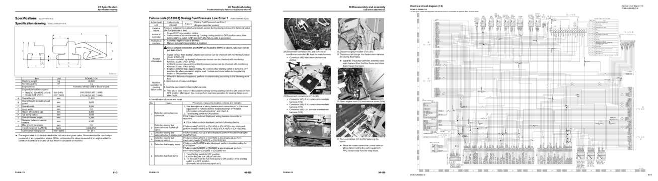
- Specifications, page 70: 01 Specification
- Troubleshooting, page 876: Failure code [CA2881] Dosing Fuel Pressure Low Error 1
- Diagram, page 1,474: 50 Disassembly and assembly
- Foldout diagram, page 1,666: PC490-10, PC490LC-10
Other manuals for this machine
Save 10% on 2 manuals, 15% on 3 or more. Other manuals for the PC490LC-10 are listed below. Editions cover different serial number ranges: check the serial coverage and tick only the ones that match your machine.
Added to your cart. View cart
This is a service manual
Here's how it compares to the other manual types.
Service manual
Factory repair procedures and technical information such as specifications, troubleshooting, and wiring and hydraulic diagrams, for the models and systems the manual covers. See What's inside for its topics.
Operator's manual
Safe operation, controls, maintenance schedules, lubrication points, inspections, and basic checks. Repair procedures are in the service manual.
Parts manual
Illustrated diagrams with factory part numbers for identifying components and ordering parts. Repair procedures are in the service manual.
Engine service manuals are sometimes sold separately, since certain machine models were offered with more than one engine option.
What it's used for
Factory manual for in-house farm and construction shop use. Straightforward, complete, and easy to follow. It contains the OEM information dealership service departments and parts counters use to diagnose problems, identify components, and perform maintenance or repairs correctly.
Service shops and owner/operators who repair their own equipment
Identifying correct parts and seeing how assemblies come apart and go back together
Keeping equipment running with less downtime
Factory manual, 1,682 pages
Quantity one is the manual described above.
Fast free USA shipping
Ships in 1 business day.
60-day returns
Free if the mistake is ours. A manual ordered in error must come back unopened in its shrink-wrap; you pay return shipping and a 20% restocking fee applies. Return policy
Binder not included
Manuals over about 300 pages may need a standard 3-ring binder, which you can buy locally to keep the pages organized for shop use.
Other editions and similar models
Questions about model, serial number, engine coverage or contents? Contact us before purchasing and we'll help confirm it's the right manual. Please verify the manual type, machine model, serial number range and engine coverage before purchasing: manuals ordered in error carry a 20% restocking fee (return policy).