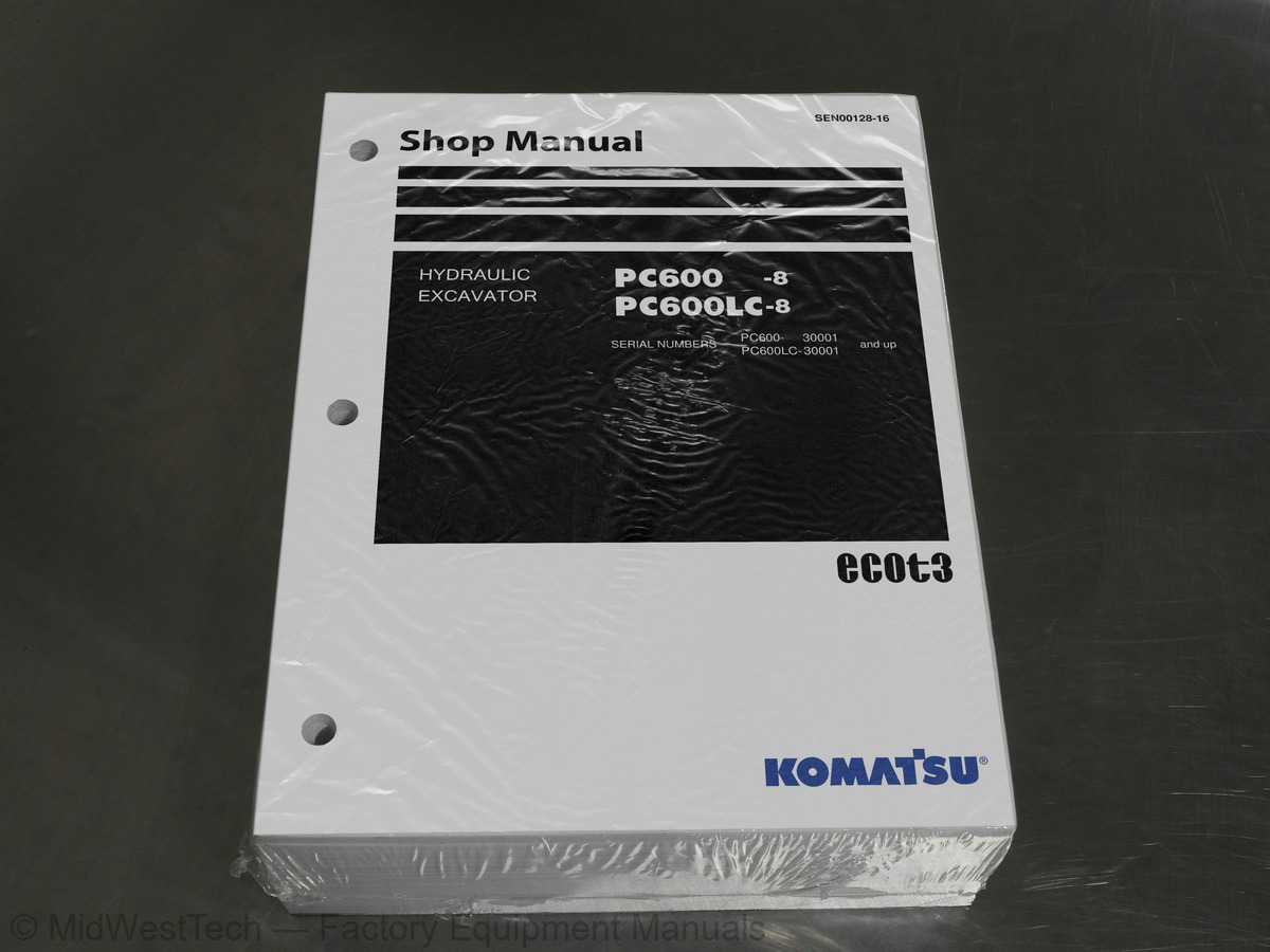
Komatsu PC600-8, PC600LC-8 Hydraulic Excavator Service Manual
1,068 pages · Publication SEN00128-16
Added to your cart. View cart
What's inside
From the manual's own table of contents: 199 sections, 397 entries. See sample pages (PDF, 777 KB)
Show all 199 sections
Hydraulic system, Part 221 topics
- Control valve
- Swing motor
- Swing brake
- Safety valve
- Reverse prevention valve
- Center swivel joint
- Travel motor
- Parking brake
- Brake valve
- Set pressures varying mechanism
- Valve control
- Work equipment, swing PPC valve
- Travel PPC valve
- Service PPC valve
- PPC accumulator
- PPC shuttle valve
- Solenoid valve
- Boom holding valve
- Boom LOWER regeneration valve
- Quick return valve
- Hydraulic cylinder
Work equipment1 topic
- Dimensions of work equipment
Cab and its attachments21 topics
- Air conditioner piping
- Engine control
- Machine control system diagram
- Monitor system
- Sensors
- KOMTRAX system
- Standard value table for engine
- Standard value table for chassis
- Tools for testing, adjusting and troubleshooting
- Measuring engine speed
- Measuring intake air pressure (boost pressure)
- Measuring exhaust gas temperature
- Measuring exhaust gas color
- Adjusting valve clearance
- Measuring compression pressure
- Measuring blow-by pressure
- Measuring engine oil pressure
- Testing EGR valve and bypass valve drive oil pressure
- Handling equipment in fuel circuit
- Releasing remaining pressure in fuel system
- Measuring fuel pressure
Failure code [CA115] Eng Ne and Bkup Speed Sens Error58 topics
- Failure code [CA122] Chg Air Press Sensor High Error
- Failure code [CA123] Chg Air Press Sensor Low Error
- Failure code [CA131] Throttle Sensor High Error
- Failure code [CA132] Throttle Sensor Low Error
- Failure code [CA135] Eng Oil Press Sensor High Error
- Failure code [CA141] Eng Oil Press Sensor Low Error
- Failure code [CA144] Coolant Temp Sens High Error
- Failure code [CA145] Coolant Temp Sens Low Error
- Failure code [CA153] Chg Air Temp Sensor High Error
- Failure code [CA154] Chg Air Temp Sensor Low Error
- Failure code [CA187] Sens Supply 2 Volt Low Error
- Failure code [CA221] Ambient Press Sens High Error
- Failure code [CA222] Ambient Press Sens Low Error
- Failure code [CA227] Sens Supply 2 Volt High Error
- Failure code [CA234] Eng Overspeed
- Failure code [CA238] Ne Speed Sens Supply Volt Error
- Failure code [CA263] Fuel Temp Sensor High Error
- Failure code [CA265] Fuel Temp Sensor Low Error
- Failure code [CA271] IMV/PCV1 Short Error
- Failure code [CA272] IMV/PCV1 Open Error
- Failure code [CA273] PCV2 Short Error
- Failure code [CA274] PCV2 Open Error
- Failure code [CA322] Inj #1 (L#1) Open/Short Error
- Failure code [CA323] Inj #5 (L#5) Open/Short Error
- Failure code [CA324] Inj #3 (L#3) Open/Short Error
- Failure code [CA325] Inj #6 (L#6) Open/Short Error
- Failure code [CA331] Inj #2 (L#2) Open/Short Error
- Failure code [CA332] Inj #4 (L#4) Open/Short Error
- Failure code [CA342] Calibration Code Incompatibility
- Failure code [CA351] Injectors Drive Circuit Error
- Failure code [CA352] Sens Supply 1 Volt Low Error
- Failure code [CA386] Sens Supply 1 Volt High Error
- Failure code [CA441] Battery Voltage Low Error
- Failure code [CA442] Battery Voltage High Error
- Failure code [CA449] Rail Press Very High Error
- Failure code [CA451] Rail Press Sensor High Error
- Failure code [CA452] Rail Press Sensor Low Error
- Failure code [CA553] Rail Press High Error
- Failure code [CA554] Rail Press Sensor In Range Error
- Failure code [CA559] Rail Press Low Error
- Failure code [CA689] Eng Ne Speed Sensor Error
- Failure code [CA731] Eng Bkup Speed Sens Phase Error
- Failure code [CA757] All Persistent Data Lost Error
- Failure code [CA778] Engine Bkup Speed Sensor Error
- Failure code [CA1228] EGR Valve Servo Error 1
- Failure code [CA1625] EGR Valve Servo Error 2
- Failure code [CA1626] BP Valve Sol Current High Error
- Failure code [CA1627] BP Valve Sol Current Low Error
- Failure code [CA1628] Bypass Valve Servo Error 1
- Failure code [CA1629] Bypass Valve Servo Error 2
- Failure code [CA1631] BP Valve Pos Sens High Error
- Failure code [CA1632] BP Valve Pos Sens Low Error
- Failure code [CA1633] KOMNET Datalink Timeout Error
- Failure code [CA1642] EGR Inlet Press Sens Low Error
- Failure code [CA1653] EGR Inlet Press Sens High Error
- Failure code [CA2185] Throt Sens Sup Volt High Error
- Failure code [CA2186] Throt Sens Sup Volt Low Error
- Failure code [CA2249] Rail Press Very Low Error
Hydraulic oil temperature gauge does not display correctly54 topics
- Fuel gauge does not display correctly
- Swing lock monitor does not display correctly
- When monitor switch is operated, nothing is displayed
- Wiper and window washer do not work
- Boom Raise" is not correctly displayed in monitoring function
- Boom Lower" is not correctly displayed in monitoring function
- Arm IN" is not correctly displayed in monitoring function
- Arm OUT" is not correctly displayed in monitoring function
- Bucket CURL" is not correctly displayed in monitoring function
- Bucket DUMP" is not correctly displayed in monitoring function
- Swing" is not correctly displayed in monitoring function
- Travel" is not correctly displayed in monitoring function
- Air conditioner does not work
- Step light does not light up or go off
- Electric grease gun does not operate
- Travel alarm does not sound or does not stop sounding
- Horn does not sound
- Bottom dump does not move
- Before troubleshooting H-mode
- Information in troubleshooting table
- Speed or power of all work equipment, travel, and swing is low
- Engine speed lowers remarkably or engine stalls
- All work equipment, travel, and swing systems do not work
- Abnormal sound is heard from around pump
- Auto-decelerator is not reset
- Boom speed or power is low
- Arm speed or power is low
- Bucket speed or power is low
- Boom does not move
- Arm does not move
- Bucket does not move
- Hydraulic drift of work equipment is large
- Time lag of work equipment is large
- Power max. function does not operate or stop
- Machine push-up function does not operate or stop
- When arm and boom, bucket are operated simultaneously, boom, bucket speed is low
- travel speed is low
- When arm and swing are operated simultaneously, swing speed is low
- Machine deviates in one direction
- Machine deviates largely at start
- Travel deviation is large during compound operation
- Travel speed or power is low
- Machine does not travel (only one track)
- Travel speed does not change
- Upper structure does not swing
- Swing speed or acceleration is low
- Upper structure overruns excessively when it stops swinging
- Large shock is made when upper structure stops swinging
- Large abnormal sound is made when upper structure stops swinging
- Hydraulic drift of swing is large
- Method of using troubleshooting chart
- Starting performance is poor
- Engine does not start
- Engine does not pick up smoothly
Disassembly and assembly of control valve assembly43 topics
- Disassembly and assembly of main control valve assembly
- Removal and installation of swing motor assembly
- Removal and installation of center swivel joint assembly
- Disassembly and assembly of center swivel joint assembly
- Disassembly and assembly of work equipment PPC valve assembly
- Disassembly and assembly of travel PPC valve assembly
- Disassembly and assembly of hydraulic cylinder assembly
- Disassembly and assembly of grease gun assembly
- Removal and installation of bucket cylinder assembly (Backhoe specification)
- Removal and installation of bucket cylinder assembly (Loading shovel specification)
- Removal and installation of arm cylinder assembly (Backhoe specification)
- Removal and installation of arm cylinder assembly (Loading shovel specification)
- Removal and installation of boom cylinder assembly (Backhoe specification)
- Removal and installation of boom cylinder assembly (Loading shovel specification)
- Removal and installation of bottom dump cylinder assembly (Loading shovel specification)
- Removal and installation of bucket assembly (Backhoe specification)
- Removal and installation of bucket assembly (Loading shovel specification)
- Removal and installation of arm assembly (Backhoe specification)
- Removal and installation of arm assembly (Loading shovel specification)
- Removal and installation of boom assembly (Backhoe specification)
- Removal and installation of boom assembly (Loading shovel specification)
- Removal and installation of work equipment (Backhoe specification)
- Removal and installation of work equipment (Loading shovel specification)
- Removal and installation of operator’s cab
- Removal and installation of operator’s cab glass (stuck glass)
- Removal and installation of front window assembly
- Removal and installation of air conditioner unit assembly
- Removal and installation of engine controller assembly
- Removal and Installation of KOMTRAX terminal assembly
- Removal and installation of pump controller assembly
- Removal and installation of monitor assembly
- Hydraulic circuit diagram (1/4) (Backhoe specification)
- Hydraulic circuit diagram (2/4) (ATT specification)
- Hydraulic circuit diagram (3/4) (Loading shovel specification)
- Hydraulic circuit diagram (4/4) (Loading shovel specification)
- Electrical circuit diagram (1/6)
- Electrical circuit diagram (2/6)
- Electrical circuit diagram (3/6)
- Electrical circuit diagram (4/6)
- Electrical circuit diagram (5/6)
- Electrical circuit diagram (6/6)
- Connector arrangement diagram
- Electrical circuit diagram for air conditioner
Inside this manual
Real pages from this service manual (1,068 pages). Open the sample pages (PDF, 776 KB)
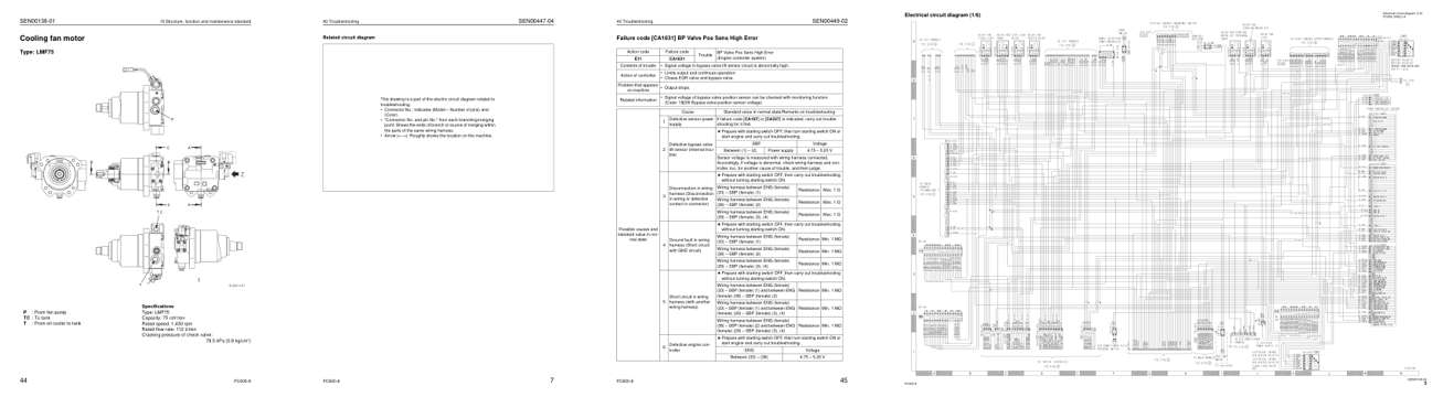
- Specifications, page 157: 10 Structure, function and maintenance standard
- Diagram, page 461: Related circuit diagram
- Troubleshooting, page 605: Failure code [CA1631] BP Valve Pos Sens High Error
- Foldout diagram: Electrical circuit diagram (1/6)
Other manuals for this machine
Save 10% on 2 manuals, 15% on 3 or more. Other manuals for the PC600-8, PC600LC-8 are listed below. Editions cover different serial number ranges: check the serial coverage and tick only the ones that match your machine.
Added to your cart. View cart
This is a service manual
Here's how it compares to the other manual types.
Service manual
Factory repair procedures and technical information such as specifications, troubleshooting, and wiring and hydraulic diagrams, for the models and systems the manual covers. See What's inside for its topics.
Operator's manual
Safe operation, controls, maintenance schedules, lubrication points, inspections, and basic checks. Repair procedures are in the service manual.
Parts manual
Illustrated diagrams with factory part numbers for identifying components and ordering parts. Repair procedures are in the service manual.
Engine service manuals are sometimes sold separately, since certain machine models were offered with more than one engine option.
What it's used for
Factory manual for in-house farm and construction shop use. Straightforward, complete, and easy to follow. It contains the OEM information dealership service departments and parts counters use to diagnose problems, identify components, and perform maintenance or repairs correctly.
Service shops and owner/operators who repair their own equipment
Identifying correct parts and seeing how assemblies come apart and go back together
Keeping equipment running with less downtime
Factory manual, 1,068 pages
Quantity one is the manual described above.
Fast free USA shipping
Ships in 1 business day.
60-day returns
Free if the mistake is ours. A manual ordered in error must come back unopened in its shrink-wrap; you pay return shipping and a 20% restocking fee applies. Return policy
Binder not included
Manuals over about 300 pages may need a standard 3-ring binder, which you can buy locally to keep the pages organized for shop use.
Questions about model, serial number, engine coverage or contents? Contact us before purchasing and we'll help confirm it's the right manual. Please verify the manual type, machine model, serial number range and engine coverage before purchasing: manuals ordered in error carry a 20% restocking fee (return policy).