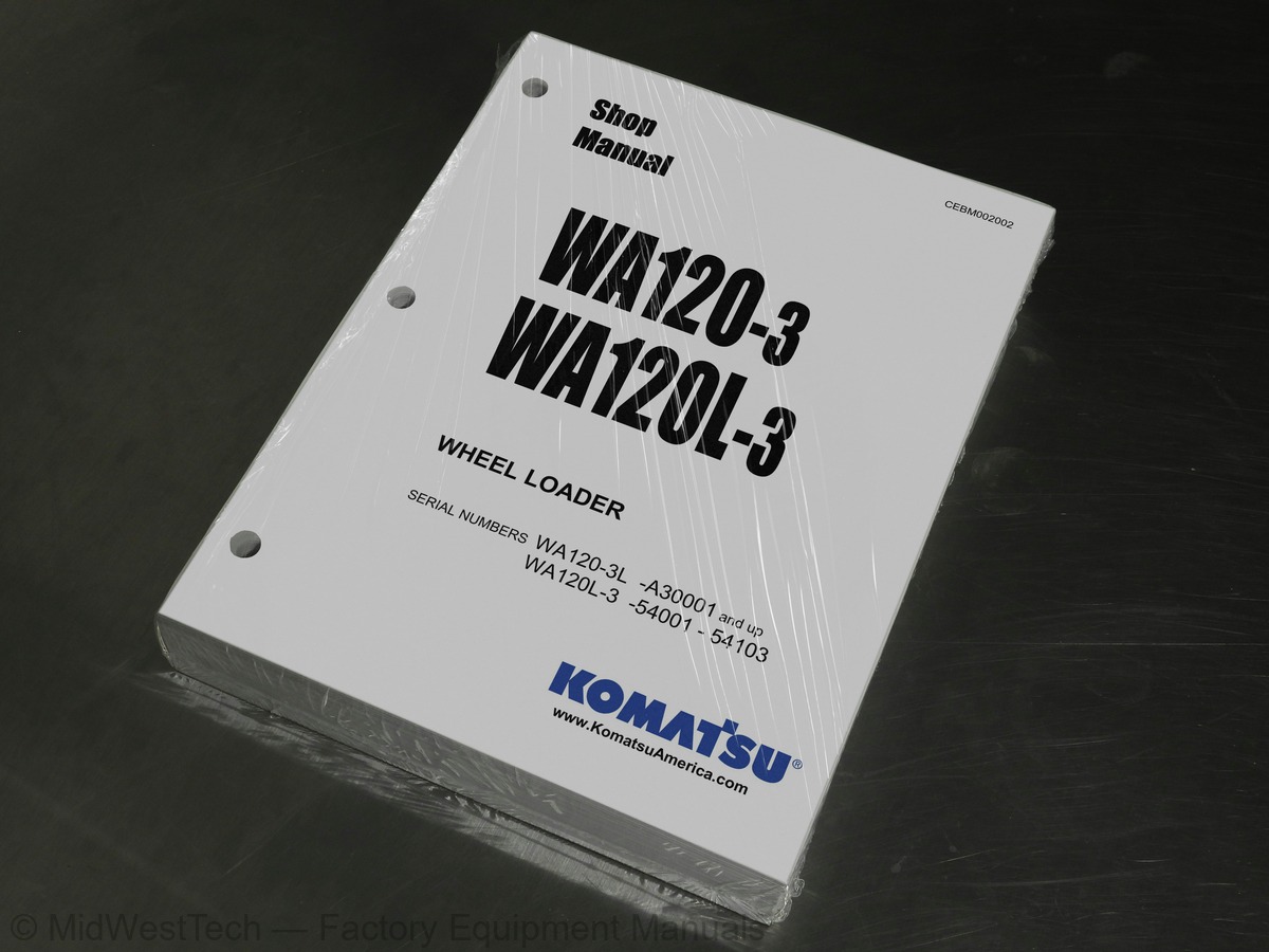
Komatsu WA120-3L, WA120L-3 Wheel Loader Service Manual
586 pages · Publication CEBM002002
Added to your cart. View cart
- Models
- WA120-3L, WA120L-3
- Serial coverage
- WA120-3L A30001 and up, WA120L-3 54001-54103
- Manual type
- Service Manual
- Pages
- 586
- Publication
- CEBM002002
- Condition
- Brand new
What's inside
From the manual's own table of contents: 3 sections, 213 entries. See sample pages (PDF, 513 KB)
General6 topics
- GENERAL
- STRUCTURE AND FUNCTION
- TESTING AND ADJUSTMENT
- DISASSEMBLY AND ASSEMBLY
- MAINTENANCE STANDARD
- OTHER
STRUCTURE AND FUNCTION156 topics
- AXLE
- FRONT AXLE
- FRONT DIFFERENTIAL
- REAR AXLE
- REAR DIFFERENTIAL
- Outline
- TORQUE PROPORTIONING DIFFERENTIAL
- FINAL DRIVE
- AXLE MOUNT
- CENTER HINGE PIN
- STEERING PIPING
- STEERING COLUMN
- PRIORITY VALVE
- STEERING VALVE (ORBIT-ROLL)
- Operation
- Steering wheel at neutral
- Steering wheel turned (turning to left)
- CONNECTION BETWEEN HAND PUMP AND SLEEVE
- BRAKE PIPING
- BRAKE CONTROL
- BRAKE BOOSTER
- BRAKE
- PARKING BRAKE CONTROL
- PARKING BRAKE
- HYDRAULIC PIPING
- WORK EQUIPMENT HYDRAULIC SYSTEM DIAGRAM
- WORK EQUIPMENT HYDRAULIC CIRCUIT DIAGRAM
- HYDRAULIC TANK
- OIL FILTER BYPASS VALVE
- BREATHER
- MAIN CONTROL VALVE
- 2-SPOOL VALVE
- 3-SPOOL VALVE
- RELIEF VALVE
- SAFETY VALVE (WITH SUCTION)
- SUCTION VALVE
- Boom and bucket spool at NEUTRAL position
- Boom spool at RAISE position
- Boom spool at LOWER position
- Boom spool at FLOAT position
- STRUCTURE AND FUNCTION
- Bucket spool at TILT BACK position
- Bucket spool at DUMP position
- WORK EQUIPMENT LEVER LINKAGE
- WORK EQUIPMENT LINKAGE
- BUCKET
- BUCKET POSITIONER AND BOOM KICK-OUT
- BUCKET POSITIONER
- BOOM KICK-OUT
- PROXIMITY SWITCH
- OPERATION OF THE PROXIMITY SWITCH
- Bucket TILT BACK switch
- Boom RAISE switch
- Action of the proximity switch
- ROPS CAB
- AIR CONDITIONER
- AIR CONDITIONER AND HEATER PIPING
- ELECTRIC CIRCUIT DIAGRAM
- E.C.S.S. (ELECTRONIC CONTROLLED SUSPENSION SYSTEM)
- E.C.S.S. HYDRAULIC, ELECTRICAL CIRCUIT DIAGRAM
- ELECTRICAL WIRING ILLUSTRATION
- ELECTRICAL WIRING DIAGRAM (1/3)
- CENTRAL PANEL (CLUSTER GAUGE)
- SENSOR
- ENGINE OIL PRESSURE
- BRAKE OIL LEVEL
- ENGINE STARTING CIRCUIT
- ENGINE STOP CIRCUIT
- AUTOMATIC PREHEATING CIRCUIT
- QUICK HEATING SYSTEM (Q.H.S.)
- Q.H.S. CONTROLLER
- HEATER RELAY
- RIBBON HEATER
- Q.H.S. WATER TEMPERATURE SENSOR
- ELECTRICAL TRANSMISSION CONTROL
- COMBINATION SWITCH
- TRANSMISSION CUT-OFF FUNCTION
- PARKING BRAKE FUNCTION
- KICK-DOWN SWITCH
- KICK DOWN ELECTRIC CIRCUIT DIAGRAM
- KICK-DOWN SWITCH OPERATED
- KICK-DOWN SWITCH ACTUATION - CANCELED (1)
- KICK-DOWN SWITCH ACTUATION - CANCELED (2)
- KICK-DOWN SWITCH ACTUATION - CANCELED (3)
- TESTING AND ADJUSTING
- Bucket cannot be pushed with boom cylinder (bucket floats)
- Excessive hydraulic drift of boom
- Boom shakes during operation
- Boom drops momentarily when control lever is operated from HOLD to RAISE
- Bucket does not tilt back
- Bucket movement is slow or tilt-back lacks power
- Bucket movement becomes slow during tilt-back operation
- Bucket cannot be pushed with bucket cylinder
- Excessive hydraulic drift of bucket
- Bucket shakes during loading operation (Main control valve at HOLD)
- Bucket dumps momentarily when control lever is operated from HOLD to TILT
- Boom, bucket control levers are heavy or do not move smoothly
- AIR CONDITIONER / HEATER (EAGLE)
- TROUBLESHOOTING
- WIRING DIAGRAM
- POINTS TO REMEMBER WHEN TROUBLESHOOTING
- SEQUENCE OF EVENTS IN TROUBLESHOOTING
- PRECAUTIONS WHEN CARRYING OUT MAINTENANCE
- PRECAUTIONS WHEN HANDLING ELECTRIC EQUIPMENT
- POINTS TO REMEMBER WHEN TROUBLESHOOTING ELECTRIC CIRCUITS
- POINTS TO REMEMBER WHEN HANDLING HYDRAULIC EQUIPMENT
- CHECKS BEFORE TROUBLESHOOTING
- HANDLING CONNECTORS
- PRECAUTIONS WHEN TROUBLESHOOTING
- PREVENTING RECURRENCE OF TROUBLE
- METHOD OF USING TROUBLESHOOTING CHARTS
- Category of troubleshooting code number
- Method of using troubleshooting table for each troubleshooting mode
- Using troubleshooting chart for engine related failure
- (Starting always takes time)
- S-2 Engine does not start
- S-3 Engine does not pick up smoothly (Follow up is poor)
- S-4 Engine stops during operations
- S-5 Engine does not rotate smoothly (hunting)
- S-6 Engine lacks output (no power)
- S-7 Exhaust gas is black (incomplete combustion)
- S-8 Oil consumption is excessive (or exhaust gas is blue)
- S-9 Oil becomes contaminated quickly
- S-10 Fuel consumption is excessive
- S-11 Oil is in cooling water, or water spurts back, or water level goes down
- S-12 Oil pressure lamp lights up (drop in oil pressure)
- S-13 Oil level rises
- S-14 Water temperature becomes too high
- S-15 Abnormal noise is made
- S-16 Vibration is excessive
- POWER TRAIN
- T-1 Machine does not start
- T-2 Travel speed is slow, thrusting power is weak, lacks power on slopes
- T-3 Excessive shock when starting machine or shifting gear
- T-4 Excessive time lag when starting machine or shifting gear
- T-5 Torque converter oil temperature is high
- STEERING SYSTEM
- S-1 Steering wheel does not turn
- S-2 Steering is heavy
- S-3 Steering wheel shakes or there is excessive shock
- S-4 Deviates to one side when traveling
- S-5 Turning radius is different between left and right
- S-6 Excessive shock to machine when steering wheel is turned fully to left or right
- BRAKE SYSTEM
- A-1 Brakes do not work or braking effect is poor
- A-2 Brake is not released, brake drags
- WORK EQUIPMENT
- Boom does not rise
- Boom movement is slow or boom lacks lifting power
- When boom is raised, it moves slowly at a certain height
- H-10 Bucket movement becomes slow during tilt-back operation
- H-11 Bucket cannot be pushed with bucket cylinder
- H-12 Excessive hydraulic drift of bucket
- H-13 Bucket shakes during loading operation (Main control valve at HOLD)
- H-14 Bucket dumps momentarily when control lever is operated from HOLD to TILT
- H-15 Boom, bucket control levers are heavy or do not move smoothly
DISASSEMBLY AND ASSEMBLY46 topics
- CYLINDER HEAD
- REMOVAL
- INSTALLATION
- RADIATOR
- ENGINE
- ENGINE HOOD
- EXHAUST MUFFLER
- AIR CLEANER
- TORQUE CONVERTER CHARGING PUMP
- TORQUE CONVERTER, TRANSMISSION
- TORQUE CONVERTER ASSEMBLY
- DISASSEMBLY
- ASSEMBLY
- TRANSMISSION
- TRANSMISSION CLUTCH PACK
- DISASSEMBLY OF 1ST, REVERSE CLUTCH
- DISASSEMBLY OF FORWARD, 2ND CLUTCH PACK
- DISASSEMBLY OF 3RD, 4TH CLUTCH PACK
- ASSEMBLY OF CLUTCH PACK
- ASSEMBLY OF 1ST, REVERSE CLUTCH PACK
- ASSEMBLY OF FORWARD, 2ND CLUTCH PACK
- ASSEMBLY OF 3RD, 4TH CLUTCH PACK
- TRANSMISSION CONTROL VALVE
- DISASSEMBLY AND ASSEMBLY
- TRANSMISSION SOLENOID VALVE
- TRANSMISSION ACCUMULATOR VALVE
- DRIVE SHAFT
- DIFFERENTIAL
- AXLE HOUSING
- STEERING VALVE
- DISASSEMBLY OF ROTOR
- DISASSEMBLY OF CONTROL SIDE
- ASSEMBLY OF ROTOR
- STEERING CYLINDER
- HYDRAULIC FILTER
- HYDRAULIC STEERING PUMP
- BUCKET CYLINDER
- BOOM CYLINDER
- HYDRAULIC CYLINDERS
- FUEL TANK
- COUNTERWEIGHTS
- REMOVAL OF LEFT AND RIGHT SIDE COUNTERWEIGHTS
- INSTALLATION OF LEFT AND RIGHT SIDE COUNTERWEIGHTS
- REMOVAL OF REAR COUNTERWEIGHT
- INSTALLATION OF REAR COUNTERWEIGHT
- INSTRUMENT PANEL
MAINTENANCE STANDARD2 topics
- HYDRAULIC PUMP
- HYDRAULIC CYLINDER
Inside this manual
Real pages from this service manual (586 pages). Open the sample pages (PDF, 513 KB)
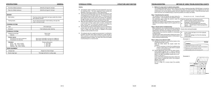
- Specifications, page 26: SPECIFICATIONS
- Diagram, page 116: HYDRAULIC PIPING
- Troubleshooting, page 260: TROUBLESHOOTING
Other manuals for this machine
Save 10% on 2 manuals, 15% on 3 or more. Other manuals for the WA120L-3 are listed below. Editions cover different serial number ranges: check the serial coverage and tick only the ones that match your machine.
Added to your cart. View cart
This is a service manual
Here's how it compares to the other manual types.
Service manual
Factory repair procedures and technical information such as specifications, troubleshooting, and wiring and hydraulic diagrams, for the models and systems the manual covers. See What's inside for its topics.
Operator's manual
Safe operation, controls, maintenance schedules, lubrication points, inspections, and basic checks. Repair procedures are in the service manual.
Parts manual
Illustrated diagrams with factory part numbers for identifying components and ordering parts. Repair procedures are in the service manual.
Engine service manuals are sometimes sold separately, since certain machine models were offered with more than one engine option.
What it's used for
Factory manual for in-house farm and construction shop use. Straightforward, complete, and easy to follow. It contains the OEM information dealership service departments and parts counters use to diagnose problems, identify components, and perform maintenance or repairs correctly.
Service shops and owner/operators who repair their own equipment
Identifying correct parts and seeing how assemblies come apart and go back together
Keeping equipment running with less downtime
Factory manual, 586 pages
Quantity one is the manual described above.
Fast free USA shipping
Ships in 1 business day.
60-day returns
Free if the mistake is ours. A manual ordered in error must come back unopened in its shrink-wrap; you pay return shipping and a 20% restocking fee applies. Return policy
Binder not included
Manuals over about 300 pages may need a standard 3-ring binder, which you can buy locally to keep the pages organized for shop use.
Questions about model, serial number, engine coverage or contents? Contact us before purchasing and we'll help confirm it's the right manual. Please verify the manual type, machine model, serial number range and engine coverage before purchasing: manuals ordered in error carry a 20% restocking fee (return policy).