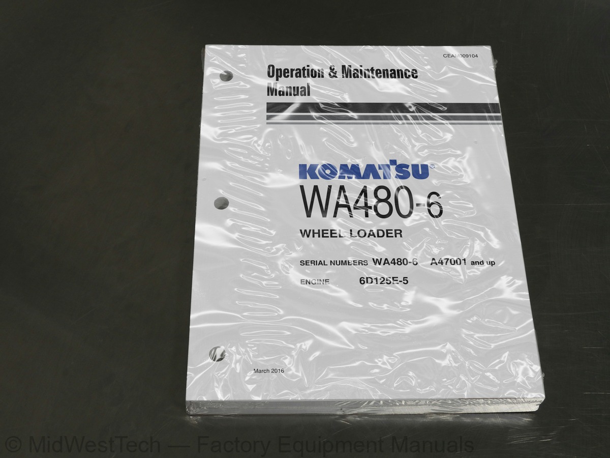
Komatsu WA480-6 Wheel Loader Operation & Maintenance Manual
429 pages · Publication CEAM009104
Added to your cart. View cart
- Models
- WA480-6
- Serial coverage
- WA480-6 A47001 and up
- Manual type
- Operation & Maintenance Manual
- Pages
- 429
- Publication
- CEAM009104
- Condition
- Brand new
What's inside
From the manual's own table of contents: 537 topics. See sample pages (PDF, 430 KB)
- FOREWORD
- SAFETY INFORMATION
- APPROVED AND NON-APPROVED USES
- Approved Functions
- Non-Approved Functions
- VISIBILITY STANDARD
- Visibility in Immediate Area
- 12-M Radius Visibility
- Front/Rear, Left/Right Directions of Machine
- Machine Serial Number/Product Identification Number (PIN)
- Engine Serial Number, EPA Regulations
- Position of Service Meter
- Serial Numbers and Dealer Information
- SAFETY AND WARNING DECALS
- Location of Safety Decals
- Safety Labels
- GENERAL SAFETY RULES AND PRECAUTIONS
- General Safety Rules
- General Safety at Job Site
- Working on Loose Ground
- Safety Features
- Personal Protective Equipment
- Keep Machine Clean
- Fire and Explosion Prevention
Show all 537 topics
- Fire Caused by Fuel, Oil, Antifreeze, or Window Washer Fluid
- Fire Caused by Accumulation of Flammable Material
- Fire Coming from Electric Wiring
- Fire Coming from Hydraulic Line
- Windshield Washer Fluid
- Action If Fire Occurs
- Fire Extinguisher and First Aid Kit
- Fire Prevention and Suppression
- Fire Prevention Steps
- Fixed Fire Detection System
- Fixed Fire Suppression System
- Fire Prevention Procedures
- Precautions When Cleaning Cab Glass
- Dust Hazards Precautions
- Keep Operator's Cab Clean
- Unauthorized Modifications
- Leaving Operator’s Compartment
- Mounting and Dismounting
- Crush or Pinch Point Dangers
- Inside Operator’s Compartment
- Precautions When Using ROPS
- Emergency Escape From Operator's Cab
- PRECAUTIONS BEFORE STARTING OPERATIONS
- Pre-Operational Checks
- Starting Your Work Operations
- Work Site Hazards
- Avoiding Dangerous Situations
- Working Clearances
- Operating on Snow or Icy Surfaces
- Precautions in Cold Areas
- Asbestos Hazard Alert
- RULES FOR ROAD TRAVEL
- Traveling in Reverse
- Travel on Slopes
- Parking the Machine
- PRECAUTIONS DURING MAINTENANCE OPERATIONS
- Warning Tags
- Equipment Storage
- Working Under the Machine
- Using Drop Lamps
- Keeping the Machine Clean
- HANDLING TIRES
- Precautions When Storing Tires
- PERFORMING GENERAL MAINTENANCE PROCEDURES
- Running the Engine During Maintenance
- Proper Tools
- Engine System High-Voltage
- Welding, Grinding or Cutting
- When Using Hammer
- Refueling the Machine
- Cooling System Precautions
- Battery Precautions
- Starting the Machine
- High-Pressure Hoses
- Safety Handling High-Pressure Hoses
- Precaution For High Fuel Pressure
- High Temperature Areas
- Disposal of Waste Materials
- Inflating Tires
- Accumulator
- Critical Parts
- TRANSPORTING THE MACHINE
- Loading and Unloading a Trailer
- Loading Machine
- TOWING THE MACHINE
- GENERAL VIEW
- General View Of Machine
- General View of Controls and Gauges
- Machine Monitor
- Switch Panel
- EXPLANATION OF COMPONENTS
- Types of Warnings
- Emergency Stop
- Caution
- Mistaken Operation
- Inspection and Maintenance
- Central Warning Lamp
- Character Display Portion
- Service Meter
- Action Code Display
- Failure Code Display
- Filter, Oil Replacement Time Display
- Emergency Stop Items
- Brake Oil Pressure Caution Lamp
- Engine Oil Pressure Caution Lamp
- Battery Charge Circuit Caution Lamp
- Steering Oil Pressure Caution Lamp (if equipped)
- Caution Items
- Brake Oil Temperature Caution Lamp
- Torque Converter Oil Temperature Caution Lamp
- Engine Coolant Temperature Caution Lamp
- Hydraulic Oil Temperature Caution Lamp
- Fuel Level Caution Lamp
- Inspection and Maintenance Items
- Radiator Coolant Level Caution Lamp
- Engine Oil Level Caution Lamp
- Battery Electrolyte Level Caution Lamp
- Maintenance Caution Lamp
- Air Cleaner Clogging Caution Lamp
- Water Separator Caution Lamp
- Transmission Oil Filter Clogging Caution Lamp
- Pilot Display Portion
- Parking Brake Pilot Lamp
- Cooling Fan Reverse Rotation Pilot Lamp
- Emergency Steering Pilot Lamp
- Power Mode Pilot Lamp (P Mode)
- Preheating Pilot Lamp
- Semi-Auto Digging Pilot Lamp
- Auto-Greasing Pilot Lamp
- Joystick Pilot Lamp (if equipped)
- Directional Selector Pilot Lamp
- Economy Operation Display Lamp
- Shift Indicator
- Auto-Shift Pilot Lamp
- Torque Converter Lockup Pilot Light (if equipped)
- Shift Hold Pilot Lamp
- Shift Lever Position Pilot Lamp
- Turn Signal Pilot Lamp
- Head Lamp High-Beam Pilot Lamp
- Meter Display Portion
- Torque Converter Oil Temperature Gauge
- Engine Coolant Temperature Gauge
- Hydraulic Temperature Gauge
- Fuel Gauge
- Speedometer
- Meter Display Pilot Lamp
- OTHER FUNCTIONS OF MACHINE MONITOR
- Overall Menu
- Displaying Odometer
- Resetting Filter, Oil Replacement Time
- Entering Telephone Number
- Selecting Language
- Adjusting Monitor Brightness
- Switching Travel Speed/Engine Speed Display
- Switching Travel Speed/Engine Speed Display/Non-Display
- SWITCHES AND CONTROLS
- Ignition Switch
- Power Mode Selector Switch
- Transmission Shift Mode Selector Switch
- Transmission Cutoff Switch
- Transmission Cutoff Set Switch
- Lamp Switch
- Turn Signal Lever
- Dimmer Switch
- Horn Button
- Hazard Lamp Switch
- Parking Brake Switch
- Front Working Lamp Switch
- Rear Working Lamp Switch
- Machine Monitor Mode Selector Switch 1
- Machine Monitor Mode Selector Switch 2
- Kickdown Switch
- Hold Switch
- Front Wiper Switch
- Rear Wiper Switch
- Cigarette Lighter
- Room Lamp Switch
- Rear Heated Wire Glass Switch
- ECSS Switch
- Emergency Steering Switch (if equipped)
- Cooling Fan Reverse Rotation Switch (If Equipped)
- Cooling Fan Auto-Reverse Rotation Switch (If Equipped)
- Conditions for Switching Fan Rotation
- Torque Converter Lockup Switch (if equipped)
- CONTROL LEVERS, PEDALS
- Gearshift Lever
- Directional Lever
- Gearshift Lever Stopper
- Work Equipment Lock Lever
- Bucket Control Lever
- Lift Arm Control Lever
- Brake Pedals
- Accelerator Pedal
- SECURITY LOCKS AND SAFETY FEATURES
- Steering Tilt Lock Lever
- Frame Lock Bar
- Cap with Lock
- Fuel Tank Filler Port Cap
- Back-Up Alarm
- MACHINE FEATURES
- Towing Pin
- Grease Pump
- Cab Door
- Emergency Escape Right Door
- Left Cab Door, Door Open Lock
- Left Cab Door, Knob
- Left Cab Door, Handle
- Left Cab Sliding Window (Lock Release Knob)
- Cab Wiper
- ELECTRICAL
- Power Outlet
- Fuses
- Fuse Capacity and Name of Circuit
- Slow-Blow Fuse
- WORK OPERATIONS
- Walk-Around Check
- Precautions Before Starting Work Operations
- Check Before Starting Engine
- Check Machine Monitor
- Check Coolant Level, Add Coolant
- Check Oil Level in Engine Oil Pan, Add Oil
- Check Water Separator, Drain Water
- Check Air Cleaner
- Electric Air Cleaner Clogging Sensor
- Check Fuel Level, Add Fuel
- Check Electric Wiring
- Check Inflation Pressure of Tires
- Check Condition of Window Washer Spray
- Check Wiping Efficiency of Wiper
- Check Horn
- Check Defroster Function
- Check Locks
- Check Emergency Exit
- Adjustments
- Adjusting Seat
- Removing or Installing Headrest
- Adjusting Seat Belt
- Adjusting Lever Stand
- Adjusting Mirrors
- Final Checks Before Starting Engine
- Starting Engine
- Normal Starting
- Starting in Cold Weather
- Automatic Warming-Up Operation
- Operations and Checks After Starting Engine
- Checks After Starting Engine
- Breaking in the Machine
- Normal Operation
- Stopping Engine
- Check After Stopping Engine
- Moving the Machine (Directional, Speed), Stopping the Machine
- Moving the Machine
- Changing Gear Speed
- Changing Direction
- Automatic Shift
- Stopping the Machine
- Transmission Cut-Off Function
- Adjusting Transmission Cut-Off Position
- Canceling Transmission Cut-Off Position
- Stopping When Transmission Cut-Off Is On
- Turning
- Emergency Steering (if equipped)
- Emergency Steering Self-Check Function
- Operation of Work Equipment
- Work Possible Using Wheel Loader
- Digging Operations
- Loading Piled Soil or Blasted Rock
- Digging and Loading on Level Ground
- Leveling Operations
- Pushing Operations
- Load and Carry Operations
- Precautions for Using Load and Carry Method
- Loading Operations
- Cross-Drive Loading
- V-Shape Loading
- Precautions When Piling Up Loads
- Preparations for Loading, Gathering Rocks
- Approaching Facing
- Digging
- Traveling in Reverse After Excavation
- Approaching Dump Truck
- Loading Dump Truck
- Reversing Away From Dump Truck
- Precautions During Work Operations
- Piling Up Loads
- Handling Blasted Rock
- Loosened Boulders
- Pit Excavation
- Cutting Face Operations
- Switching Between Forward and Reverse
- Turning When Tires Are Stationary
- If Wheel Brake Does Not Work
- Permissible Water Depth
- Lower the Center of Gravity when Turning
- Driving Up or Down Slopes
- Driving the Machine
- Braking Function
- Adjusting Work Equipment
- Bucket Level Indicator
- Adjusting Boom Kick-Out
- Adjusting Bucket Positioner
- Measuring Dump Angle
- Measuring Bucket Dump Angle
- Measuring Coupler Dump Angle
- Checks After Completion of Operation
- Before Stopping Engine
- After Stopping Engine
- Locking the Machine
- Precautions When Handling Tires
- Tire Pressure
- TRANSPORTATION
- Transportation Procedure
- Loading and Unloading Trailers
- Securing Machine
- Unloading Machine
- LIFTING MACHINE
- Lifting Position
- Lifting Procedure
- COLD WEATHER OPERATION
- Precautions for Low Temperature
- Fuel and Lubricants
- Coolant
- Battery
- Precautions After Completion of Work
- After Cold Weather
- LONG-TERM STORAGE
- Before Storage
- During Storage
- After Storage
- AUTOMATIC AIR CONDITIONER
- Control Panel
- Main Power Switch
- Fan Switch
- Air Conditioner Switch
- Auto Switch
- Temperature Switch
- FRESH/RECIRC Selector Switch
- Mode Selector Switch
- Method of Operation
- Cooling Operation
- Heating Operation
- Drying-Heating and Demisting Operation
- When Not Using the Air Conditioner Regularly
- Precautions When Using Air Conditioner
- Cool Box
- KOMTRAX
- Basic Precautions
- TROUBLESHOOTING
- When Machine Runs Out of Fuel
- When Engine Can Be Used
- When Engine Cannot Be Used
- Releasing Parking Brake
- Emergency Travel Operation
- If Battery is Discharged
- Precautions
- Removal and Installation of Battery
- Precautions for Charging Battery
- Starting Engine With Booster Cables
- Precautions When Connecting or Disconnecting Booster Cable
- Connecting Booster Cable
- Disconnecting Booster Cable
- Lowering Work Equipment When Engine Has Stopped
- Other Troubleshooting
- Electrical System
- Chassis
- Engine
- GUIDES TO MAINTENANCE
- Check Service Meter
- Komatsu Genuine Replacement Parts
- Komatsu Genuine Oils
- Always Use Clean Washer Fluid
- Always Use Clean Oil And Grease
- Checking For Foreign Materials In Drained Oil And On Filters
- Fuel Strainer
- Welding Instructions
- Do Not Drop Things Inside Machine
- Dusty Work Sites
- Avoid Mixing Oil
- Locking Inspection Covers
- Bleeding Air From Hydraulic Circuit
- Precautions When Installing Hydraulic Hoses
- Checks After Inspection and Maintenance
- OUTLINES OF SERVICE
- Handling Oil, Fuel, Coolant, And Performing Oil Clinic
- Fuel
- Coolant and Water for Dilution
- Grease
- Storing Oil and Fuel
- Filters
- Performing KOWA (Komatsu Oil Wear Analysis)
- KOWA Analysis Items
- Oil Sampling
- Outline of Electric System
- WEAR PARTS
- Wear Parts List
- RECOMMENDED FUEL, COOLANT, AND LUBRICANT
- Fuel, Coolant, and Lubricant Ambient Temperature Chart
- Recommended Brands, Other Than Komatsu Genuine Oil
- Biodiesel Usage
- Biodiesel Recommendation for Komatsu Engines
- Biodiesel Terminology
- Certification and Standards
- Warranty and Use of Biodiesel Fuel in Komatsu Engines
- Requirements for Using Biodiesel Fuel in Komatsu Engines
- Properties of Biodiesel
- Komatsu Biodiesel Blend Specification for B5 to B20
- Summary of Recommendations
- STANDARD TIGHTENING TORQUES FOR BOLTS AND NUTS
- Torque List
- PERIODIC REPLACEMENT OF SAFETY CRITICAL PARTS
- Safety Critical Parts List
- MAINTENANCE SCHEDULE CHART
- SERVICE PROCEDURE
- Initial 250 Hours Service
- Initial 1000 Hours Service
- When Required
- Clean, Replace Air Cleaner Element
- Clean Inside of Cooling System
- Check Transmission Oil, Add Oil
- Check Axle Oil Level, Add Oil
- Clean Axle Case Breather
- Clean Air Conditioner Condenser
- Check Window Washing Fluid Level, Add Fluid
- Clean Radiator Fins and Cooler Fins
- Turn, Replace Bolt-On Cutting Edge
- Replace Bucket Teeth
- Check Air Conditioner
- Replace Slow-Blow Fuse
- Check Function of Accumulator
- Select Tires
- Check Tire Pressure
- Clean, Replace Fuel Breather Filter
- Check Before Starting
- Every 50 Hours Service
- Drain Water, Sediment from Fuel Tank
- Every 100 Hours Service
- Lubricate Rear Axle Pivot Pin
- Check Oil Level in Hydraulic Tank, Add Oil
- Clean Element in Air Conditioner Fresh Air Filter
- Every 250 Hours Service
- Check Battery Electrolyte Level
- Check Parking Brake
- Check Alternator Belt Tension, Adjust
- Check Air Conditioner Compressor Belt Tension, Adjust
- Check for Loose Wheel Hub Nuts, Tighten
- Clean Element in Air Conditioner Recirculation Filter
- Check Function of Brake Accumulator
- Lubricating
- Every 500 Hours Service
- Change Oil in Engine Oil Pan, Replace Engine Oil Filter Cartridge
- Replace Fuel Prefilter Cartridge
- Every 1000 Hours Service
- Replace Fuel Main Filter Cartridge
- Change Oil in Transmission Case, Replace Oil Filter Cartridge, Clean Strainer
- Clean Transmission Case Breather
- Replace Corrosion Resistor Cartridge
- Check Engine Air Intake Piping Clamps for Looseness
- Every 2000 Hours Service
- Change Oil in Hydraulic Tank, Replace Hydraulic Filter Element
- Replace Hydraulic Tank Breather Element
- Change Axle Oil
- Replace Element in Air Conditioner Recirculation Filter, Fresh Air Filter
- Check Brake Disc Wear
- Check Function of PPC Accumulator
- Check Alternator
- Check Engine Valve Clearance, Adjust
- Check Starting Motor
- Check Vibration Damper
- Every 4000 Hours Service
- Check Water Pump
- Check Air Conditioner Compressor, Adjust
- Check for Loose Engine High-Pressure Piping Clamps, Hardening of Rubber
- Check for Missing Fuel Spray Prevention Cap, Hardening of Rubber
- Every 8000 Hours Service
- Replace High-Pressure Piping Clamps
- Replace Fuel Spray Prevention Cap
- SPECIFICATIONS
- JOYSTICK STEERING SYSTEM
- Structure and Function
- Components
- Shift UP, Shift DOWN Switches
- Directional Selector Switch
- Joystick Steering Lever
- Joystick ON/OFF Switch
- HI/LOW Selector Switch
- Horn Switch
- Console Tilt Lever
- Console Fore-and-Aft Adjustment Lever
- Joystick Pilot Lamp
- Armrest Adjustment Lever
- Steering with Joystick Lever or Steering Wheel
- Precautions for Steering with Joystick
- Operating the Joystick Steering System
- Getting In and Out of Operator’s Cab
- Adjusting Joystick Console
- TORQUE CONVERTER LOCK-UP
- Torque Converter Lock-Up Switch
- Torque Converter Lock-Up Pilot Lamp
- Character Display
- Warning/Limit Functions for Travel Speed
- Travel Speed Warning Function
- Travel Speed Limit Function
- AM/FM RADIO CASSETTE STEREO SOUND SYSTEM
- Sound System Components
- Power Switch/Volume
- Auto-Store/Preset Scan Button
- Bass Control Knob
- Treble Control Knob
- Loudness Button
- Time/Radio Display Selector Button
- Tape Eject Button
- Cassette Door
- Fast-Forward, Rewind Buttons
- Preset Buttons
- Metal Tape Button
- Manual Tuning Buttons
- Seek Tuning Buttons
- Band Selector Button
- Setting Preset Buttons
- Using Auto-Preset
- Using Manual Preset
- Listening to Radio
- Listening to Cassette Tape
- Reversing the Tape
- Precautions When Using
- Handling Cassette Tape
- MULTI-FUNCTION LEVER
- Work Equipment Lever
- FNR Switch
- Directional Selector Switch Actuation Switch
- Work Equipment Lock Switch
- Using FNR Switch to Change Between Forward and Reverse
- BUCKET AND TIRES
Inside this manual
Real pages from this operation & maintenance manual (429 pages). Open the sample pages (PDF, 428 KB)
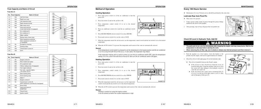
- Specifications, page 146: Fuse Capacity and Name of Circuit
- Controls and operation, page 242: Method of Operation
- Maintenance, page 320: MAINTENANCE
Other manuals for this machine
Save 10% on 2 manuals, 15% on 3 or more. Other manuals for the WA480-6 are listed below. Editions cover different serial number ranges: check the serial coverage and tick only the ones that match your machine.
Added to your cart. View cart
This is an operator's manual
Here's how it compares to the other manual types.
Service manual
Factory repair procedures and technical information such as specifications, troubleshooting, and wiring and hydraulic diagrams, for the models and systems the manual covers. See What's inside for its topics.
Operator's manual
Safe operation, controls, maintenance schedules, lubrication points, inspections, and basic checks. Repair procedures are in the service manual.
Parts manual
Illustrated diagrams with factory part numbers for identifying components and ordering parts. Repair procedures are in the service manual.
What it's used for
Factory manual for in-house farm and construction shop use. Straightforward, complete, and easy to follow. It contains the OEM information dealership service departments and parts counters use to diagnose problems, identify components, and perform maintenance or repairs correctly.
Service shops and owner/operators who repair their own equipment
Identifying correct parts and seeing how assemblies come apart and go back together
Keeping equipment running with less downtime
Factory manual, 429 pages
Quantity one is the manual described above.
Fast free USA shipping
Ships in 1 business day.
60-day returns
Free if the mistake is ours. A manual ordered in error must come back unopened in its shrink-wrap; you pay return shipping and a 20% restocking fee applies. Return policy
Binder not included
Manuals over about 300 pages may need a standard 3-ring binder, which you can buy locally to keep the pages organized for shop use.
Other editions and similar models
Questions about model, serial number, engine coverage or contents? Contact us before purchasing and we'll help confirm it's the right manual. Please verify the manual type, machine model, serial number range and engine coverage before purchasing: manuals ordered in error carry a 20% restocking fee (return policy).