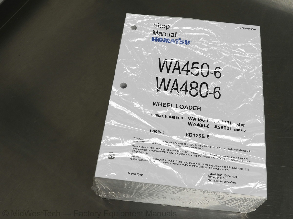
Komatsu WA450-6, WA480-6 with 6D125E-5 Engine Wheel Loader Service Manual
1,624 pages · Publication CEBM018601
Added to your cart. View cart
- Models
- WA450-6, WA480-6 with 6D125E-5 Engine
- Serial coverage
- WA450-6 A44001 and up, WA480-6 A38001 and up
- Manual type
- Service Manual
- Pages
- 1,624
- Publication
- CEBM018601
- Condition
- Brand new
What's inside
From the manual's own table of contents: 6 sections, 545 entries. See sample pages (PDF, 712 KB)
FOREWORD5 topics
- GENERAL
- STRUCTURE, FUNCTION AND MAINTENANCE STANDARD
- TESTING, ADJUSTING AND TROUBLESHOOTING
- DISASSEMBLY AND ASSEMBLY
- DIAGRAMS AND SCHEMATICS
STRUCTURE, FUNCTION AND214 topics
- Lockup Clutch Engaged
- Oil Flow
- Transmission
- Outline
- Transmission with Lockup Clutch
- F and R Clutch Packs
- Without Lockup Clutch
- With Lockup Clutch
- 1st and 4th Clutch
- 2nd and 3rd Clutch
- Operation of Clutch Pack
- When Clutch is Engaged
- When Clutch is Disengaged
- Transmission Torque Flow Route
- Forward 1st Gear Speed
- Forward 2nd Gear Speed
- Forward 3rd Gear Speed
- Forward 4th Gear Speed
- Reverse 1st Gear Speed
- Flow Control Valve
- Operation
- Valve Assembly
- ECMV Operation Table
- Electronic Control Modulation Valve (ECMV)
- ECMV for Gear Speed Clutch
- ECMV for Lockup Clutch
- Main and Torque Converter Relief Valve System
- DRIVE AXLE SYSTEM
- Front and Rear Axles
- Front Axle (WA450-6)
- Front Axle (WA480-6)
- Rear Axle (WA450-6
- Differential
- Front Differential
- Rear Differential
- When Traveling in a Straight Line
- When Turning
- Limited Slip Differential (if equipped)
- Axle Carrier
- WA450-6 and WA480-6 Front Carrier
- Limited Slip Differential Operation
- Generation of Braking Torque by Right / Left Side Gears (5)
- When Machine is Turning
- Final Drives
- STEERING SYSTEM
- Steering Piping Diagram
- Steering Column
- Steering Pump
- Type: LPV90
- Pump Unit
- Servo Valve
- LS Valve
- PC Valve
- Steering Valve
- Operation of Flow Amplifier
- Operation of Flow Control Spool
- Operation of Steering Valve
- Orbit-roll Valve
- Structure
- Connection of Hand Pump and Sleeve
- Role of Centering Spring
- Stop Valve
- Steering Relief Valve (if equipped)
- Steering Cylinder
- Emergency Steering Motor (if equipped)
- Function
- Emergency Steering Pump (if equipped)
- SERVICE BRAKING SYSTEM
- Brake Piping Diagram
- Charge Valve
- Main Relief Valve (R1)
- PPC Relief Valve (R3)
- Sequence Valve (H1)
- Shuttle Valve (S1)
- Brake Valve
- Accumulator for Brake
- Between Charge Valve and Brake Valve
- Between Brake Valve and Brake Cylinder
- Slack Adjuster
- Brakes
- Front Brake
- Rear Brake
- Parking Brake System
- Brake Control
- Parking Brake
- Parking Brake Solenoid Valve
- Emergency Parking Brake Release Valve
- UNDERCARRIAGE AND FRAME
- Axle Mounting and Center Hinge Pin
- Tires
- Tire Structure and Characteristic Comparisons
- HYDRAULIC SYSTEM
- Piping Diagram
- Work Equipment Control Lever System
- Hydraulic Tank
- Tank Vent System
- Specifications
- Power Train Pump
- Work Equipment Pump
- Type: HPV95
- Pump Control Valve System
- PC-EPC Valve
- Work Equipment Control Valve
- Sectional View of Valve (1 of 6)
- Sectional View of Valve (2 of 6)
- Sectional View of Valve (3 of 6)
- Sectional View of Valve (4 of 6)
- Sectional View of Valve (5 of 6)
- Sectional View of Valve (6 of 6)
- CLSS
- Outline of CLSS
- Basic Principle
- Pressure Compensation Control
- Function and Operation of Each Valve
- Main Hydraulic Circuit Diagram of Valves
- Pressure Compensation Valve
- When a Heavy Load is Applied to the Lift Arm
- During Compound Operation (Lift Arm Lower and Bucket Tilt)
- Shuttle Valve in the Pressure Compensation Valve
- Area Ratio of Pressure Compensation Valve
- Supply of LS Pressure
- LS Shuttle Valve
- LS Bypass Plug
- ECSS Control Valve
- Accumulator Pressure Relief Valve
- Restriction on Lift Arm Raise Stroke
- Accumulator Charge Valve
- When Valve is in Neutral and (P) is Low
- When Load Pressure (P) is High
- PPC Valve
- Work Equipment PPC Valve
- Operation in Neutral
- Operations During Fine Control
- At Full Stroke
- When Lift Arm is “Float
- When “Float” State of Lift Arm is Reset
- Accumulator for PPC Circuit
- Accumulator for ECSS
- WORK EQUIPMENT
- Work Equipment Linkage
- Bucket
- Bucket Positioner and Boom Kick-out
- Bucket Positioner
- Boom Kick-out
- Proximity Switch
- When Bucket is Tilted
- When Lift Arm is Raised
- Work Equipment Cylinders
- Lift Cylinder
- Bucket Cylinder
- CAB ENVIRONMENT
- Air Conditioner
- Air Conditioner Piping Diagram
- Refrigerant Circuit Diagram
- Air Conditioner Unit
- Blower and Intake Unit
- Refrigerant Compressor
- Condenser
- Receiver
- Air Conditioner Panel
- ELECTRICAL SYSTEM
- Machine Monitor System
- Operator Mode
- Service Mode
- System Circuit Diagram
- Monitor Display Functions
- List of Items Displayed on Monitor
- Monitor Operational Switches
- Setting the Machine Monitor System
- Character Display Function
- Operator Mode Function
- Service Mode Functions
- Input and Output Signals
- Transmission Controller System
- Gear Shifting Control
- Transmission Controller Protection
- Engine Control Function
- Economy Operation Pilot Lamp Function
- Cooling Fan Control Function
- Fan Reverse Rotation Function
- Work Equipment Swash Plate Control
- Transmission Cut-off
- ECSS Function
- Electric Emergency Steering (if equipped)
- Transmission Controller
- Electronic Transmission Control
- Combination Switch
- Kickdown and Hold Switch
- KOMTRAX Terminal System
- KOMTRAX Terminal
- Engine Starting Circuit
- Engine Stopping Circuit
- Preheating Circuit
- Engine Power Mode Selector Circuit
- Engine Output Derating
- Automatic Warm-up
- Parking Brake Circuit
- When Starting Switch is Turned OFF
- When Starting Switch is Turned ON
- SENSORS
- Speed Sensor
- Torque Converter Oil Temperature Sensor
- Hydraulic Oil Temperature Sensor
- Transmission Oil Temperature Sensor
- Brake Oil Temperature Sensor
- Work Equipment Pump Oil Pressure Sensor
- Steering Pump Oil Pressure Sensor
- Transmission Cut-off Oil Pressure Sensor
- Coolant Level Sensor
- Fuel Level Sensor
- Air Cleaner Clogging Sensor
- Accelerator Pedal Sensor
- Boom Kick-out Proximity Switch
- Bucket Positioner Proximity Switch
TESTING AND ADJUSTING44 topics
- Measuring Parking Brake Pressure
- Transmission Hydraulic Pressure Adjustments
- Adjusting Transmission Main Relief Valve
- Flushing Transmission System
- Torque Converter, Transmission and Hydraulic Circuit
- If Transmission Valve Fails
- Moving Machine
- Special Tools Required
- Check Axle Drive for Oil Leakage
- Check Drive Shafts for Looseness, Play and Damage
- Steering Stop Valve
- Testing
- Adjusting
- Steering Wheel
- Measuring Play in Steering Wheel
- Measuring Operating Effort of Steering Wheel
- Measuring Operating Time of Steering Wheel
- Steering Oil Pressure
- Measuring
- Steering Relief Pressure
- Steering Pilot Circuit Pressure
- Adjusting Steering Control Circuit Pressure
- Bleeding Air from Steering Circuit
- Bleeding Air from Steering Pump
- Bleeding Air from Steering Cylinder Circuit
- HYDRAULIC DRIVE FAN
- Measuring Fan Speed
- Tachometer Kit P1
- Measuring Fan Drive Oil Pressure
- Bleeding Air From Fan Circuit
- Bleeding Air from Fan Pump
- Bleeding Air from Fan Motor Circuit
- WHEEL BRAKE SYSTEM
- Measuring Brake Pedal
- Measuring Pressing Angle of Pedal
- Brake Pedal Linkage
- Brake Performance
- Accumulator Charge
- Accumulator Charge Cut-out Pressure
- Wheel Brake Oil Pressure
- Brake Test Kit
- Wheel Brake Disc Wear
- Bleeding Air from Brake Circuit
- Releasing Residual Pressure in Brake Accumulator Circuit
TROUBLESHOOTING233 topics
- CA123 Charge Pressure Sensor Failure
- CA131 Throttle Sensor High Failure
- CA132 Throttle Sensor Low Failure
- CA135 Engine Oil Pressure Sensor High Error
- CA141 Engine Oil Pressure Sensor High Error
- CA144 Coolant Sensor High Failure
- CA145 Coolant Sensor Low Failure
- CA153 Charge Temperature Sensor High Failure
- CA154 Charge Temperature Sensor Low Failure
- CA187 Sensor Power Supply 2 Low Error
- CA221 Atmospheric Pressure Sensor High Failure
- CA222 Atmospheric Pressure Sensor Low Failure
- CA227 Sensor Power Supply 2 High Failure
- CA234 Engine Overspeed Detected
- CA238 Ne Speed Sensor Power Supply Error
- CA263 Fuel Temperature Sensor High Failure
- CA265 Fuel Temperature Sensor Low Failure
- CA271 PCV1 Short Circuit Detected
- CA272 PCV1 Open Circuit Detected
- CA273 PCV2 Short Circuit Detected
- CA274 PCV2 Open Circuit Detected
- CA322 Injector #1 (L/B#1) Has an Open/Short
- CA323 Injector #5 (L/B#5) Has an Open/Short
- CA324 Injector #3 (L/B#3) Has an Open/Short
- CA325 Injector #6 (L/B#6) Has an Open/Short
- CA331 Injector #2 (L/B#2) Has an Open/Short
- CA332 Injector #4 (L/B#4) Has an Open/Short
- CA342 Calibration Code Inconsistency
- CA351 Injectors Drive Circuit Error
- CA352 Sensor Power Supply 1 Low Failure
- CA386 Sensor Power Supply 1 High Failure
- CA431 Idle Validation Switch Error
- CA432 Idle Validation Switch Action Error
- CA435 Engine Oil Pressure Switch Error
- CA441 Low Battery Voltage Error
- CA442 High Battery Voltage Error
- CA449 Common Rail Pressure High Error 2
- CA451 Common Rail Pressure Sensor High Error
- CA452 Common Rail Pressure Sensor Low Error
- CA488 Derating of Torque by Abnormally High Charge Temperatures
- CA553 Common Rail Pressure High Error 1
- CA554 Common Rail Pressure Sensor In-range Error
- CA559 Supply Pump Pressure Very Low Error
- Check Sheet For No-pressure Feed
- WA450-6 Specifications
- WA480-6 Specifications
- CA689 Ne Speed Sensor Error
- CA731 Engine Bkup Speed Sensor Phase Error
- CA757 All Continuous Data Loss Error
- CA778 Engine Bkup Speed Sensor Error
- CA1228 EGR Valve Servo Error 1
- CA1625 EGR Valve Servo Error 2
- CA1633 KOMNET Data Link Time Out Error
- CA2185 Throttle Sensor Supply Voltage High Failure
- CA2186 Throttle Sensor Supply Voltage Low Failure
- CA2249 Supply Pump Pressure Very Low Error
- CA2271 EGR Valve Lift Sensor High Error
- CA2272 EGR Valve Lift Sensor Low Error
- CA2351 EGR Valve Solenoid Showing Short Circuit Error
- CA2352 EGR Valve Solenoid Showing Open Circuit Error
- CA2311 PCV1 Short or Open Circuit Detected
- CA2555 Intake Heater Relay Open Error
- CA2556 Intake Heater Relay Short Error
- D150KA Emergency Steering Relay Open
- D150KB Emergency Steering Relay Shorted
- D150KY Emergency Steering Relay Shorted with Power Supply
- D160KA Backup Lamp Relay Open
- D160KB Backup Lamp Relay Shorted
- D191KY Joystick Steering Neutral Safety Relay Open
- D191KB Joystick Steering Neutral Safety Relay Shorted
- D191KY Joystick Steering Neutral Safety Relay Shorted
- D192KA ECSS Solenoid Open
- D192KB ECSS Solenoid Shorted
- D192KY ECSS Solenoid Power Supply Error
- D193KA Joystick Steering Solenoid Cut Relay Shorted
- D193KB Joystick Steering Solenoid Cut Relay Shorted
- D193KY Joystick Steering Solenoid Cut Relay Shorted
- D5ZHKA Terminal C Signal Open
- D5ZHKB Terminal C Signal Shorted
- D5ZHL6 Terminal C Signal Does Not Match Engine Running or Stopped
- DA80L4 Auto Grease Controller On/Off Signals Disagree
- DAF3KK Machine Monitor Low Voltage Input
- DAF5KP Machine Monitor Low Output Voltage
- DAFRKR CAN Communication with Machine Monitor Defective
- DAQ0KK Transmission Controller Low Voltage Source
- DAQ0KT Transmission Controller Defective
- DAQ2KK Transmission Controller Low Voltage Source Input
- DAQ9KQ Transmission Controller Model Selection Disagreement
- DAQRKR CAN Communication with Transmission Controller Abnormal
- DAQRMA Transmission Controller Option Setting Malfunction
- DB2RKR CAN Communication with Engine Controller Abnormal
- DB90KK Work Equipment Controller Low Voltage Source
- DB90KT Work Equipment Controller Malfunction
- DB92KK Work Equipment Controller Low Voltage Input Source
- DB95KX Work Equipment Power Supply Output, Out of Range
- DB99KQ Work Equipment Controller Model Selection Disagreement
- DB9RKR CAN Communication with Work Equipment Controller Abnormal
- DB9RMA Work Equipment Controller Option Setting Malfunction
- DB9RMC Communication with Transmission Controller Defective
- DD15LD n Switch (Panel Switch 1) is Defective
- DD16LD u Switch (Panel Switch 2) is Defective
- DD17LD < Switch (Panel Switch 3) is Defective
- DD18LD > Switch (Panel Switch 4) is Defective
- DD1ALD Remote Positioner Set Switch is Defective
- DD1BLD Remote Positioner Set Switch is Defective
- DD1CLD Load Meter Subtotal Switch Defective
- DD1FLD Load Meter Mode Selector Switch (A/B) is Defective
- DD1GLD Load Meter Mode Selector Switch (+/-) is Defective
- DD1HLD Load Meter Display Selector Switch is Defective
- DD1NLD Fan Reverse Selector Switch is Defective
- DD1NL4 Fan Reverse Selector Switch is Defective
- DDB6L4 Parking Brake Switch On/Off Signals Disagree
- DDD1LD Remote Bucket Positioner Switch is Defective
- DDE5MA Emergency Steering Drive Switch Malfunction
- DDK3KA Right FNR Switch Showing Open
- DDK4KA FNR Switch Showing Open
- DDK5L4 Joystick Steering Shift-up Switch On/Off Signal Error
- DDK6KA FNR Switch Showing Open
- DDK6KB FNR Switch Showing a Short
- DDT0L4 Shift Mode Selector Switch On/Off Signals Incorrect
- DDT4LD Transmission Cut-off Switch is Defective
- DDW9LD Kick-down Switch Defective
- DDWLLD Hold Switch Defective
- DDY0LD Load Meter Cancel Switch Defective
- DF10KA Transmission Shift Lever Switch Open
- DF10KB Transmission Shift Lever Switch Shorted
- DGF1KA Transmission Oil Temperature Sensor Showing Open
- DGF1KB Transmission Oil Temperature Sensor Showing a Short
- DGH2KX Hydraulic Oil Temperature Sensor Out of Range
- DGR2KA Rear Brake Oil Temperature Sensor Open
- DGR2KX Rear Brake Oil Temperature Sensor Shorted
- DGT1KX Torque Converter Oil Temperature Sensor Out of Range
- DHPCKX Lift Arm Cylinder Bottom Pressure Sensor Out of Range
- DHPDKX Lift Arm Cylinder Head Pressure Sensor Out of Range
- DHT1KX Transmission Cut-off Pressure Sensor Out of Range
- DHT8KA Steering Pump Pressure Sensor Open
- DHT8KB Steering Pump Pressure Sensor Short Circuit
- DK59KA Lift Arm Epc Lever Showing Open
- DK59KY Lift Arm EPC Lever Showing a Short
- DK59L8 Lift Arm EPC Lever Showing Incorrect Signals
- DK5AKA Lift Arm Epc Lever Showing Open
- DK5AKY Lift Arm EPC Lever Shorted
- DK5BKA Bucket EPC Lever Showing Open
- DK5BKY Bucket EPC Lever System Shorted
- DK5BL8 Bucket EPC Lever Showing Incorrect Signals
- DK5CKA Bucket EPC Lever System Open
- DK5CKY Bucket EPC Lever System Shorted
- DK5DKA 3-Spool Attachment EPC Lever System Showing Open
- DK5DKY 3-Spool Attachment EPC Lever System Showing a Short
- DK5DL8 3-Spool EPC Lever Showing Incorrect Signals
- DK5EKA 3-Spool Attachment EPC Lever System Showing Open
- DK5EKY 3-Spool Attachment EPC Lever System Showing Short
- DK5FKA Joystick Steering EPC Lever System Showing Open
- DK5FKY Joystick Steering EPC Lever System Showing a Short
- DK5GKA Joystick Steering EPC Lever System Showing an Open
- DK5GKY Joystick Steering EPC Lever System Showing a Short
- DK5FL8 Joystick Steering EPC Lever System Incorrect Signals
- DKA0KA Lift Arm Angle Sensor System Showing an Open
- DKA0KY Lift Arm Angle Sensor System Showing a Short
- DKA0L0 Lift Arm Angle Sensor System Double Meshing
- DLT3KA Transmission Speed Sensor Open
- DLT3LC Transmission Speed Sensor Out of Range
- DT20KB Transmission Cut-off Indicator Lamp Shorted
- DUM1KB Remote Positioner Raise Set Indicator Shorted
- DUM2KB Remote Positioner Raise Set Indicator Shorted
- DV00KB Alarm Buzzer Shorted
- DW4PKA Lift Arm Raise EPC Solenoid Showing Open
- DW4PKB Lift Arm Raise EPC Solenoid Showing a Short Circuit
- DW4PKY Lift Arm Raise EPC Solenoid Showing a Short Circuit
- DW4QKA Lift Arm Lower EPC Solenoid Showing an Open
- DW4QKB Lift Arm Lower EPC Solenoid Showing a Short
- DW4RKA Bucket Tilt EPC Solenoid Showing an Open
- DW4RKB Bucket Tilt EPC Solenoid Showing a Short
- DW4SKA Bucket Dump EPC Solenoid Showing an Open
- DW4SKB Bucket Dump EPC Solenoid Showing a Short
- DW4SKY Bucket Dump EPC Solenoid Showing a Short
- DW7BKA Fan Reverse Solenoid Open
- DW7BKB Fan Reverse Solenoid Shorted
- DW7BKY Fan Reverse Solenoid Shorted
- DW7DKA Hydraulic Fan Neutral Solenoid Showing Open
- DW7DKB Hydraulic Fan Neutral Solenoid Shorted
- DW7DKY Hydraulic Fan Neutral Solenoid Showing Open
- DWM1KA Work Equipment Neutral Lock Solenoid Showing Open
- DWM1KB Work Equipment Neutral Lock Solenoid Shorted
- DWM1KY Work Equipment Neutral Lock Solenoid Shorted
- DWN6KA Lift Arm Raise Magnetic Detent Solenoid Showing Open
- DWN6KB Lift Arm Raise Magnetic Detent Solenoid is Shorted
- DWN6KY Lift Arm Raise Magnetic Detent Solenoid is Shorted
- DWN7KA Lift Arm Float Magnetic Detent Solenoid Showing Open
- DWN7KB Lift Arm Float Magnetic Detent Solenoid Showing Short
- DWN7KY Lift Arm Float Magnetic Detent Solenoid Showing Short
- DWN8KA Bucket Magnetic Detent Solenoid Showing Open
- DWN8KB Bucket Magnetic Detent Solenoid Shorted
- DWN8KY Bucket Magnetic Detent Solenoid Shorted
- DX16KA Fan Pump EPC Solenoid Open
- DX16KB Fan Pump EPC Solenoid Shorted
- DX16KY Fan Pump EPC Solenoid Shorted
- DXH1KA Lock-up ECMV Solenoid Open
- DXH1KB Lock-up ECMV Solenoid Shorted
- DXH1KY Lock-up ECMV Solenoid Shorted
- DXH4KA 1st Clutch ECMV Solenoid Open
- DXH4KB 1st Clutch ECMV Solenoid Shorted
- DXH4KY 1st Clutch ECMV Solenoid Shorted
- DXH5KA 2nd Clutch ECMV Solenoid Open
- DXH5KB 2nd Clutch ECMV Solenoid Shorted
- DXH5KY 2nd Clutch ECMV Solenoid Shorted
- DXH6KA 3rd Clutch ECMV Solenoid Open
- DXH6KB 3rd Clutch ECMV Solenoid Shorted
- DXH6KY 3rd Clutch ECMV Solenoid Shorted
- DXH7KA Reverse (R) Clutch ECMV Solenoid Open
- DXH7KB Reverse (R) Clutch ECMV Solenoid Shorted
- DXH7KY Reverse (R) Clutch ECMV Solenoid Shorted
- DXH8KA Forward (F) Clutch ECMV Solenoid Open
- DXH8KB Forward (F) Clutch ECMV Solenoid Shorted
- DXH8KY Forward (F) Clutch ECMV Solenoid Shorted
- DXHHKA 4th Clutch ECMV Solenoid Open
- DXHHKB 4th Clutch ECMV Solenoid Shorted
- DXHHKY 4th Clutch ECMV Solenoid Shorted
- DXHJKA 3-Spool Valve Extend EPC Solenoid Showing an Open
- DXHJKB 3-Spool Valve Extend EPC Solenoid Showing a Short
- DXHJKY 3-Spool Valve Extend EPC Solenoid Showing a Short
- DXHKKA 3-Spool Valve Retract EPC Solenoid Showing an Open
- DXHKKB 3-Spool Valve Extend EPC Solenoid Showing a Short
- DXHKKY 3-Spool Valve Extend EPC Solenoid Showing a Short
- DXHLKA Joystick Steering Right EPC Solenoid Showing Open
- DXHLKB Joystick Steering Right EPC Solenoid Shorted
- DXHLKY Joystick Steering Right EPC Solenoid Shorted
- DXHMKA Joystick Steering Left EPC Solenoid Showing Open
- DXHMKB Joystick Steering Left EPC Solenoid Shorted
- DXHMKY Joystick Steering Left EPC Solenoid Showing Open
- DY30MA Motor-driven Emergency Steering Pump Failure (During Operation of Machine)
- DY30MC Motor-driven Emergency Steering Pump Failure (Malfunction in Manual Mode)
- DY30ME Emergency Steering: Operating for More Than One Minute
DISASSEMBLY AND ASSEMBLY30 topics
- Removal
- Installation
- Fuel Supply Pump
- Special Tools
- Fuel Injector
- Cylinder Head
- Fuel Tank
- POWER TRAIN
- Torque Converter and Transmission
- Torque Converter - Standard Specifications
- Disassembly
- Assembly
- Torque Converter - Lockup Specifications
- Transmission Clutch Pack
- Front Axle
- Rear Axle
- Axle Housing
- Center Hinge Pin
- Counterweight
- Steering Demand Valve
- Work Equipment Valve
- Brake Charge Valve
- Steering and Power Train Pump
- Work Equipment and Cooling Fan Pump
- CAB AND ITS ATTACHMENTS
- Operator's Cab and Floor Frame
- Operator's Cab Glass (Stuck Glass)
- Operator’s Seat
- Engine Controller
- KOMTRAX Controller
OTHERS13 topics
- CONNECTING HARNESS VIEW (VIEW 40 OF 47)
- ENGINE ACCESSORIES (VIEW 41 OF 47)
- ENGINE CONTROL MODULE (VIEW 42 OF 47)
- GROUND DRIVEN STEERING (VIEW 43 OF 47)
- FRONT HARNESS AND LOAD METER (VIEW 44 OF 47)
- ENGINE CONTROL MODULE HARNESS (VIEW 46 OF 47)
- ENGINE FUEL INJECTORS (VIEW 47 OF 47)
- HYDRAULIC CIRCUIT DIAGRAM
- POWER TRAIN HYDRAULIC CIRCUIT DIAGRAM
- CONNECTOR LIST AND STEREOGRAM
- CHASSIS (VIEW 1 OF 3)
- ENGINE AND TRANSMISSION (VIEW 2 OF 3)
- OPERATOR’S COMPARTMENT (VIEW 3 OF 3)
Inside this manual
Real pages from this service manual (1,624 pages). Open the sample pages (PDF, 711 KB)
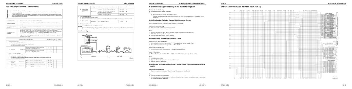
- Specifications, page 667: Tools and Procedures
- Diagram, page 1,067: Related circuit diagram
- Troubleshooting, page 1,292: TROUBLESHOOTING
- Foldout diagram, page 1,580: OTHERS
Other manuals for this machine
Save 10% on 2 manuals, 15% on 3 or more. Other manuals for the WA450-6 are listed below. Editions cover different serial number ranges: check the serial coverage and tick only the ones that match your machine.
Added to your cart. View cart
This is a service manual
Here's how it compares to the other manual types.
Service manual
Factory repair procedures and technical information such as specifications, troubleshooting, and wiring and hydraulic diagrams, for the models and systems the manual covers. See What's inside for its topics.
Operator's manual
Safe operation, controls, maintenance schedules, lubrication points, inspections, and basic checks. Repair procedures are in the service manual.
Parts manual
Illustrated diagrams with factory part numbers for identifying components and ordering parts. Repair procedures are in the service manual.
Engine service manuals are sometimes sold separately, since certain machine models were offered with more than one engine option.
What it's used for
Factory manual for in-house farm and construction shop use. Straightforward, complete, and easy to follow. It contains the OEM information dealership service departments and parts counters use to diagnose problems, identify components, and perform maintenance or repairs correctly.
Service shops and owner/operators who repair their own equipment
Identifying correct parts and seeing how assemblies come apart and go back together
Keeping equipment running with less downtime
Factory manual, 1,624 pages
Quantity one is the manual described above.
Fast free USA shipping
Ships in 1 business day.
60-day returns
Free if the mistake is ours. A manual ordered in error must come back unopened in its shrink-wrap; you pay return shipping and a 20% restocking fee applies. Return policy
Binder not included
Manuals over about 300 pages may need a standard 3-ring binder, which you can buy locally to keep the pages organized for shop use.
Other editions and similar models
Questions about model, serial number, engine coverage or contents? Contact us before purchasing and we'll help confirm it's the right manual. Please verify the manual type, machine model, serial number range and engine coverage before purchasing: manuals ordered in error carry a 20% restocking fee (return policy).