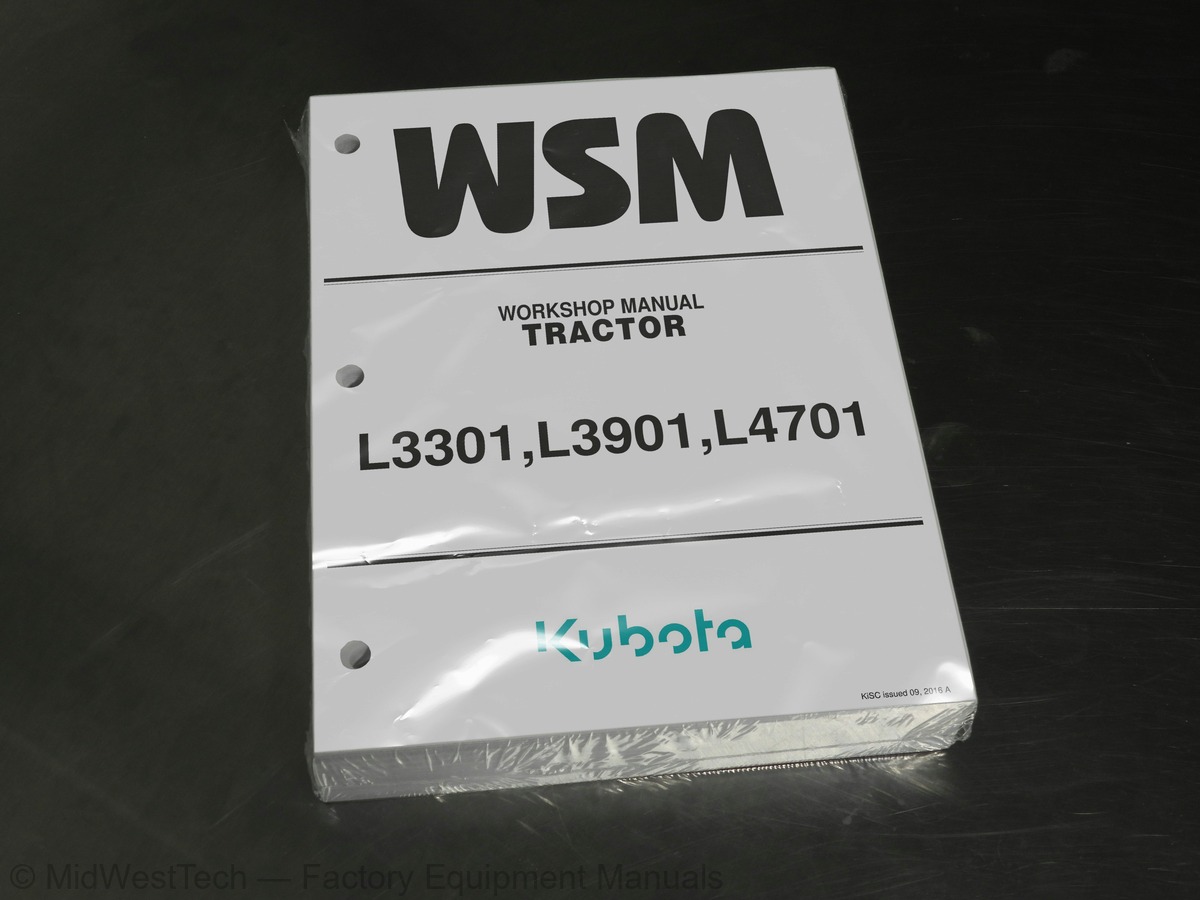
Kubota L3301, L3901, L4701 Tractor Service Manual
662 pages · Publication 9Y111-10121
Added to your cart. View cart
What's inside
From the manual's own table of contents: 132 sections, 255 entries. See sample pages (PDF, 663 KB)
TRACTOR IDENTIFICATION3 topics
- MODEL NAME AND SERIAL NUMBERS
- E4B ENGINE
- CYLINDER NUMBER
HANDLING PRECAUTIONS FOR ELECTRICAL PARTS AND WIRING6 topics
- WIRING
- BATTERY
- FUSE
- CONNECTOR
- CIRCUIT TESTER
- COLOR OF WIRING
TIGHTENING TORQUES3 topics
- GENERAL USE SCREWS, BOLTS AND NUTS
- STUD BOLTS
- METRIC SCREWS, BOLTS AND NUTS
THREADS1 topic
- PLUGS
Show all 132 sections
ENGINE BODY2 topics
- PISTON
- HALF-FLOATING HEAD COVER
LUBRICATING SYSTEM1 topic
- OIL COOLER
COOLING SYSTEM2 topics
- THERMOSTAT
- BOTTOM BYPASS SYSTEM
FUEL SYSTEM5 topics
- OVERVIEW OF COMMON RAIL SYSTEM
- SUPPLY PUMP
- RAIL
- INJECTOR
- ENGINE CONTROL SYSTEM
EGR SYSTEM3 topics
- OVERVIEW
- EGR COOLER
- EGR VALVE
AFTER TREATMENT SYSTEM1 topic
- AFTER TREATMENT DEVICES
CHECKING AND ADJUSTING6 topics
- ENGINE BODY
- LUBRICATING SYSTEM
- COOLING SYSTEM
- PCV VALVE
- EGR COOLER
- ACCELERATION SENSOR
PREPARATION3 topics
- SEPARATING DPF MUFFLER FROM TRACTOR
- SEPARATING ENGINE FROM CLUTCH HOUSING
- SEPARATING ENGINE FROM FRONT AXLE FRAME
DISASSEMBLING AND ASSEMBLING9 topics
- OUTER PARTS
- COMMON RAIL
- CYLINDER HEAD AND VALVES
- THERMOSTAT
- SUPPLY PUMP
- WATER PUMP AND OIL COOLER
- GEAR CASE AND TIMING GEAR
- PISTON AND CONNECTING ROD
- FLYWHEEL AND CRANKSHAFT
SERVICING6 topics
- CYLINDER HEAD AND VALVES
- TIMING GEARS
- PISTON AND CONNECTING ROD
- CRANKSHAFT
- CYLINDER
- OIL PUMP
FEATURE1 topic
- TRAVELING CLUTCH
(2) Separating Clutch Assembly2 topics
- SINGLE STAGE CLUTCH
- DUAL STAGE CLUTCH
STRUCTURE2 topics
- MANUAL TRANSMISSION MODEL
- HYDROSTATIC TRANSMISSION (HST) MODEL
MANUAL TRANSMISSION MODEL1 topic
- POWER TRAIN FOR TRAVELING GEARS
(4) Front Wheel Drive Section (4WD Model Only)1 topic
- PTO SYSTEM
HYDROSTATIC TRANSMISSION (HST) MODEL1 topic
- Hydrostatic Transmission Assembly
(3) Operation1 topic
- POWER TRAIN FOR TRAVELING GEARS
(2) Front Wheel Drive Section1 topic
- LINKAGE MECHANISM
(2) Cruise Control1 topic
- PTO SYSTEM
(3) Transmission Case4 topics
- SEPARATING REAR AXLE CASE
- DISASSEMBLING REAR AXLE
- SEPARATING BRAKE CASE
- DISASSEMBLING THE BRAKE CASE
(2) Disassembling Front Axle6 topics
- 2WD MODEL
- 4WD MODEL
- LINKAGE
- HYDRAULIC CIRCUIT
- HYDRAULIC PUMP
- STEERING GEAR BOX
STRUCTURE (L4701)4 topics
- LINKAGE
- HYDRAULIC CIRCUIT
- HYDRAULIC PUMP
- STEERING CONTROLLER
(3) Oil Flow5 topics
- STEERING CYLINDER
- STEERING WHEEL PLAY (L3301/L3901)
- HYDRAULIC PUMP TEST USING FLOW-METER (POWER STEERING)
- RELIEF VALVE
- BLEEDING
THREE POINT HITCH HYDRAULIC SYSTEM6 topics
- THREE POINT HITCH HYDRAULIC CIRCUIT
- HYDRAULIC CYLINDER
- LINKAGE MECHANISM
- POSITION CONTROL VALVE
- HYDRAULIC PUMP
- SAFETY VALVE
FRONT HYDRAULIC BLOCK4 topics
- STRUCTURE
- HYDRAULIC CIRCUIT
- RELIEF VALVE
- HYDRAULIC PUMP (POWER STEERING)
(1) Test Using Flow-meter2 topics
- HYDRAULIC PUMP (THREE POINT HITCH HYDRAULIC SYSTEM)
- RELIEF VALVE
(2) Power Steering System8 topics
- SAFETY VALVE
- POSITION CONTROL ROD
- HYDRAULIC PUMP
- HYDRAULIC CYLINDER
- POSITION CONTROL VALVE
- RELIEF VALVE
- HYDRAULIC PUMP
- HYDRAULIC CYLINDER
INSTRUMENT PANEL2 topics
- SYSTEM OUTLINE
- CONSTRUCTION AND FUNCTION OF COMPONENTS
(5) Others1 topic
- BASIC CONTROL SYSTEM
(2) Easy Checker™1 topic
- ASSISTANT CONTROL SYSTEM
ENGINE STARTING SYSTEM AND STOPPING4 topics
- STARTING CIRCUIT
- RELATED PARTS
- ENGINE STARTING CONDITIONS
- OPERATOR PRESENCE CONTROL (OPC)
CAN (CONTROLLER AREA NETWORK)2 topics
- BATTERY
- TESTING, SETTING AND ADJUSTING BY ELECTRONIC INSTRUMENT PANEL
(5) Mode "d" (Tractor Model Select Mode)1 topic
- FUSES AND GROUND CABLE
(1) Checking Fuse and Connector1 topic
- ELECTRONIC INSTRUMENT PANEL
(1) Checking Electronic Instrument Panel Connector1 topic
- MAIN ELECTRIC CONTROL UNIT (MAIN ECU)
(1) Checking Main Electrical Control Unit Connector1 topic
- ENGINE ELECTRIC CONTROL UNIT (ENGINE ECU)
(1) Checking Electric Control Unit Connector1 topic
- STARTING SYSTEM
(5) Glow Control System1 topic
- OPC (OPERATOR PRESENCE CONTROL) SYSTEM
(3) Safety Switch2 topics
- CHARGING SYSTEM
- LIGHTING SYSTEM
(2) Flasher Unit4 topics
- WARNING LAMP
- MONITOR LAMP
- GAUGES
- ENGINE CONTROL SYSTEM
Inside this manual
Real pages from this service manual (662 pages). Open the sample pages (PDF, 662 KB)

- Troubleshooting, page 249: CLUTCH
- Specifications, page 449: BRAKES
- Diagram, page 549: HYDRAULIC SYSTEM
- Color page, page 200: ENGINE
- Color page, page 594: ELECTRICAL SYSTEM
- Foldout diagram, page 581: ELECTRICAL SYSTEM
This is a service manual
Here's how it compares to the other manual types.
Service manual
Factory repair procedures and technical information such as specifications, troubleshooting, and wiring and hydraulic diagrams, for the models and systems the manual covers. See What's inside for its topics.
Operator's manual
Safe operation, controls, maintenance schedules, lubrication points, inspections, and basic checks. Repair procedures are in the service manual.
Parts manual
Illustrated diagrams with factory part numbers for identifying components and ordering parts. Repair procedures are in the service manual.
Engine service manuals are sometimes sold separately, since certain machine models were offered with more than one engine option.
What it's used for
Factory manual for in-house farm and construction shop use. Straightforward, complete, and easy to follow. It contains the OEM information dealership service departments and parts counters use to diagnose problems, identify components, and perform maintenance or repairs correctly.
Service shops and owner/operators who repair their own equipment
Identifying correct parts and seeing how assemblies come apart and go back together
Keeping equipment running with less downtime
Factory manual, 662 pages
Quantity one is the manual described above.
Fast free USA shipping
Ships in 1 business day.
60-day returns
Free if the mistake is ours. A manual ordered in error must come back unopened in its shrink-wrap; you pay return shipping and a 20% restocking fee applies. Return policy
Binder not included
Manuals over about 300 pages may need a standard 3-ring binder, which you can buy locally to keep the pages organized for shop use.
Other editions and similar models
Questions about model, serial number, engine coverage or contents? Contact us before purchasing and we'll help confirm it's the right manual. Please verify the manual type, machine model, serial number range and engine coverage before purchasing: manuals ordered in error carry a 20% restocking fee (return policy).