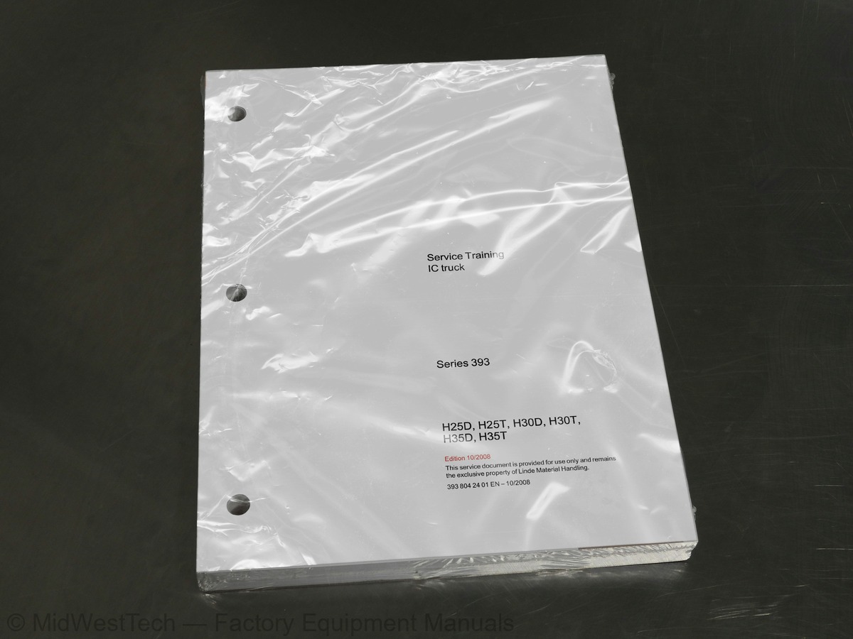
Linde H25D, H25T, H30D, H30T, H35D, H35T IC Forklift Service Manual
442 pages · Publication 393-804-2401
Added to your cart. View cart
- Models
- H25D, H25T, H30D, H30T, H35D, H35T IC
- Manual type
- Service Manual
- Pages
- 442
- Publication
- 393-804-2401
- Condition
- Brand new
What's inside
From the manual's own table of contents: 100 sections, 198 entries. See sample pages (PDF, 513 KB)
General15 topics
- Foreword
- The truck
- Diagnostics
- LTC basic structure
- LPG engine
- Description of the drive
- Engine block
- Cooling
- Engine electrics
- LPG system
- Safety guidelines for LPG (extract)
- Basic rules when working with LPG
- Sealing plastic pipe unions
- Functions
- LPG system with lambda control system
Fuel supply33 topics
- Engine block
- Checking hydraulic bucket tappets
- Camshaft - removal and installation
- Vacuum pump
- Air volumeter 0B6
- Solenoid valve for charge pressure limitation 0Y4
- Turbocharging system exhaust turbocharger
- Exhaust gas recirculation - removal and installation
- Exhaust gas recirculation - check
- Cooling
- Coolant −draining and filling
- Coolant thermostat - removal and installation
- Water pump - removal and installation
- Coolant pump −Checking for wear
- Engine electrics
- Three-phase alternator
- Replacing the engine control unit / immobilizer
- Self-diagnostics
- Self-test - introduction
- Self-diagnostics −troubleshooting
- Standardised measured value blocks
- Measured value block 01 −evaluation
- Measured value block 03 −evaluation
- Measured value block 04 −evaluation
- Measured value block 05 −evaluation
- Measured value block 07 −evaluation
- Measured value block 10 −evaluation
- Measured value block 11 −evaluation
- Measured value block 12 −evaluation
- Measured value block 13 −evaluation
- CBHA diesel engine (pump injection)
- Description of the drive
- CBHA technical data
Show all 101 sections
Exhaust gas recirculation −overview33 topics
- Checking exhaust gas recirculation
- Checking the exhaust gas recirculation valve 0Y3
- Checking the mechanical exhaust gas recirculation valve
- Cooling
- Checking the cooling system for leaks
- Draining and filling coolant
- Removing and installing the coolant thermostat
- Removing and installing the coolant pump
- Self-diagnostics
- Self-diagnostics −introduction
- Error code table
- Standardised measured value blocks
- Measured value block 01 −fuel injection quantity
- Measured value block 03 −exhaust gas recirculation
- Measured value block 04 −pump/nozzle unit activation
- Measured value block 07 −temperatures
- Measured value block 10 −air variables
- Measured value block 11 −charge pressure control
- Measured value block 12 −heating status
- Measured value block 13 −idling smooth running control
- Measured value block 18 −valve status of pump injection units
- Measured value block 23 −BIP deviation (solenoid valve switching times)
- Description
- System overview
- Drive unit
- Start of delivery of the pump
- Bypass valve
- Output unit
- Hydraulic fan drive
- Hydraulic truck diagnostics
- Overview and explanations about diagnostics
- HPV 75 -02 pressures - tests
- Hydrostatic travel drive - check
Testing the indicator unit13 topics
- Working hydraulics
- Pressure relief valve
- Lift mast
- Lift mast - identification
- Installation of mast type 188
- Setting the roller play
- Lift cylinder - sealing
- Setting the tilt angle sensor
- Tilt cylinders
- Hose reservoir −removal, exchanging hose, sealing, fitting
- Hydraulic circuit diagrams
- Hydraulic circuit diagram up to 09/2006
- Traction, working and steering hydraulics
Special equipment wiring diagrams1 topic
- brake light, interior lighting
Special equipment sheet 4 −Hazard warning system for reversing, higher lighting1 topic
- vehicle deactivation, Forklift Data Management
Special equipment sheet 6 −Particulate filter, diesel filter water trap warning2 topics
- and 6, coolant and engine oil level monitoring
- exchangeable particulate filter, rear window heater, camera system
Inside this manual
Real pages from this service manual (442 pages). Open the sample pages (PDF, 512 KB)

- Specifications, page 74: BEU diesel engine
- Troubleshooting, page 146: BEU diesel engine
- Diagram, page 404: Circuit diagrams
- Color page: Hydraulic system
- Color page: Hydraulic system
- Foldout diagram (color): Circuit diagrams
This is a service manual
Here's how it compares to the other manual types.
Service manual
Factory repair procedures and technical information such as specifications, troubleshooting, and wiring and hydraulic diagrams, for the models and systems the manual covers. See What's inside for its topics.
Operator's manual
Safe operation, controls, maintenance schedules, lubrication points, inspections, and basic checks. Repair procedures are in the service manual.
Parts manual
Illustrated diagrams with factory part numbers for identifying components and ordering parts. Repair procedures are in the service manual.
Engine service manuals are sometimes sold separately, since certain machine models were offered with more than one engine option.
What it's used for
Factory manual for in-house farm and construction shop use. Straightforward, complete, and easy to follow. It contains the OEM information dealership service departments and parts counters use to diagnose problems, identify components, and perform maintenance or repairs correctly.
Service shops and owner/operators who repair their own equipment
Identifying correct parts and seeing how assemblies come apart and go back together
Keeping equipment running with less downtime
Factory manual, 442 pages
Quantity one is the manual described above.
Fast free USA shipping
Ships in 1 business day.
60-day returns
Free if the mistake is ours. A manual ordered in error must come back unopened in its shrink-wrap; you pay return shipping and a 20% restocking fee applies. Return policy
Binder not included
Manuals over about 300 pages may need a standard 3-ring binder, which you can buy locally to keep the pages organized for shop use.
Questions about model, serial number, engine coverage or contents? Contact us before purchasing and we'll help confirm it's the right manual. Please verify the manual type, machine model, serial number range and engine coverage before purchasing: manuals ordered in error carry a 20% restocking fee (return policy).