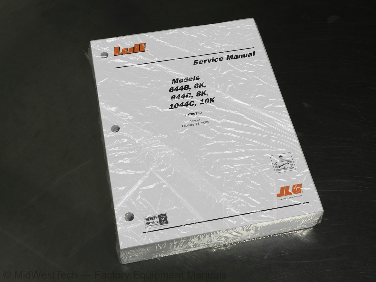
Lull 644B, 6K, 844C, 8K, 1044C, 10K Telehandler Service Manual
636 pages · Publication 10709790
Added to your cart. View cart
What's inside
From the manual's own table of contents: 204 sections, 636 entries. See sample pages (PDF, 436 KB)
Show all 204 sections
Specifications1 topic
- Table of Contents Engine Specifications
Replacing Return Filter Element1 topic
- Table of Contents Reservoir Breather
Troubleshooting1 topic
- Table of Contents Boom Slide Pads — General
Adjustments1 topic
- Table of Contents Transfer Carriage
Rear Oscillation Lock Cylinder1 topic
- Table of Contents Oscillation Control Block
Service Brake Pressure Switch Replacement1 topic
- Table of Contents Accumulator
Outrigger Control Valves426 topics
- Fig. 1-1: Decals and Placards
- Fig. 1-2: Instrument Panel Decals
- Fig. 1-3: Control Decals
- Fig. 1-4: Disconnect Battery Decal and Slow Moving Vehicle Sign
- Fig. 1-5: Steer Selector Plate
- Fig. 1-6: Hydraulic Reservoir/Fuel Tank Decals
- Fig. 1-7: Fork Carriage Decals
- Fig. 2-1: Machine Serial Number Plate
- Fig. 2-2: Stamped Machine Serial Number
- Fig. 2-3: Engine Serial Number — John Deere
- Fig. 2-4: Engine Serial Number — Cummins
- Fig. 2-5: Axle Serial Number
- Fig. 2-6: Attachment Serial Number Plate
- Fig. 3-1: SAE Grade Identification
- Fig. 3-2: Metric Class Identification
- Fig. 5-1: Major Hydraulic Components
- Fig. 5-2: Control Manifold Hydraulic Components
- Fig. 5-3: Mid-Inlet Hydraulic Components
- Fig. 5-4: Hydraulic Reservoir Location
- Fig. 5-5: Hydraulic Reservoir
- Fig. 5-6: Recommended Reservoir Filling Method
- Fig. 5-7: Alternate Reservoir Filling Method
- Fig. 5-8: Hydraulic Reservoir Drain and Refill
- Fig. 5-9: Hydraulic Reservoir/Fuel Tank Installation
- Fig. 5-10: Hydraulic Reservoir Sight Gauge
- Fig. 5-11: Reservoir Sight Gauge Installation
- Fig. 5-12: Suction Strainer Installation
- Fig. 5-13: Hydraulic Return Filter
- Fig. 5-14: Return Filter Pressure Gauge
- Fig. 5-15: Filter Housing Cover
- Fig. 5-16: Filter Element Assembly
- Fig. 5-17: Return Filter Assembly
- Fig. 5-18: Reservoir Breather
- Fig. 5-19: Hydraulic Pressure Filter – Control Manifold Hydraulics
- Fig. 5-20: Pressure Filter Service Indicator
- Fig. 5-21: Hydraulic Pressure Filter Element
- Fig. 5-22: Hydraulic Pressure Filter Assembly
- Fig. 5-23: Hydraulic Pump Location
- Fig. 5-24: Hydraulic Pump Installation – Control Manifold Hydraulics
- Fig. 5-25: Hydraulic Pump Hoses – Mid-Inlet Hydraulics
- Fig. 5-26: Hydraulic Pump Installation – Mid-Inlet Hydraulics
- Fig. 5-27: Checking Hydraulic Pump Flow Rate
- Fig. 5-28: Multi-Spool Control Valve Location
- Fig. 5-29: Control Valve Configurations, Models 644B, 844C, and 1044C
- Fig. 5-30: Control Valve Configurations, Models 6K, 8K, and 10K
- Fig. 5-31: Multi-Spool Control Valve Components
- Fig. 5-32: Multi-Spool Control Valve Installation
- Fig. 5-33: Hydraulic Control Valve Sections
- Fig. 5-34: Spool Assembly
- Fig. 5-35: Load Check Assembly
- Fig. 5-36: CRA Assembly
- Fig. 5-37: Outlet and Inlet Covers
- Fig. 5-38: Power-Beyond Sleeve Assembly
- Fig. 5-39: Main Relief Valve
- Fig. 5-40: Hydraulic Control Manifold Location
- Fig. 5-41: Hydraulic Control Manifold Valves
- Fig. 5-42: Hydraulic Control Manifold Ports
- Fig. 5-43: Hydraulic Control Manifold Removal/Installation
- Fig. 5-44: Hydraulic Control Manifold Block Fittings Removal/Installation
- Fig. 5-45: Hydraulic Control Manifold Assembly
- Fig. 5-46: Pump Unloader Valve Location
- Fig. 5-47: Pump Unloader Valve Installation - Control Manifold Hydraulics
- Fig. 5-48: Pump Unloader Valve
- Fig. 5-49: Mid-Inlet Control Valve Location
- Fig. 5-50: Mid-Inlet Control Valve Components
- Fig. 5-51: Mid-Inlet Control Valve Configurations, Models 644B, 844C, 1044C
- Fig. 5-52: Mid-Inlet Control Valve Configurations, Models 6K, 8K, 10K
- Fig. 5-53: Mid-Inlet Control Valve Installation
- Fig. 5-54: Rear Axle Stabilizer Control Valve Location
- Fig. 5-55: Rear Axle Stabilizer Control Valve Ports
- Fig. 5-56: Rear Axle Stabilizer Control Valve Installation
- Fig. 5-57: Boom Extend Lockout Valve
- Fig. 5-58: Hydraulic Diagnostic Ports - Models with Control Manifold Hydraulics
- Fig. 5-59: Hydraulic Diagnostic Ports - Models with Mid-Inlet Hydraulics
- Fig. 5-60: Roll-Back Hose Frame Location - Control Manifold Hydraulics
- Fig. 5-61: Roll-Back Tray Installation - Control Manifold Hydraulics
- Fig. 5-62: Roll-Back Tray Installation - Mid-Inlet Hydraulics
- Fig. 6-1: Major Boom and Transfer Hydraulic Components
- Fig. 6-2: Joystick
- Fig. 6-3: Joystick Installation
- Fig. 6-4: Joystick Components
- Fig. 6-5: Pilot Pressure Diagnostic Port
- Fig. 6-6: Pilot Pressure Plug
- Fig. 6-7: Boom Hoist Cylinders
- Fig. 6-8: Boom Hoist Cylinder Installation
- Fig. 6-9: Boom Hoist Cylinder Assembly
- Fig. 6-10: Head Capscrew Torque Sequence
- Fig. 6-11: Front Carriage Tilt Cylinder
- Fig. 6-12: Front Carriage Tilt Cylinder Installation
- Fig. 6-13: Front Carriage Tilt Cylinder Assembly
- Fig. 6-14: Rear Carriage Tilt Cylinder
- Fig. 6-15: Rear Carriage Tilt Cylinder Installation
- Fig. 6-16: Rear Carriage Tilt Cylinder Assembly
- Fig. 6-17: Boom Hydraulic Control Valve
- Fig. 6-18: Boom Hydraulic Control Valve Installation
- Fig. 6-19: Boom Control Valve Fittings
- Fig. 6-20: Control Valve Components
- Fig. 6-21: Boom Hydraulic Control Valve Assembly
- Fig. 6-22: Relief Valve Assembly
- Fig. 6-23: Selector Valve – Models with Control Manifold Hydraulics
- Fig. 6-24: Selector Valve Installation – Models with Control Manifold Hydraulics
- Fig. 6-25: Selector Valve Assembly – Models with Control Manifold Hydraulics
- Fig. 6-26: Selector Valve – Models with Mid-Inlet Hydraulics
- Fig. 6-27: Selector Valve Installation – Models with Mid-Inlet Hydraulics
- Fig. 6-28: Selector Valve Assembly – Models with Mid-Inlet Hydraulics
- Fig. 6-29: Load Bearing Pad
- Fig. 6-30: Pad Worn, But Still OK
- Fig. 6-31: Pad Must Be Replaced
- Fig. 6-32: Bolted Boom Slide Pad
- Fig. 6-33: Slide Pad Without Chamfers – 3 and 4-Section Boom
- Fig. 6-34: Damaged Slide Surface
- Fig. 6-35: Slide Surface Repair
- Fig. 6-36: Slide Pad Installation (2-Section Shown)
- Fig. 6-37: Positioning Retaining Block
- Fig. 6-38: Determining Capscrew Length
- Fig. 6-39: Correctly Installed Capscrew
- Fig. 6-40: Quick Attach Rear View
- Fig. 6-41: Release Handle
- Fig. 6-42: Lock Plate
- Fig. 6-43: Rotating Quick Attach Downwards
- Fig. 6-44: Lowering Boom
- Fig. 6-45: Retracting Boom
- Fig. 6-46: Extending Boom
- Fig. 6-47: Raising Boom
- Fig. 6-48: Rotating Quick Attach Forward
- Fig. 6-49: Lock Plate Engaged
- Fig. 6-50: Lower Pivot of Carriage Tilt Cylinder
- Fig. 6-51: Quick Attach Pivot
- Fig. 6-52: Boom Angle Inclinometer
- Fig. 6-53: Boom Angle Inclinometer Installation
- Fig. 6-54: 2-Section Boom
- Fig. 6-55: Boom Slide Pad Locations, 2-Section Boom
- Fig. 6-56: Boom Section Gaps – Front of 2-Section Boom
- Fig. 6-57: Lower Shim Installation – Front of 2-Section Boom
- Fig. 6-58: Upper Shim Installation – Front of 2-Section Boom
- Fig. 6-59: Boom Section Gaps – Rear of 2-Section Boom
- Fig. 6-60: Lower Shim Installation – Rear of 2-Section Boom
- Fig. 6-61: Upper Shim Installation – Rear of 2-Section Boom
- Fig. 6-62: Clearances Between Boom Sections Rear of 2-Section Boom
- Fig. 6-63: Gaps Between Pads and Boom – Rear of 2-Section Boom
- Fig. 6-64: Clearances Between Boom Sections – Front of 2-Section Boom
- Fig. 6-65: Gaps Between Pads and Boom – Front of 2-Section Boom
- Fig. 6-66: Inner Boom Cross-Section at Window
- Fig. 6-67: View at Rear of 2-Section Boom
- Fig. 6-68: Hose Connections, 2-Section Boom
- Fig. 6-69: Cylinder Pivot Pins
- Fig. 6-70: Boom Pivot Pins, 2-Section
- Fig. 6-71: Front Slide Pads, Outer Boom
- Fig. 6-72: Rear Slide Pads, Inner Boom
- Fig. 6-73: Extension Cylinder Rear Support
- Fig. 6-74: Extension Cylinder Rod End
- Fig. 6-75: Hose Connections at Extension Cylinder
- Fig. 6-76: Rear Boom Extension Cylinder Mount Support Installation
- Fig. 6-77: Hose Carrier to Tray Attachments
- Fig. 6-78: Hose Connections in Inner Boom
- Fig. 6-79: Hose Carrier to Boom Attachments
- Fig. 6-80: 2-Section Boom Extension Cylinder
- Fig. 6-81: Extension Cylinder Rod End
- Fig. 6-82: Hose Connections, 2-Section Boom
- Fig. 6-83: Hose Connections in Inner Boom
- Fig. 6-84: Hose Carrier in Inner Boom
- Fig. 6-85: Rear Boom Extension Cylinder Mount Support
- Fig. 6-86: 2-Section Boom Extension Cylinder Assembly
- Fig. 6-87: 2-Section Boom Extension Cylinder Assembly
- Fig. 6-88: 3-Section Boom
- Fig. 6-89: Boom Slide Pad Locations, 3-Section Boom
- Fig. 6-90: Boom Section Gaps – Front of 3-Section Boom
- Fig. 6-91: Lower Shim Installation – Front of 3-Section Boom
- Fig. 6-92: Upper Shim Installation – Front of 3-Section Boom
- Fig. 6-93: Boom Section Gaps – Rear of 3-Section Boom
- Fig. 6-94: Lower Shim Installation – Rear of 3-Section Boom
- Fig. 6-95: Upper Shim Installation – Rear of 3-Section Boom
- Fig. 6-96: Clearances Between Boom Sections – Rear of 3-Section Boom
- Fig. 6-97: Gaps Between Pads and Boom – Rear of 3-Section Boom
- Fig. 6-98: Clearances Between Boom Sections – Front of 3-Section Boom
- Fig. 6-99: Gaps Between Pads and Boom – Front of 3-Section Boom
- Fig. 6-100: Inner Boom Cross-Section at Window
- Fig. 6-101: Middle Boom Cross-Section at Window
- Fig. 6-102: Upper Chains - First Type
- Fig. 6-103: Upper Chains - Second Type
- Fig. 6-104: Upper Chains - Third Type
- Fig. 6-105: Upper Chain Roller
- Fig. 6-107: Rear Hose Connections, Inner Boom
- Fig. 6-108: Front Slide Pads, Outer Boom
- Fig. 6-109: Anchor Base
- Fig. 6-110: Lower Chain Adjustment Rod
- Fig. 6-111: Rod End of Extension Cylinder
- Fig. 6-112: Hose Connections, Outer Boom
- Fig. 6-113: Hose Connections, 3-Section Boom
- Fig. 6-114: Cylinder Pivot Pins
- Fig. 6-115: 3-Section Boom Pivot Pins
- Fig. 6-116: Hydraulic Tubes, Outer Boom
- Fig. 6-117: Boom Extension Cylinder Removal – 3-Section Boom
- Fig. 6-118: Hose Tensioner
- Fig. 6-119: Attaching Chain to Rear Anchor
- Fig. 6-120: Rear Chain Roller - Middle Boom Section
- Fig. 6-121: Rear Slide Pads, Middle Boom Section
- Fig. 6-122: Front Slide Pads, Middle Boom
- Fig. 6-123: Rear Chain Anchor
- Fig. 6-124: Rear Slide Pads, Inner Boom
- Fig. 6-125: Front Carriage Tilt Cylinder
- Fig. 6-126: Rear Chain Anchor
- Fig. 6-127: Front Slide Pads, Middle Boom
- Fig. 6-128: Rear Slide Pads, Inner Boom
- Fig. 6-129: Rear Slide Pads, Middle Boom
- Fig. 6-130: Chain Roller Installation, Middle Boom
- Fig. 6-131: Lower Chain Installation
- Fig. 6-132: Hose Tensioner Mounting
- Fig. 6-133: Initial Lower Chain Adjustment
- Fig. 6-134: Boom Extension Cylinder Removal – 3-Section Boom
- Fig. 6-135: Hydraulic Tube Installation, Outer Boom
- Fig. 6-136: Hose Installation, Outer Boom
- Fig. 6-137: 3-Section Outer Boom Installation
- Fig. 6-138: Cylinder Pivot Pin Installation
- Fig. 6-139: Hose Connections, 3-Section Boom
- Fig. 6-140: Rod End of Extension Cylinder
- Fig. 6-141: Anchor Base Installation
- Fig. 6-142: Front Slide Pads Installation, Outer Boom
- Fig. 6-143: Securing Lower Chain
- Fig. 6-144: Upper Chains - First Type
- Fig. 6-145: Upper Chains - Second Type
- Fig. 6-146: Upper Chains - Third Type
- Fig. 6-147: Rear Hose Connections, Inner Boom
- Fig. 6-148: Access Cover Installation, Outer Boom
- Fig. 6-149: Boom Cover installation
- Fig. 6-150: 3-Section Boom Extension Cylinder
- Fig. 6-151: Boom Extension Cylinder Removal – 3-Section Boom
- Fig. 6-152: 3-Section Boom Extension Cylinder Assembly
- Fig. 6-154: Boom Slide Pad Locations – 4-Section Boom
- Fig. 6-155: Boom Section Gaps – Front of 4-Section Boom
- Fig. 6-156: Lower Shim Installation – Front of 4-Section Boom
- Fig. 6-157: Upper Shim Installation – Front of 4-Section Boom
- Fig. 6-158: Boom Section Gaps – Rear of 4-Section Boom
- Fig. 6-159: Lower Shim Installation - Rear of 4-Section Boom
- Fig. 6-160: Upper Shim Installation – Rear of 4-Section Boom
- Fig. 6-161: Clearances Between Boom Sections – Rear of 4-Section Boom
- Fig. 6-162: Gaps Between Pads and Boom – Rear of 4-Section Boom
- Fig. 6-163: Clearances Between Boom Sections – Front of 4-Section Boom
- Fig. 6-164: Gaps Between Pads and Boom – Front of 4-Section Boom
- Fig. 6-165: Inner Boom Cross-Section at Window
- Fig. 6-166: Middle (Forward) Boom Cross-Section at Window
- Fig. 6-167: Middle (Forward) Boom Cross-Section at Window
- Fig. 6-168: 4-Section Boom Cover Installation
- Fig. 6-169: Hose Connections, 4-Section Boom
- Fig. 6-170: Cylinder Pivot Pins
- Fig. 6-171: Upper Rear Slide Pad Removal – Middle (Rear) Boom Section
- Fig. 6-172: Upper Rear Slide Pad Removal – Middle (Forward) Boom Section
- Fig. 6-173: Upper Rear Slide Pad Removal – Inner Boom Section
- Fig. 6-174: Locations for Chain Attachment – Inner Boom Section
- Fig. 6-175: 4-Section Boom Pivot Pins
- Fig. 6-176: Slide Pad Removal – Outer Boom Section
- Fig. 6-177: Lower Front Slide Pad Removal – Middle (Rear) Boom Section
- Fig. 6-178: Disconnecting Hoses Between Sections
- Fig. 6-179: Extension Cylinder Removal – 4-Section Boom
- Fig. 6-180: Upper Front Slide Pad Removal – Middle (Rear) Boom Section
- Fig. 6-181: Upper Front Slide Pad Removal – Middle (Forward) Boom Section
- Fig. 6-182: Upper Chain – Middle (Forward) to Middle (Rear) Boom Sections
- Fig. 6-183: Upper Chain Roller Assembly – Middle (Forward) Boom Section
- Fig. 6-184: Disconnecting Chains at Rear of Inner Boom
- Fig. 6-185: Disconnecting Chains at Rear of Middle (Forward) Boom
- Fig. 6-186: Slide Pad Removal – Inner Boom Section
- Fig. 6-187: Slide Pad Removal – Middle (Forward) Boom Section
- Fig. 6-188: Grease Hose Assembly
- Fig. 6-189: Rear Chain Roller Removal - Middle (Forward) Boom Section
- Fig. 6-190: Hose and Tube Removal – Inner Boom Section
- Fig. 6-191: Upper Chain Assembly
- Fig. 6-192: Upper Chain Roller Assembly – Middle (Rear) Boom Section
- Fig. 6-193: Removing Lower Chains
- Fig. 6-194: Slide Pads – Middle (Rear) Boom Section
- Fig. 6-195: Chain and Hose Guide Assembly
- Fig. 6-196: Tubes and Hoses – Middle (Rear) and Outer Boom Sections
- Fig. 6-197: Side Slide Pads – Outer Boom Section
- Fig. 6-198: Outer Boom Tubes and Hoses
- Fig. 6-199: Outer Boom Tube and Hose Assembly
- Fig. 6-200: Extension Cylinder Installation
- Fig. 6-201: Lower Chains on Outer Boom Section
- Fig. 6-202: Lower Rear Slide Pad Installation - Middle (Rear) Boom Section
- Fig. 6-203: Tubes and Hoses – Middle (Rear) Boom Sections
- Fig. 6-204: Chain and Hose Guide Assembly
- Fig. 6-205: Installation of Lower Chain – Middle (Rear) Boom Section
- Fig. 6-206: Upper Chain Roller Assembly – Middle (Rear) Boom Section
- Fig. 6-207: Chain Roller Assemblies - Middle (Forward) Boom Section
- Fig. 6-208: Slide Pad Installation – Middle (Forward) Boom Section
- Fig. 6-209: Hydraulic Hose and Tube Installation – Inner Boom Section
- Fig. 6-210: Slide Pad Installation – Inner Boom Section
- Fig. 6-211: Grease Hose Installation
- Fig. 6-212: Upper Chain Installation – Inner Boom Section
- Fig. 6-213: Upper Slide Pad Installation – Front of Middle (Forward) Boom Section
- Fig. 6-214: Upper Chain and Hose Reel Assembly – Middle (Forward) Boom
- Fig. 6-215: Rear Slide Pad Installation
- Fig. 6-216: Front Slide Pad Installation – Outer and Middle (Rear) Boom Sections
- Fig. 6-217: Lower Chain Installation – Inner Boom Section
- Fig. 6-218: Lower Chain Installation – Middle (Forward) Boom Section
- Fig. 6-219: Upper Chains – Middle (Rear) to Outer Boom Sections
- Fig. 6-220: Upper Chain – Middle (Forward) to Middle (Rear) Boom Sections
- Fig. 6-221: Securing Lower Chains – Middle (Rear) and Outer Boom Sections
- Fig. 6-222: Securing Boom Extension Cylinder
- Fig. 6-223: Connecting Hoses Between Sections
- Fig. 6-224: 4-Section Boom Extension Cylinder
- Fig. 6-225: 4-Section Boom Extension Cylinder Installation
- Fig. 6-226: 4-Section Boom Extension Cylinder Assembly
- Fig. 6-227: Boom Extension Proximity Switch
- Fig. 6-228: Boom Extension Proximity Switch Operation
- Fig. 6-229: Boom Extension Proximity Switch Assembly
- Fig. 6-230: Boom Extension Proximity Switch Adjustment
- Fig. 6-231: Transfer Carriage
- Fig. 6-232: Disconnecting Transfer Cylinder from Transfer Carriage
- Fig. 6-233: Boom Elevation Proximity Switch Wiring
- Fig. 6-234: Boom Cover Installation
- Fig. 6-235: Boom Extension Proximity Switch Wiring
- Fig. 6-236: Disconnecting Hydraulic Hoses from Transfer Carriage
- Fig. 6-237: Transfer Carriage with Boom Installation
- Fig. 6-238: Transfer Carriage Installation
- Fig. 6-239: Transfer Carriage – Front Rollers, Bushings, and Shims
- Fig. 6-240: Shims for Front Transfer Rollers
- Fig. 6-241: Scraper Plate
- Fig. 6-242: Transfer Carriage – Rear Rollers, Bushings, and Shims
- Fig. 6-243: Spacer Washers for Rear Transfer Rollers
- Fig. 6-244: Rear Slide Block Installation
- Fig. 6-245: Boom Cradle
- Fig. 6-246: Boom Elevation Proximity Switch Wiring
- Fig. 6-247: Boom Cover Installation
- Fig. 6-248: Boom Extension Proximity Switch Wiring
- Fig. 6-249: Disconnecting Hydraulic Hoses from Boom Cradle
- Fig. 6-250: Boom Cradle with Boom Installation
- Fig. 6-251: Boom Cradle Installation
- Fig. 6-252: Boom Cradle – Front Support Blocks and Shims
- Fig. 6-253: Shims for Front Support Blocks
- Fig. 6-254: Boom Cradle – Rear Spacer Blocks, Bushings, and Shims
- Fig. 6-255: Boom Cradle – Rear Shims
- Fig. 6-256: Transfer Cylinder
- Fig. 6-257: Transfer Cylinder Installation
- Fig. 6-258: Transfer Cylinder Assembly
- Fig. 7-1: Frame Tilt System Components
- Fig. 7-2: Frame Tilt Control Valve
- Fig. 7-3: Frame Tilt Control Valve Installation
- Fig. 7-4: Frame Tilt Control Valve (Exploded View)
- Fig. 7-5: Frame Tilt Cylinder
- Fig. 7-6: Frame Tilt Cylinder Installation
- Fig. 7-7: Frame Tilt Cylinder (Exploded View)
- Fig. 7-8: Head Capscrew Torque Sequence
- Fig. 7-9: Counterbalance Valve Cartridges, Frame Tilt Cylinder
- Fig. 7-10: Frame Level Indicator
- Fig. 7-11: Leveling the Frame
- Fig. 7-12: Rear Oscillation Lock Component Locations
- Fig. 7-13: Circuit Operation Above 40°
- Fig. 7-14: Circuit Operation Below 40°
- Fig. 7-15: Circuit Operation Below 40° with Service Brake Applied
- Fig. 7-16: Rear Oscillation Lock Cylinder
- Fig. 7-17: Rear Oscillation Lock Cylinder Installation
- Fig. 7-18: Rear Oscillation Lock Cylinder (Exploded View)
- Fig. 7-19: Head Capscrew Torque Sequence
- Fig. 7-20: Oscillation Control Block
- Fig. 7-21: Oscillation Control Block Installation
- Fig. 7-22: Oscillation Control Block (Exploded View)
- Fig. 7-23: Frame Tilt Lockout Valve
- Fig. 7-24: Frame Tilt Lockout Valve Installation
- Fig. 7-25: Frame Tilt Lockout Valve (Exploded View)
- Fig. 7-26: Boom Elevation Proximity Switch
- Fig. 7-27: Boom Elevation Proximity Switch Operation
- Fig. 7-28: Boom Elevation Proximity Switch Assembly
- Fig. 7-29: Boom Elevation Proximity Switch Adjustment
- Fig. 8-1: ZF Transmission
- Fig. 8-2: DW-2 Signal/Wire Combinations
- Fig. 8-3: DW-2 Controller Signal Combinations Measured at Valve Solenoids
- Fig. 8-4: DW-3 Signal/Wire Combinations for a 3WG-100 Transmission
- Fig. 8-5: DW-3 Signal/Wire Combinations for a 4WG-100 Transmission
- Fig. 8-6: DW-3 Controller Signal Combinations Measured At Valve Solenoids
- Fig. 8-7: Typical Shunt Diode Application
- Fig. 8-8: Shunt Diode Test
- Fig. 8-9: Rear Oscillation Lock Proximity Switch
- Fig. 8-10: Connection Guide and Pin Positions
- Fig. 8-11: R1 Proximity Switch Relay Blade Connections
- Fig. 8-12: Transmission Pressure Check Ports
- Fig. 9-1: Service Brakes
- Fig. 9-2: Brake Testing
- Fig. 9-3: Diagnostic Ports
- Fig. 9-4: Brake Bleeding
- Fig. 9-5: Service Brake Valve Adjustment - Models with Control Manifold Hydraulics
- Fig. 9-6: Service Brake and Valve Installation — Models with Control Manifold Hydraulics
- Fig. 9-7: Service Brake and Valve Assembly – Models with Control Manifold Hydraulics
- Fig. 9-8: Service Brake Adjustment – Models with Control Manifold Hydraulics
- Fig. 9-9: Cab Front Cover Installation – Early Production
- Fig. 9-10: Service Brake Pedal Pressure Switch – Control Manifold Hydraulics
- Fig. 9-11: Service Brake Pedal Pressure Switch – Models with Mid-Inlet Hydraulics
- Fig. 9-12: Accumulator
- Fig. 9-13: Accumulator Charging
- Fig. 9-14: Accumulator Installation – Models with Control Manifold Hydraulics
- Fig. 9-15: Accumulator Assembly
- Fig. 9-16: Park Brake
- Fig. 9-17: Park Brake Pressure Switch - Models with Control Manifold Hydraulics
- Fig. 9-18: Park Brake Pressure Switch - Models with Mid-Inlet Hydraulics
- Fig. 9-19: Park Brake Assembly
- Fig. 9-20: Park Brake Valve Assembly
- Fig. 9-21: Park Brake Cylinder – Models with Horizontal Cylinder Mount
- Fig. 9-22: Park Brake Cylinder – Vertical Cylinder Mount
- Fig. 10-1: Outriggers
- Fig. 10-2: Outrigger Installation
- Fig. 10-3: Outrigger Cylinders
- Fig. 10-4: Outrigger Cylinder Installation
- Fig. 10-5: Outrigger Cylinder Assembly
- Fig. 10-6: Boom Extension Proximity Switch
- Fig. 10-7: Boom Extension Proximity Switch Operation
- Fig. 10-8: Boom Extension Proximity Switch Assembly
- Fig. 10-9: Boom Extension Proximity Switch Adjustment
- Fig. 10-10: Outrigger Controls
- Table 3-1: General Fluid and Lubricant Specifications
- Table 3-2: John Deere Engine Oil Specifications
- Table 3-3: Cummins Engine Oil Specifications
- Table 3-4: ZF Transmission Oil Specifications
- Table 3-5: General Torques for Standard Bolts, Capscrews, and Nuts
- Table 3-6: General Torques for Metric Bolts, Capscrews, and Nuts
- Table 3-7: Torque for JIC and SAE Female Swivel Nuts
- Table 3-8: Torque for Non-adjustable O-ring Fittings
- Table 3-9: Torque for Adjustable O-ring Fittings
- Table 3-10: Torque for O-ring Plugs
- Table 3-11: Pipe Thread Fittings (Steel)
- Table 3-12: Inch Fraction, Decimal, and Metric Conversion Chart
- Table 3-13: Miscellaneous Conversions
- Table 5-1: Manifold Markings
- Table 5-2: O-Ring Plug Torque Specifications for Hydraulic Control Manifold Assembly
- Table 5-3: Cartridge Valve Torque Specifications for Hydraulic Control Manifold Assembly
- Table 5-4: Torque Specifications for Hydraulic Fittings on Control Manifold Assembly
- Table 5-5: Rear Axle Stabilizer Control Valve Markings
- Table 7-1: Rear Oscillation Lock Circuit Test Matrix
- Table of Contents General
Inside this manual
Real pages from this service manual (636 pages). Open the sample pages (PDF, 435 KB)

- Specifications, page 73: General Maintenance
- Diagram, page 523: Frame Tilt and Oscillation
- Troubleshooting, page 568: Transmission
- Color page: Reference Diagrams
- Color page: Reference Diagrams
Other manuals for this machine
Save 10% on 2 manuals, 15% on 3 or more. Other manuals are listed below. Editions cover different serial number ranges: check the serial coverage and tick only the ones that match your machine.
Added to your cart. View cart
This is a service manual
Here's how it compares to the other manual types.
Service manual
Factory repair procedures and technical information such as specifications, troubleshooting, and wiring and hydraulic diagrams, for the models and systems the manual covers. See What's inside for its topics.
Operator's manual
Safe operation, controls, maintenance schedules, lubrication points, inspections, and basic checks. Repair procedures are in the service manual.
Parts manual
Illustrated diagrams with factory part numbers for identifying components and ordering parts. Repair procedures are in the service manual.
Engine service manuals are sometimes sold separately, since certain machine models were offered with more than one engine option.
What it's used for
Factory manual for in-house farm and construction shop use. Straightforward, complete, and easy to follow. It contains the OEM information dealership service departments and parts counters use to diagnose problems, identify components, and perform maintenance or repairs correctly.
Service shops and owner/operators who repair their own equipment
Identifying correct parts and seeing how assemblies come apart and go back together
Keeping equipment running with less downtime
Factory manual, 636 pages
Quantity one is the manual described above.
Fast free USA shipping
Ships in 1 business day.
60-day returns
Free if the mistake is ours. A manual ordered in error must come back unopened in its shrink-wrap; you pay return shipping and a 20% restocking fee applies. Return policy
Binder not included
Manuals over about 300 pages may need a standard 3-ring binder, which you can buy locally to keep the pages organized for shop use.
Questions about model, serial number, engine coverage or contents? Contact us before purchasing and we'll help confirm it's the right manual. Please verify the manual type, machine model, serial number range and engine coverage before purchasing: manuals ordered in error carry a 20% restocking fee (return policy).