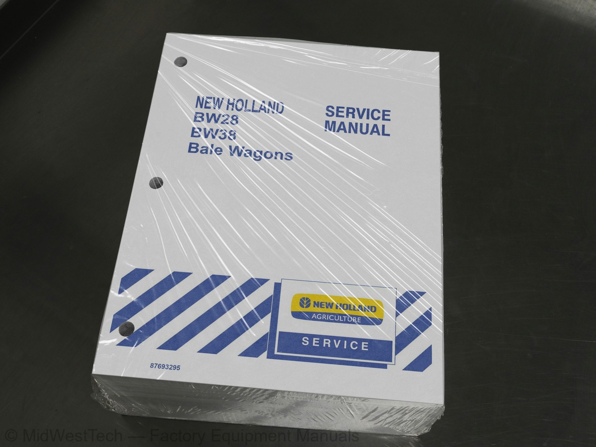
New Holland BW28, BW38 Bale Wagon Service Manual
1,561 pages · Publication 87693295
Added to your cart. View cart
- Models
- BW28, BW38
- Manual type
- Service Manual
- Pages
- 1,561
- Publication
- 87693295
- Condition
- Brand new
What's inside
From the manual's own table of contents: 349 sections, 700 entries. See sample pages (PDF, 555 KB)
Introduction1 topic
- Filtration
Specifications2 topics
- Pump
- Relief Valves
Closed Center1 topic
- System Diagram
System Operation8 topics
- Cooling Fan
- Fan-reversing
- First Table
- Second Table
- Tie Spikes
- Load Rack
- Rolling Rack
- Push-off Feet
Component Identification and Location6 topics
- Left-hand (LH) View
- Front View
- Right-hand (RH) View
- Rear View
- Plan View
- Bottom View
Show all 349 sections
Open-Center System (Double Gear Pump)4 topics
- Motors
- Back-pressure Valve
- Motor Circuit
- Steering/Brake Circuit
Solenoid Coil5 topics
- Replacement
- Removal
- Electrical Schematic - Main Manifold
- Electrical Schematic - Hydraulics
- Installation
Valve2 topics
- Disassemble
- Assemble
Valve Styles and Functions5 topics
- Two-way Two-position Poppet Valves
- Normally Closed
- Normally Open
- Three-way Two-position Spool Valves
- Electrical Schematic - Fan Relay
Cartridge Valves (Pressure- or Pilot-operated)3 topics
- Brake-pressure Valve (BPV)
- Load-sensing Shuttle Valve (LSSV)
- Load-holding Valve
Non-solenoid Cartridge Valve1 topic
- Adjustment
Relief Valves5 topics
- Fan Sensing Relief (FSRV) – 76 bar (1100 psi)
- Rolling Rack Relief (RRRV) – 76 bar (1100 psi)
- Second Table Relief (STRV) – 145 bar (2100 psi)
- Fan-Reversing Relief – 110 bar (1600 psi)
- Power Steering Relief (PSRV) – 158 bar (2300 psi)
Gear Pump2 topics
- Repair Information
- Tools Required
Inspection1 topic
- General
Pump Body1 topic
- Start-up Procedure
Repair Information2 topics
- Required Standard Tools
- Special Tools
Front Shaft Bearing1 topic
- Inspection
Pump Output Test3 topics
- Open-center Circuit (Gear Pump)
- Closed-center Circuit (Piston Pump)
- Case Drain Flow (Piston Pump)
Open-center System (Gear Pump)3 topics
- No Functions Will Operate
- All Functions are too Slow
- All Functions are too Fast
Closed-center System (Piston Pump)11 topics
- System Not Developing Adequate Pressure
- System Not Developing Adequate Flow
- Hydraulic System Overheating
- Cooling Fan Stops Before Achieving Full Operating Speed
- Pumps
- Valve Manifold and Components
- Flow Dividers
- Motor Flow Divider (MFD)
- Load Rack Valve
- Filters
- Capacity
Labor Guide13 topics
- Spool Valve
- Cartridge Valve
- Relief Valve
- Flow Divider
- Check Valve
- Orifice
- Load Holding Valve
- Gear Pump
- Piston Pump
- Orbit Motors
- Cylinders
- Reservoir
- Testing
Ground Point Locations6 topics
- Ground H
- Ground 1
- Ground 2
- Ground 3
- Ground 4
- Ground 10
Electrical Panel Locations4 topics
- Access to Rear Electrical Panel (Near Engine)
- Junction Block (W-01)
- Junction Block (W-01) Connections
- Access to Cab Console Panel
Fuses1 topic
- Fuse Removal
Relays7 topics
- Relay Operation
- Mini Relays
- Micro Relays
- Fuses
- Circuit Breakers
- Relays
- Junction Box
Relay1 topic
- Test Procedure
Switches4 topics
- Button Switch
- Rocker Switch
- Momentary Rocker Switch
- Multi-Function Handle (MFH) Switches
Fuses, Relays, and Switches1 topic
- Switch and Relay Contacts
Wire Harness Identification1 topic
- Wire Color Codes
Wiring Harness - Component Diagram137 topics
- Connector X001 - Transmission Speed Sensor
- Connector X002 - Turbine Speed Sensor
- Connector X003 - Engine Speed Sensor
- Connector X004 - Transmission INPUT/OUTPUT
- Connector X007 - Transmission Controller
- Connector X008 - Transmission Controller
- Connector X010 - Right Console Harness (RC) to Main Harness (MH)
- Connector X011 - Check Transmission Indicator
- Connector X012 - Range Inhibit Indicator
- Connector X013 - Speedometer
- Connector X014 - Diagnostics Connector
- Connector X015 - Piston Pump Manifold (PPM)
- Connector X016 - Piston Pump Manifold (PPM)
- Connector X017 - Piston Pump Manifold (PPM)
- Connector X018 - Right Side Sensor
- Connector X019 - Bale Loader Down Sensor
- Connector X020 - 1st Table Up Limit Sensor
- Connector X021 - Gear Pump Manifold (GPM)
- Connector X022 - Fuel Solenoid
- Connector X023 - 2nd Table 50 ° Sensor
- Connector X024 - 2nd Table Up Sensor
- Connector X025 - 2nd Table Down Sensor
- Connector X026 - Left Push-Off Feet Home Sensor
- Connector X027 - Electronic Controller
- Connector X028 - Electronic Controller
- Connector X029 - Electronic Controller
- Connector X030 - Gate Switch
- Connector X033 - AC Blower Resistor
- Connector X034 - AC Blower Motor
- Connector X038 - Fan Reverse Solenoid (if equipped)
- Connector X039 - Fuel Level Indicator
- Connector X040 - Park Brake Indicator
- Connector X041 - Alternator Indicator
- Connector X042 - Oil Pressure Indicator
- Connector X043 - Throttle Position Sensor
- Connector X045 - Start Solenoid Motor
- Connector X048 - Ignition Switch
- Connector X050 - Operator Panel
- Connector X054 - Cab Interior Light
- Connector X055 - Cab Interior Light
- Connector X062 - Engine Temperature Indicator
- Connector X066 - RH Shifter
- Connector X067 - Fuel Sender
- Connector X068 - Fuel Gauge
- Connector X069 - Oil Pressure Gauge
- Connector X069 - Oil Pressure Sensor
- Connector X070 - Alternator Bias Resistor
- Connector X071 - Alternator
- Connector X075 - Turn Signal - High/Low Beam Switch
- Connector X078 - Axle Range Switch
- Connector X080 - Tachometer
- Connector X082 - Voltmeter
- Connector X083 - Load Rack Down Sensor
- Connector X089 - AC High Pressure Switch
- Connector X090 - AC Compressor Clutch
- Connector X092 - Cell Phone Jack
- Connector X093 - Communication Radio Jack
- Connector X094 - HVAC Mode Select Switch
- Connector X095 - Fan Speed Switch
- Connector X104 - Heater Motor (if equipped)
- Connector X105 - AC Blower Motor
- Connector X106 - Thermostat Switch
- Connector X107 - AC Low Pressure Switch
- Connector X110 - Windshield Wiper Switch (if equipped)
- Connector X111 - Windshield Wiper Motor (if equipped)
- Connector X113 - Brake Light Switch
- Connector X114 - Brake Flow Switch
- Connector X115 - Brake Boost Motor
- Connector X116 - Flasher Module
- Connector X117 - Hazard Lights Switch
- Connector X118 - Road/Field Light Switch
- Connector X119 - Console Overhead Light
- Connector X120 - Right Front Work Light
- Connector X121 - Left Front Work Light
- Connector X122 - Left Rear Work Light
- Connector X123 - Side Work Light
- Connector X124 - Rear Work Light
- Connector X125 - Left Brake Light
- Connector X126 - Right Brake Light
- Connector X127 - Left Headlamp
- Connector X128 - Right Headlamp
- Connector X131 - Water/Coolant Level Switch
- Connector X133 - Engine Coolant Temperature Gauge
- Connector X134 - Water Temperature Sensor
- Connector X136 - Axle Range Motor
- Connector X137 - Right Rear Work Light (if equipped)
- Connector X144 - Left Side Hazard Light
- Connector X145 - Right Side Hazard Light
- Connector X146 - Front Left Hazard Light
- Connector X147 - Front Right Hazard Light
- Connector X148 - Rear Left Hazard Light
- Connector X149 - Rear Right Hazard Light
- Connector X150 - Rear Left Turn Light
- Connector X151 - Rear Right Turn Light
- Connector X152 - Main Harness to Rear Load Rack Harness
- Connector X153 - Cab Dash Harness to Right Console Harness
- Connector X154 - Tie Spike Sensor (BW28)
- Connector X154 - Tie Spike Sensor (BW38)
- Connector X155 - 1st Table Left Trip Sensor
- Connector X157 - Multifunction Handle (MFH)
- Connector X159 - Indicator Panel, LH Turn
- Connector X160 - Indicator Panel, Hazard Lights
- Connector X161 - Indicator Panel, High Beam
- Connector X162 - Indicator Panel, Right Turn
- Connector X171 - Air Seat Assembly
- Connector X171 - Radio (if equipped)
- Connector X173 - Right Speaker
- Connector X173 - Right Push-off Feet Home Sensor
- Connector X174 - Left Speaker
- Connector X174 - Front CAN Termination Resistor
- Connector X202 - Fan Gear Pump Oil Solenoid
- Connector X207 - Fuel Gauge
- Connector X209 - Fuel Gauge
- Connector X210 - Fuel Gauge
- Connector X211 - Voltmeter
- Connector X212 - Voltmeter
- Connector X214 - Water Temperature Gauge
- Connector X215 - Water Temperature Gauge
- Connector X216 - Water Temperature Gauge
- Connector X217 - Engine Oil Pressure Gauge
- Connector X218 - Engine Oil Pressure Gauge
- Connector X219 - Engine Oil Pressure Gauge
- Connector X220 - Turn Signal/High-Low Beam Switch
- Connector X221 - Right Console to Overhead Instruments
- Connector X222 - Right Console to Overhead Instruments
- Connector X224 - Diode Module
- Connector X226 - Main Harness to Transmission Harness
- Connector X232 - Alternator (Bosch)
- Connector X233 - Alternator (Bosch)
- Connector X234 - Neutral Start/Backup Switch
- Connector X236 - AC High Pressure Switch
- Connector X237 - Fuel Sender
- Connector X238 - Junction Block
- Connector X239 - Junction Block
- Connector X240 - Junction Block
- Connector X241 - Junction Block
- Connector X242 - Junction Block
Visual Inspection8 topics
- Battery Age and Date Coding
- Overcharging and Undercharging
- Battery Case
- Electrolyte
- Intercell Connections and Terminal Posts
- Positive Plates
- Negative Plates
- Sulfation
Testing the Battery - General2 topics
- Battery State of Charge - Open Circuit Voltage
- Battery Capacity Test (Load Test) - High Rate Discharge
Alternator2 topics
- Maintenance
- Belt Tension
Alternator Connections (ISKRA)4 topics
- Bosch Technical Data
- Bosch Torque Specifications
- ISKRA Technical Data
- ISKRA Torque Specifications
Field Excitation Resistor (R-06)1 topic
- Alternator and Voltage Regulator Precautions
Cab Hazard/Warning Lights Removal1 topic
- Cab Turn Signal\Flasher Bulb Replacement
Headlights (Low-beam)2 topics
- Path 1 (To Marker Light Fuse F-25)
- Path 2 (To High Beam Relay K-06)
Headlights (High-beam)7 topics
- Path 1 (Loader Work Light E-21)
- Path 2 (Top LH Work Light E-19)
- Path 2 (Top RH Work Light E-18)
- Path 3 (LH Second Table Work Light E-20)
- Path 3 (RH Second Table Work Light E-08) If Equipped
- Path 3 (RH Console Light E-17)
- Path 4 (Rear Work Light E-22)
Flasher Module (A-02) Left-Grouped Circuits3 topics
- LH Front Hazard Light (E-34)
- LH Side Hazard Light (E-32)
- LH Rear Hazard Light (E-36)
Flasher Module (A-02) Right-Grouped Circuits5 topics
- RH Front Hazard Light (E-35)
- RH Side Hazard Light (E-33)
- RH Rear Hazard Light (E-37)
- Left-grouped Circuits
- Right-grouped Circuits
Interior Lights2 topics
- RH Console Light (E-17)
- Dome Light (E-41)
Indicator Lights1 topic
- Light Indicator Display (E-40)
Second Table2 topics
- Standard Tiers
- Tie Tiers
Electronic Controller (ECU-02) Connections3 topics
- Connector X027 J-1
- Connector X028 J-2
- Connector X029 J-3
Stack Command ™ Control Keys2 topics
- Spikes
- Other Keys
Safety Gate Switch (S-02)3 topics
- Safety Gate Circuit
- Introduction
- Operation
Load Rack Home Sensor (B-13)3 topics
- Engine
- Fuel System
- Cooling System
Overhaul2 topics
- Mounting on a Test Stand
- Removal from Test Stand
Injection Pump1 topic
- Timing
Piston1 topic
- Disassembly
Piston and Connecting Rod1 topic
- Assembly
Check Engine Air Filter Outer Element1 topic
- Cleaning
Muffler1 topic
- Remove
Engine Oil and Filter1 topic
- Change Interval
Oil Sump and Suction Tube1 topic
- Overhaul
Rear Driveline1 topic
- Repair
Front Wheel Bearings1 topic
- Checking the Adjustment
Wheel Assembly1 topic
- Measurement
Knuckle Bushing1 topic
- Removal and Installation Tool
Noise3 topics
- Rear Axle Noise
- Gear Noise
- Bearing Noise
Vibration2 topics
- Typical Low-Speed Vibrations
- Typical High-Speed Vibrations
Vibration Diagnosis Procedure1 topic
- Vehicle Vibration Road Test
Ring Gear and Drive Pinion Teeth5 topics
- Fractured Ring Gear Teeth
- Scored and Scuffed Teeth
- Overheated Ring Gear and Pinion
- Pitted Drive Pinion Teeth
- Fractured Drive Pinion Teeth
Differential Gear Failures5 topics
- Shock Fractured Side Gears and Pinions
- Scoring and Seizure of Spider Arm and Side Pinions
- Fatigue Fractured Side Gears
- Worn Splines in the Side Gears
- Scored or Worn Surfaces on Thrust Washers
Planetary Assembly4 topics
- Worn Teeth in the High Speed Clutch Plate
- Worn Teeth in the Differential Bearing Adjuster
- Worn or Scored Bronze Pinion Pins
- Pitted Teeth on the Sliding Clutch Gear and Idler Pinions
Differential Carrier2 topics
- Loose Bearing Adjuster Lock
- Worn Pinion Pilot Bearing Bore
Gear Support Case Assembly2 topics
- Worn Bearing Hub in Gear Support Case
- Worn Bearing Rollers
Axle Shaft2 topics
- Twisted or Broken Axle Shaft
- Fracture of Axle Shaft at Flange
Axle Housing4 topics
- Axle Housing Bent
- Hazard Alert Messages
- Replace Worn or Damaged Parts
- Clean, Dry and Inspect Parts
Pinion Shaft1 topic
- Cleaning and Inspection
Electric Shift System1 topic
- Shift Unit Components
Electrical Operation2 topics
- Unit in Low Range Shifting to High Range
- Unit in High Range Shifting to Low Range
Mechanical Operation4 topics
- Low to High Range or High to Low Range
- Testing the Electric Shift
- Slider Block Inspection
- Checking Shift Fork Position and Alignment
Shift Unit7 topics
- Removal of Shift Unit
- Installation of Shift Unit
- Disassembly of Shift Unit
- Cleaning the Shift Unit
- Lubricating the Shift Unit
- Sealing the Shift Unit
- Assembly of the Shift Unit
Inside this manual
Real pages from this service manual (1,561 pages). Open the sample pages (PDF, 555 KB)
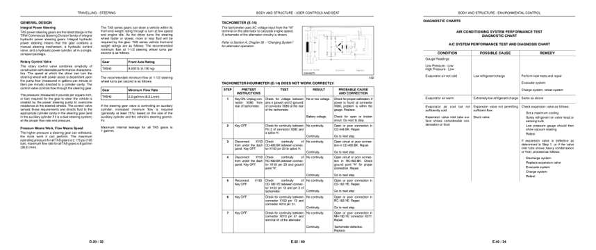
- Specifications, page 1,073: TRAVELLING - STEERING
- Diagram, page 1,313: BODY AND STRUCTURE - USER CONTROLS AND SEAT
- Troubleshooting, page 1,385: BODY AND STRUCTURE - ENVIRONMENTAL CONTROL
This is a service manual
Here's how it compares to the other manual types.
Service manual
Factory repair procedures and technical information such as specifications, troubleshooting, and wiring and hydraulic diagrams, for the models and systems the manual covers. See What's inside for its topics.
Operator's manual
Safe operation, controls, maintenance schedules, lubrication points, inspections, and basic checks. Repair procedures are in the service manual.
Parts manual
Illustrated diagrams with factory part numbers for identifying components and ordering parts. Repair procedures are in the service manual.
Engine service manuals are sometimes sold separately, since certain machine models were offered with more than one engine option.
What it's used for
Factory manual for in-house farm and construction shop use. Straightforward, complete, and easy to follow. It contains the OEM information dealership service departments and parts counters use to diagnose problems, identify components, and perform maintenance or repairs correctly.
Service shops and owner/operators who repair their own equipment
Identifying correct parts and seeing how assemblies come apart and go back together
Keeping equipment running with less downtime
Factory manual, 1,561 pages
Quantity one is the manual described above.
Fast free USA shipping
Ships in 1 business day.
60-day returns
Free if the mistake is ours. A manual ordered in error must come back unopened in its shrink-wrap; you pay return shipping and a 20% restocking fee applies. Return policy
Binder not included
Manuals over about 300 pages may need a standard 3-ring binder, which you can buy locally to keep the pages organized for shop use.
Questions about model, serial number, engine coverage or contents? Contact us before purchasing and we'll help confirm it's the right manual. Please verify the manual type, machine model, serial number range and engine coverage before purchasing: manuals ordered in error carry a 20% restocking fee (return policy).