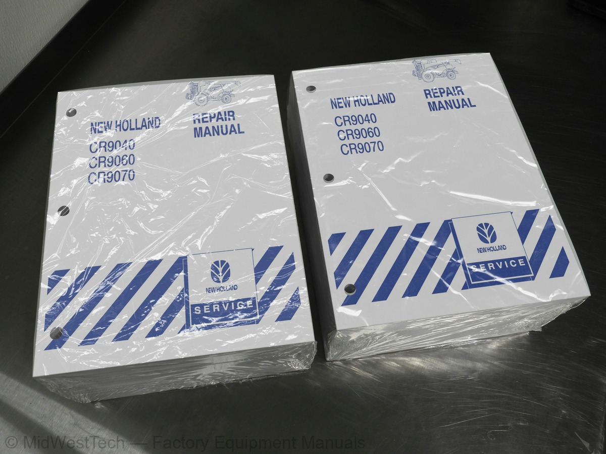
New Holland CR9040, CR9060, CR9070 Combine Service Manual
3,587 pages · Publication 87682452
Added to your cart. View cart
What's inside
From the manual's own table of contents: 466 sections, 700 entries. See sample pages (PDF, 701 KB)
Show all 466 sections
Cooling Fan Drive4 topics
- Disassembly
- Inspection
- Assembly
- Installation
Radiator Unit1 topic
- Removal
Rotary Screen Seal1 topic
- Replacement
Flexplate6 topics
- Component Repair -- Bearing and Race Removal/Installation
- Component Repair -- Clutch Cylinder Bushing Removal/Installation
- Clutch Installation
- Unloader Clutch Shimming Process
- Main Clutch Shimming Installation
- Clutch Temperature Sender Shim Installation
Disassembly1 topic
- Distance Ring Combinations Table
Multi Function Valves4 topics
- Charge Check Valve 8a -- 9a
- Pressure Limiter 8b -- 9b
- High Pressure Relief Valve 8c -- 9c
- Bypass Valve 8d -- 9d
Servo Valve2 topics
- System in Neutral
- Servo Solenoid Valve 10a Energized
Hydrostatic Drive Motor Valves3 topics
- Shuttle Spool Valve
- Flushing Relief Valve
- Pressure Release Valve Circuit
Hydrostatic Pump and Drive Motor Identification Numbers2 topics
- Pump Characteristics
- Drive Motor Characteristics
Control Valve1 topic
- Overhaul
29 212 Charge Pump Installation1 topic
- Major Repairs
29 218 Multi-Function Valve1 topic
- Adjustment
29 218 Motor Charge Relief Valve -- Style 11 topic
- Check
Parking Brake Override1 topic
- Manual Override
Bleeding the Hydraulic Parking Brake Caliper1 topic
- Parking Brake Caliper -- Cross Section View
Hydraulic Symbols5 topics
- High Pressure Circuit Diagram, Main
- High Pressure Circuit Diagram, Main (with Autoguidance Steering Valve)
- Main Frame Stack Valve
- Main Frame Stack Valve (with Autoguidance Steering Valve)
- Feeder Stack Valve
Schematic Diagrams3 topics
- Low Pressure System
- Low Pressure System with Positive Straw Discharge
- Model Year 2005 and Later
Closed Center Load Sensing (CCLS) Variable Displacement Pump2 topics
- Principal of Pump Operation -- Fixed Vs. Variable Displacement
- Flow and Pressure Compensating Valves
Hydraulic Circuit Operation4 topics
- Low Pressure Standby
- High Pressure Circuit High Demand
- High Pressure Circuit Low Demand
- Controlling Maximum System Pressure
CCLS Pump Pressure and Flow Testing4 topics
- CCLS Pump Low Pressure Standby
- CCLS Pump High Pressure Standby
- CCLS Pump Load Sensing Circuit
- CCLS Pump Flow Test
Steering Testing3 topics
- Steering Test
- Steering Relief Valve Pressure Test
- Hydraulic Cleaning Fan Flow Test
Low Pressure System Testing5 topics
- Low Pressure System – Chaff Spreader Pressure Test
- Chaff Spreader/PSD Pressure Test
- Low Pressure System – Regulated Pressure Test
- Low Pressure System – Individual Circuit Testing
- Low Pressure System – Pump Flow Test
Axle Types3 topics
- Axle Center Section
- Heavy Duty Adjustable Steering Axle (HDASA)
- Powered Rear Axle (PRA)
Toe In Adjustment2 topics
- Tie Rod
- Steering Cylinders
Wheel Bearing1 topic
- Repacking
Hub and Kingpin Casting1 topic
- Hub and Kingpin -- Exploded View
Bushing Replacement12 topics
- Valve Retainer Tool
- Split Ring Assembly Hood
- Bushing Driver
- Bushing Driver Ring
- Assembly, Shaft Removal Tool
- Wheel Motor Bar
- Parts Specifications - Shaft Removal Tool and Rotational Torque Tool
- Rotational Torque Tool
- Bar, Rotational Torque Tool
- Radial Clip Installation Tool
- Setting Tool
- Tool Holder
Rear Axle1 topic
- Hydrostatic Motor - Exploded View
A/C Cycle1 topic
- Air Conditioning Process
Climate Control1 topic
- Automatic Temperature Control (ATC)
Fault Codes2 topics
- Problem Solving Pressure Test Results and Temperature/Pressure Chart
- Air-conditioning Temperature/Pressure Chart
The Digital Multi-Meter6 topics
- General Operation
- Measuring Voltage (Volts)
- Measuring Current (Amps)
- Measuring Resistance (Ohms)
- Continuity (Buzzer) Test
- Summary
CCM Power and Ground Supplies3 topics
- CCM1 Module
- CCM2 Module
- CCM3 Module
Combine Control Module (CCM) Removal and Installation6 topics
- CCM Identification
- Instructional Seat Removal
- Removal of CCM
- CCM Installation
- Software Installation
- Instructional Seat Installation
Cab Electrical Connectors X002 and X0033 topics
- Removal of Rear Speaker Panel
- Connector Locations
- Installation of Rear Speaker Panel
Fault Archive Screen9 topics
- Active Alarms
- Active Errors
- Error History
- Service Setup Screen
- Display Setup Screen
- CAN Status Screen
- Settings Screen
- Inputs
- Outputs
55 000 Introduction7 topics
- Schematic Frames
- Power Distribution
- Machine Options
- Harnesses
- Wire Harness Designations
- Sensors
- Actuators
Alarms1 topic
- Checking Controller Status
Troubleshooting a Module Offline Alarm1 topic
- Troubleshooting Steps
Short Circuit1 topic
- IntelliView Monitor Branch
Harvest Guidance System (HGS) Connector Locations3 topics
- DGPS Branch
- RHM Branch
- Diagnostic Jack Branch
Troubleshooting Leg 211 topics
- ECU Branch
- HHC Branch
- ASP Branch
- Front Frame Harness
- CCM3 Branch
- CCM2 Branch
- Cab Main Harness
- Cab Roof Harness
- CCM1 Branch
- IVECO 10L Engine
- Cummins 9.0L Engine
General Engine Systems2 topics
- CNH Engine
- IVECO Engine
Starting System1 topic
- 24V Starting Circuit
Diagnostic Tests7 topics
- A -- Key Switch Power Supply Test
- B -- Key Switch Test
- C – Neutral Switch Test
- D – Neutral Start Relay Test
- E – 24 V Start Relay Test
- F – 24V Starter Motor Test
- G -- Starting Relay Test
Charging System -- Troubleshooting1 topic
- A -- Charging System Output Test
Description1 topic
- Grid Heater Circuits
Grid Heater Troubleshooting1 topic
- Test Points
Location2 topics
- Engine Control Unit (ECU) -- IVECO 10.3L
- Right Hand Control Module
Engine-Related Error Codes -- Automatic Shutdown3 topics
- Description
- Alarm Messages
- ECU Related Fault Codes
IVECO 10.3 l sensors1 topic
- Engine Oil Temperature/Pressure Sensor
CNH 9.0L Sensors6 topics
- Engine Camshaft RPM
- Engine Flywheel RPM
- Boost Pressure/Air Temperature Sensor
- Coolant Temperature Sensor
- Fuel Temperature Sensor
- Fuel Actuators
All Engines4 topics
- Rotary Screen Brush Actuator
- Fuel Level Sensor
- Air Filter Pressure Switch
- Fuel Pump Actuator
Power Mirror System1 topic
- Power Mirror Circuit Operation
Power Mirror Circuit Troubleshooting8 topics
- Mirror Fuse -- Power and Ground Test
- Mirror Adjust Switch S-27 Test
- Mirror Select Switch S-57 Test
- Left Hand Mirror Test
- Right Hand Mirror Test
- Additional Mirror Test
- Mirror Heat Switch S-19 Test
- Mirror Heat Circuits Test
Hydrostatic Ground Drive Electrical6 topics
- Overview
- Temperature Control System (TCS)
- Hydrostat Ground Drive Alarms
- Hydrostat Ground Drive Fault Codes
- Check Calibration of the Multifunction Handle
- Troubleshooting Multifunction Handle (MFH) Components
Park Brake4 topics
- Park Brake Alarms
- Park Brake Fault Codes
- Park Brake Electrical Component Troubleshooting
- Park Brake Switch S09
Service Brakes2 topics
- Service Brake Alarm Codes
- Service Brake Fault Codes
Gearshifting4 topics
- Special Conditions
- Gearshift Alarms
- Gearshift Fault Codes
- Gear Select Switch S24 Troubleshooting
Ground Speed RPM Sensor B171 topic
- Ground Speed RPM Fault Codes
Rear Wheel Assist (If Equipped)2 topics
- Rear Wheel Assist Fault Codes
- Rear Wheel Assist Switch S10 Troubleshooting
Reel Speed3 topics
- Operator Controls
- Configuration Settings
- Fault Codes
Header Height Control8 topics
- Header Height Sensors
- Calibration
- Head Accumulator Operation
- Header Operating Modes – Dynamic Ride Control
- Header Operating Modes -- Transport
- Header Operating Modes – Stubble Height
- Header Operating Modes -- Autofloat
- Header Operating Modes – Pressure Compensation
Feeder Engage6 topics
- Feeder Engagement Requirements
- Conditions that Prevent Feeder Engagement
- Feeder Engage – Alarms
- Feeder Engage – Error Codes
- Feeder Engage Circuit
- Feeder Engage – Troubleshooting
Feeder Speed (optional)3 topics
- Feeder Speed Adjust
- Feeder Speed Errors
- Feeder Speed -- Troubleshooting
Feeder Reverser3 topics
- Feeder Reverser – Alarms
- Feeder Reverser – Fault Codes
- Feeder Reverser -- Troubleshooting
Advanced Stone Protection (ASP) SYSTEM4 topics
- Stone Ejection System
- ASP System – Alarms
- ASP System – Error Codes
- ASP System – Troubleshooting
55 000 Thresher System5 topics
- Thresher Engage
- Thresher Disengage
- Thresher Alarms
- Thresher Errors
- Troubleshooting Thresher System
Rotor Speed4 topics
- Rotor Speed Adjust
- Rotor Speed Alarms
- Rotor Speed Errors
- Rotor Speed Troubleshooting
Concave Clearance4 topics
- Concave Clearance Adjust
- Concave Clearance Alarms
- Concave Clearance Errors
- Concave Clearance Troubleshooting
Self-Leveling Cleaning Shoe1 topic
- Alarms
Cleaning Fan Motor (Hydraulic)1 topic
- Fault Code
Cleaning System Sensors4 topics
- Lateral Inclination Sensor B02
- Fan Speed Switch S15
- Cleaning Fan RPM Sensor B16
- Left Returns RPM Sensor B06
Inside this manual
Real pages from this service manual (3,587 pages). Open the sample pages (PDF, 700 KB)
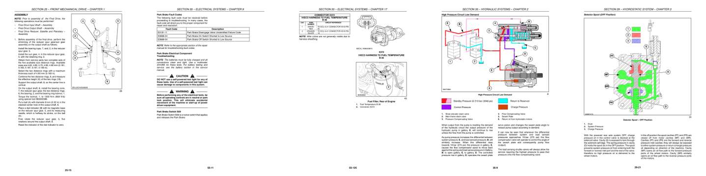
- Specifications, page 366: SECTION 25 -- FRONT MECHANICAL DRIVE -- CHAPTER 1
- Troubleshooting, page 1,246: SECTION 55 -- ELECTRICAL SYSTEMS -- CHAPTER 9
- Diagram, page 1,576: SECTION 55 -- ELECTRICAL SYSTEMS -- CHAPTER 17
- Color page, page 628: SECTION 35 -- HYDRAULIC SYSTEMS -- CHAPTER 2
- Color page, page 468: SECTION 29 -- HYDROSTATIC SYSTEM -- CHAPTER 3
Other manuals for this machine
Save 10% on 2 manuals, 15% on 3 or more. Other manuals for the CR9040, CR9060, CR9070 are listed below. Editions cover different serial number ranges: check the serial coverage and tick only the ones that match your machine.
Added to your cart. View cart
This is a service manual
Here's how it compares to the other manual types.
Service manual
Factory repair procedures and technical information such as specifications, troubleshooting, and wiring and hydraulic diagrams, for the models and systems the manual covers. See What's inside for its topics.
Operator's manual
Safe operation, controls, maintenance schedules, lubrication points, inspections, and basic checks. Repair procedures are in the service manual.
Parts manual
Illustrated diagrams with factory part numbers for identifying components and ordering parts. Repair procedures are in the service manual.
Engine service manuals are sometimes sold separately, since certain machine models were offered with more than one engine option.
What it's used for
Factory manual for in-house farm and construction shop use. Straightforward, complete, and easy to follow. It contains the OEM information dealership service departments and parts counters use to diagnose problems, identify components, and perform maintenance or repairs correctly.
Service shops and owner/operators who repair their own equipment
Identifying correct parts and seeing how assemblies come apart and go back together
Keeping equipment running with less downtime
Factory manual, 3,587 pages
Quantity one is the manual described above.
Fast free USA shipping
Ships in 1 business day.
60-day returns
Free if the mistake is ours. A manual ordered in error must come back unopened in its shrink-wrap; you pay return shipping and a 20% restocking fee applies. Return policy
Binder not included
Manuals over about 300 pages may need a standard 3-ring binder, which you can buy locally to keep the pages organized for shop use.
Other editions and similar models
Questions about model, serial number, engine coverage or contents? Contact us before purchasing and we'll help confirm it's the right manual. Please verify the manual type, machine model, serial number range and engine coverage before purchasing: manuals ordered in error carry a 20% restocking fee (return policy).