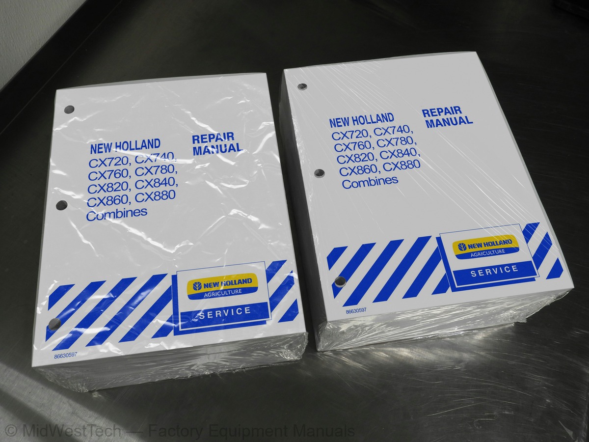
New Holland CX720, CX740, CX760, CX780, CX820, CX840, CX860, CX880 Combine Service Manual
3,811 pages · Publication 86630597
Added to your cart. View cart
What's inside
From the manual's own table of contents: 128 sections, 420 entries. See sample pages (PDF, 670 KB)
SECTION 90 - PLATFORM AND CAB9 topics
- Introduction
- Important information
- General instructions
- Spare parts
- Safety regulations
- Explanation of machine serial numbers
- Units of measure -- Conversion chart
- Minimum hardware tightening torques
- Drives
10 000 Specifications1 topic
- Description and Operation
10 001 Engine Overhaul--Introduction1 topic
- Injection Pump Timing Check
Show all 128 sections
10 001 Engine compression test6 topics
- Troubleshooting
- Specifications
- Disassembly and Repair
- Engine Removal
- Engine Installation
- Special Tools
10 200 Injection Pump Timing Check2 topics
- Adjustments and Diagnosis
- Maintenance
10 210 Fuel Lift Pump Sedimenter1 topic
- Component Overhaul
10 000 Walk Around16 topics
- The Iveco Engine
- Engine Block and Cylinder Liners
- Crankshaft
- Crankshaft Sealing Rings
- Connecting Rods
- Pistons
- Camshaft
- Timing System
- Flywheel
- Auxiliary Drivebelt
- Lubrication
- Oil Filter
- Oil Sump
- Cooling
- Electronically Controlled Injection System
- Pump Injector
10 000 General specifications3 topics
- Lubrication diagram
- Fuel supply system diagram
- Mechanical troubleshooting
10 102 70 Replacing the crankshaft front cover seal. Removal--Refitting1 topic
- of pump injector rocker arms
10 402 30 Thermostat. Removal--Refitting16 topics
- Main Clutch Disassembly
- Main Clutch Assembly
- Unload Clutch Disassembly
- Unload Clutch Assembly
- Gearbox
- Flexplate
- Special Tool
- Gearbox Disassembly
- Inspection
- Bearing and Race Removal/Installation
- Clutch Cylinder Bushing Removal
- Clutch Cylinder Bushing Installation
- Gearbox Assembly
- Tightening Torques
- Gearbox shafts
- Shifting diagram
21 145 Traction gearbox - Assembly5 topics
- Wheel bolt - Replacement
- Planetary final drive - R./ I
- Planetary final drive -- D./A
- Final drive - R./ I
- Final drive D./A
29 000 Specifications3 topics
- Hydrostatic Drive Schematic For C720, 740 and 760 Machines
- Hydrostatic Drive Schematic For C780, 820, 840, 860 and 880 Machines
- Explanation of Hydraulic Symbols
29 000 Powered Rear Axle (RWD) Introduction5 topics
- Equa-Trac II Control Valve
- Drain Valve
- Powered Rear Axle Motors
- Powered Rear Axle Hydraulic Schematic
- Main Hydrostatic System
29 218 Installing the Shaft (Pump and Motor)10 topics
- Brake linings -- Replacement
- Brake cilinders
- Bleeding the brakes
- Brake shoe and brake disc -- R./I
- Parking brake shoe and parking brake disc -- R./I
- Parking brake -- Manual release
- Parking brake piston travel and adjustment
- Parking brake linings -- Replacement
- Bleeding the hydraulic parking brake cilinder
- Parking brake cilinder -- D./A
35 000 Specifications6 topics
- High Pressure Circuit Diagram
- High Pressure System Component Locations
- High Pressure System Component Descriptions
- Low Pressure Circuit Diagram
- Low Pressure System Component Locations
- Low Pressure System Component Descriptions
35 000 Introduction17 topics
- CCLS Hydraulic Pump (High Pressure) Installation
- Fixed Displacement Hydraulic Pump (Low Pressure) Installation
- Fault Finding
- Low Pressure Standby
- High Pressure Standby
- Load Sensing Circuit Test
- Variable Flow Piston Pump Flow Test
- Steering Test
- Steering Circuit Pressure Test
- Steering Relief Valve Pressure Test
- Chaff Blower Motor Valve Pressure Test
- Low Pressure Test
- Low Pressure Pump Flow Test
- Hydraulic Pump Overhaul
- Main Stack Valve
- Feeder Stack Valve
- Low Pressure Valve Block
41 101 Powered Rear Axle Adjustment2 topics
- Height Position
- Track Width Position
41 000 Specifications44 topics
- Bolt Torque Specifications
- Introduction and General Information
- Troubleshooting - Powered Rear Axle
- Powered Rear Axle Hydraulic Pressure Test
- Test Pressures vs. Machine Operation Mode
- Powered Rear Axle Leak Test
- Powered Rear Axle Solenoid Valve Testing
- Start-up Procedure for Powered Rear Axle
- Wheel Motor Maintenance Schedule
- Equa-Trac II Valve
- Wheel Motor
- Wheel Motor Overhaul
- A/C Cycle
- Refrigerant
- Testing and Troubleshooting, General
- Preliminary Troubleshooting and Testing
- Preliminary Diagnosis Chart
- Test Procedure - Stabilizing the System
- A/C System Performance Test and Diagnosis Chart
- Gauge Readings and Interpretations
- Compressor Description
- Compressor Removal
- Compressor Installation
- Clutch Removal
- Clutch Installation
- Labor Guide
- Condenser Description
- Condenser Removal
- Condenser Installation
- Cool Box Description
- Cool Box Damper Actuator Removal
- Cool Box Damper Actuator Installation
- High / Low Pressure Cutout Switch Description
- High Pressure Switch Removal
- High Pressure Switch Installation
- Low Pressure Switch Removal
- Low Pressure Switch Installation
- Receiver / Dryer Description
- Receiver / Drier Troubleshooting
- Receiver / Drier Removal
- Receiver / Drier Installation
- Thermal Expansion Valve Description
- Thermal Expansion Valve Removal
- Thermal Expansion Valve Installation
55 000 Ground (Earth) Locations10 topics
- Front Lower Frame
- Left Side
- Rear Lower Frame
- Rear
- Grain Tank
- Engine Compartment, 7.5L only
- Engine Compartment, Iveco Cursor Only
- Engine Gearbox
- Cab Interior
- Electrical Connectors
55 000 Introduction21 topics
- Wiring Harness Repairs
- Digital Multi-Meter
- Electrical Test Procedures
- Circuit Components -- Basic Description and Testing
- Fuses
- Switches
- Flashers
- Resistance Devices
- Fluid Level Sender
- Potentiometers
- Potentiometer Adjustment
- Electromagnetic Devices
- Relays
- Solenoids
- PWM Solenoid Valves
- Sensors
- Temperature Sensors
- Pressure Sender
- Speed and Position Sensors
- Electronic Modules (CCM’s)
- CCM Power and Ground Supplies
55 000 Introduction -- Info-View Operation4 topics
- Can Network
- Alarms
- Troubleshooting a Module Offline Alarm
- Troubleshooting “A2000 Communication Lost” Alarm
55 000 Power Distribution System Circuit Operation105 topics
- Audio System Circuit Operation
- Exterior Lighting System
- Interior Lighting and Horn System
- Power Mirror System
- Power Seat System
- Schematic Index, Series 1206, 1212 and 1226 Only
- Schematic Index, Series 1238 to 1278
- Schematic, Series 1238 to 1278
- Schematic Index, 2003 Production, Series 1282 to 1336
- Schematic, 2003 Production, Series 1282 to 1336
- Schematic Index, 2004 Production, Series 1348 to 1372
- Schematic, 2004 Production, Series 1348 to 1372
- Schematic Index, 2005 Production, Series 1408 to 1444
- Schematic, 2005 Production, Series 1408 to 1444
- Service Info Menu
- Diagnose Info Menu
- Driveline
- Engine
- Threshing
- Grain Storage and Unload
- Precision Farming
- Lighting
- E0042 Current Sense Reverser
- E0043 Current Sense Lev Shoe
- E0044 Current Sense Concave CL
- E0045 Current Sense Bin Covers
- E0046 CCM1 Battery Voltage
- E0047 V Supply Feeder Clutch
- E0050 Isense Feeder Clutch
- E0052 Feeder Clutch Valve
- E0053 Chaff Spreader Valve
- E0059 Dual Range Valve
- E0061 Feeder Jog Forward Valve
- E0062 Fan Sp / Reverser Select
- E0063 Vertical Knife L
- E0064 Vertical Knife R
- E0065 Backup Alarm
- E0066 Rear Wheel Assist Valve
- E0067 Feeder Jog Reverse Valve
- E0068 Unload Tube Light Relay
- E0069 Covers / Concave Cl Sel
- E0070 Front Work Lights Relay
- E0071 Rear Work Lights Relay
- E0072 Side Work Lights Relay
- E0073 Field Lights Relay
- E0075 Leveling Shoe Motor
- E0076 Fan Speed Motor
- E0077 Reverser Motor
- E0078 Concave Clearance Motor
- E0079 Grain Bin Covers Motor
- E0080 HHC Module
- E0084 Voting Conflicts
- E0085 Voting Differences
- E0261 Lower Sieve Decrease - Rear Switch
- E0262 Upper Sieve Decrease - Rear Switch
- E0263 Lower Sieve Increase - Rear Switch
- E0282 Upper Sieve Increase - Rear Switch
- E0283 Moisture Temp Sensor
- E0284 Moisture Sensor
- E0285 Moisture Sensor +
- E0287 Upper Sieve Position Sensor
- E0288 Grain Yield Sensor
- E0289 Spreader Plate Position Sensor
- E0290 Lower Sieve Position Sensor
- E0293 CCM3 5V Ref Voltage 3
- E0294 CCM3 8V Ref Voltage
- E0295 CCM3 5V Ref Voltage 1
- E0296 CCM3 Keyswitch Voltage
- E0297 Current Sense Spreader Pl
- E0300 Current Sense Lower Sieve
- E0301 Current Sense Upper Sieve
- E0302 CCM3 Battery Voltage
- E0310 Bypass Unit Engage Output
- E0325 Upper/Lower Sieve Sel
- E0332 Spreader Plates Motor
- E0334 Lower Sieve Motor
- E0335 Upper Sieve Motor
- Fault Code Lists
- Fault Code Charts -- (NH675 TA/AB engine)
- Fault Code Charts -- (IVECO F2B or F3A engines)
- E0641 RHM 5V Reference Voltage
- E0643 MFH Position Input
- E0645 Gear Select Input
- E0646 CSW Feeder Reverse
- E0647 CSW Vertical Knives Left
- E0648 CSW Spreader Plates Right
- E0649 CSW HHC Auto Height
- E0650 CSW Vertical Knives Right Switch
- E0652 CSW Throttle Increase
- E0653 CSW HHC Compensation
- E0654 CSW Road Mode
- E0655 CSW Spreader Plates Left
- E0656 CSW Throttle Decrease
- E0657 CSW Reel Speed Set
- E0661 CSW Reel Speed Manual
- E0662 CSW Fan Speed Incr
- E0663 CSW Fan Speed Decr
- E0664 CSW Thresher Speed Inc
- E0665 CSW Thresher Speed Decr
- E0668 CSW Park Brake On
- E0669 CSW Park Brake Off
- E0670 CSW Concave Clear Decr
- E0671 CSW Concave Clear Incr
- E0672 CSW Upper Sieve Decr
- E0673 CSW Upper Sieve Incr
Op.60 Straw elevator clutch bearings - D./A1 topic
- Configuration of functional parts
Op.66 330 Drum bar replacement (universal drum)3 topics
- Types of drum concaves
- Concave specifications
- Setting of different types of concaves
Inside this manual
Real pages from this service manual (3,811 pages). Open the sample pages (PDF, 669 KB)
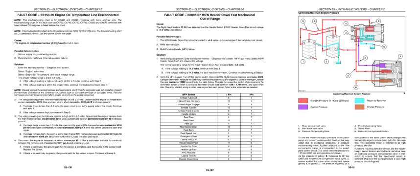
- Troubleshooting, page 2,279: SECTION 55 -- ELECTRICAL SYSTEMS -- CHAPTER 12
- Diagram, page 3,164: SECTION 55 -- ELECTRICAL SYSTEMS -- CHAPTER 16
- Color page, page 757: SECTION 35 -- HYDRAULIC SYSTEMS -- CHAPTER 2
This is a service manual
Here's how it compares to the other manual types.
Service manual
Factory repair procedures and technical information such as specifications, troubleshooting, and wiring and hydraulic diagrams, for the models and systems the manual covers. See What's inside for its topics.
Operator's manual
Safe operation, controls, maintenance schedules, lubrication points, inspections, and basic checks. Repair procedures are in the service manual.
Parts manual
Illustrated diagrams with factory part numbers for identifying components and ordering parts. Repair procedures are in the service manual.
Engine service manuals are sometimes sold separately, since certain machine models were offered with more than one engine option.
What it's used for
Factory manual for in-house farm and construction shop use. Straightforward, complete, and easy to follow. It contains the OEM information dealership service departments and parts counters use to diagnose problems, identify components, and perform maintenance or repairs correctly.
Service shops and owner/operators who repair their own equipment
Identifying correct parts and seeing how assemblies come apart and go back together
Keeping equipment running with less downtime
Factory manual, 3,811 pages
Quantity one is the manual described above.
Fast free USA shipping
Ships in 1 business day.
60-day returns
Free if the mistake is ours. A manual ordered in error must come back unopened in its shrink-wrap; you pay return shipping and a 20% restocking fee applies. Return policy
Binder not included
Manuals over about 300 pages may need a standard 3-ring binder, which you can buy locally to keep the pages organized for shop use.
Other editions and similar models
Questions about model, serial number, engine coverage or contents? Contact us before purchasing and we'll help confirm it's the right manual. Please verify the manual type, machine model, serial number range and engine coverage before purchasing: manuals ordered in error carry a 20% restocking fee (return policy).