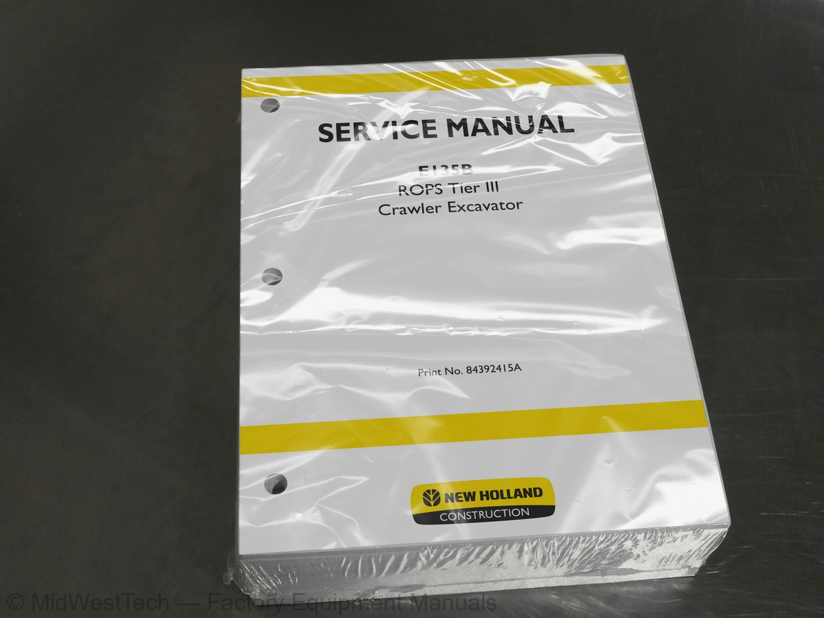
New Holland E135B ROPS Tier III Crawler Excavator Service Manual
1,039 pages · Publication 84392415A
Added to your cart. View cart
- Models
- E135B ROPS Tier III
- Manual type
- Service Manual
- Pages
- 1,039
- Publication
- 84392415A
- Condition
- Brand new
What's inside
From the manual's own table of contents: 1 sections, 234 entries. See sample pages (PDF, 502 KB)
General60 topics
- Main components
- Hydraulic components
- Excavator performance
- Engine data
- Engine characteristic curve
- Digging data (Monoblock Version)
- Version)
- equipped with blade)
- (Monoblock Version)
- (Triple Articulation Version)
- of the arms
- Group 1 - Mechatro Control System
- Preface
- Summary of Mechatro control system T2-1-2
- general
- Unload valve control
- Positive control & P-Q control
- Boom up conflux control
- control
- Arm-in anti-cavitation control
- Arm-out conflux control
- Bucket digging (dump) control.. T2-1-12
- Swing priority control
- Travel straight control
- N&B switch control (option)
- N&B solenoid relief valve control . T2-1-20
- Mechatro controller
- Summary of multi display
- Self diagnosis display
- function
- Trouble history diagnosis
- Trouble diagnosis mode
- schedule
- Adjusting procedure of display . T2-1-47
- Mechatro control equipment
- Group 2 - Hydraulic circuits
- Summary
- Hydraulic circuits and components
- N&B hydraulic circuit (option)
- Holding valve for boom & arm (option)T2-2-6
- Dozer hydraulic circuit
- circuits
- Neutral circuit
- Travel circuit
- Bucket circuit
- Boom circuit
- Swing circuit
- Arm circuit
- Combined circuit
- Electrical system main components
- Electrical system (Overall system)
- Electrical system diagram
- Electrical system diagram (No. 1)
- Electrical system diagram (No. 2)
- Electrical system diagram (No. 3)
- Electrical system diagram (No. 4)
- Electrical system diagram (No. 5)
- Electrical system diagram (No. 6)
- Wiring harness
- assembly
MECHATRO CONTROL SYSTEM173 topics
- MEAS
- NO.17 PRESS.SENSOR
- NO.16 PRESS.SENSOR
- COMMUNICATION OFF
- Washer motor relay
- Outline
- General view and hydraulic ports
- Hydraulic circuit diagram
- Specifications
- Hydraulic pump
- Operation
- Regulator
- Construction
- Adjusting the regulator
- Control curve of pump
- Pilot valve (ATT)
- Pilot valve (travel)
- Construction and operation
- Control valve
- Control valve ports
- Main relief valve (601)
- Over load relief valve (602, 606)
- Boom spool (301)
- Lock valve selector (211)
- Bypass cut valve (605)
- Swing shuttle valve cover (204)
- valve for N&B
- Installation
- Air breathing
- Outside view
- General view
- Swing motor
- Anti-reaction valve
- Swing reduction unit
- Hydraulic motor
- Valve casing section
- plunger
- Operation of relief valve
- Brake section
- Characteristics
- Rotation direction
- Hydraulic circuit
- Travel motor
- Reduction unit
- Operating description
- Reduction gear
- Hydraulic drives
- and Cautions to Be Exercised
- Preparation for Performance Tests
- Table
- Measurement of engine speed
- Measurement of hydraulic pressure
- Measuring travel performances
- Measuring swing performances
- performances
- bearing
- Engine control input/output
- (A-B-C adjustment)
- Judgment of actual thing at site
- troubleshooting
- Controller
- Troubleshooting by Error Codes
- Hydraulic system
- Electric systems
- Wiring checking procedure
- Trouble
- Engine
- Trouble diagnosis mode
- Tool table
- device
- Removing
- Installing
- unit
- Construction of travel motor unit
- Exploded view of reduction unit
- Exploded view of hydraulic motor
- Disassembling procedure
- Maintenance standard
- Sprocket
- Version equipped with blade
- Disassembly
- (with front idler)
- adjuster
- assy
- roller
- Removal
- Upper roller maintenance standard
- Tool table for upper roller
- lower roller
- Lower roller maintenance standard
- Tool table for lower roller
- Removal and installation of tracks
- Monoblock Version
- Triple articulation version
- Maintenance: monoblock version
- connection
- Replacement of bucket
- Removing the bucket
- Installing the bucket
- Bucket play adjustment
- Bucket teeth replacement
- Cylinders removal and installation
- Bucket Cylinder removal
- Bucket Cylinder installation
- Arm cylinder removal
- Arm cylinder installation
- Boom cylinders removal
- Boom cylinders installation
- Positioner cylinder removal
- Positioner cylinder installation
- Bucket cylinder
- Bucket cylinder disassembly
- Bucket cylinder assembly
- Arm cylinder
- Arm cylinder disassembly
- Arm cylinder assembly
- Positioner cylinder disassembly
- Positioner cylinder assembly
- Boom cylinders
- Boom cylinders disassembly
- Boom cylinders assembly
- Maintenance standards
- Inspection after disassembly
- External view
- System flow diagrams
- Engine serial number location
- Main specifications
- reassembling
- Disassembling
- Maintenance Service Data
- Engine general
- Basic engine
- Lubrication system
- Cooling system
- Inlet and exhaust system
- Electrical system
- List of tightening torque
- Special Tools
- Determining overhaul timing
- Testing compression pressure
- head and valve mechanism
- Removing injector
- Removing rocker shaft assembly
- Removing cylinder head bolt
- Removing valve and valve spring
- Removing valve stem seal
- Disassembling and inspecting flywheel
- Removing flywheel
- Removing flywheel housing
- case, timing gear and camshaft
- Removing crankshaft pulley
- Removing timing gear case
- Measuring timing gear backlash
- Measuring idler gear end play
- Removing idler gear
- Removing camshaft
- Separating camshaft gear
- plate
- Removing front plate
- crankshaft and piston
- Removing connecting rod cap
- upper part of cylinder liner
- Pulling out piston
- Removing piston ring
- Removing piston pin
- Removing main bearing cap
- Removing crankshaft
- and valve mechanism
- bushing and rocker shaft
- Replacing rocker bushing
- diameter
- Replacing valve guide
- Inspecting valve face
Inside this manual
Real pages from this service manual (1,039 pages). Open the sample pages (PDF, 502 KB)
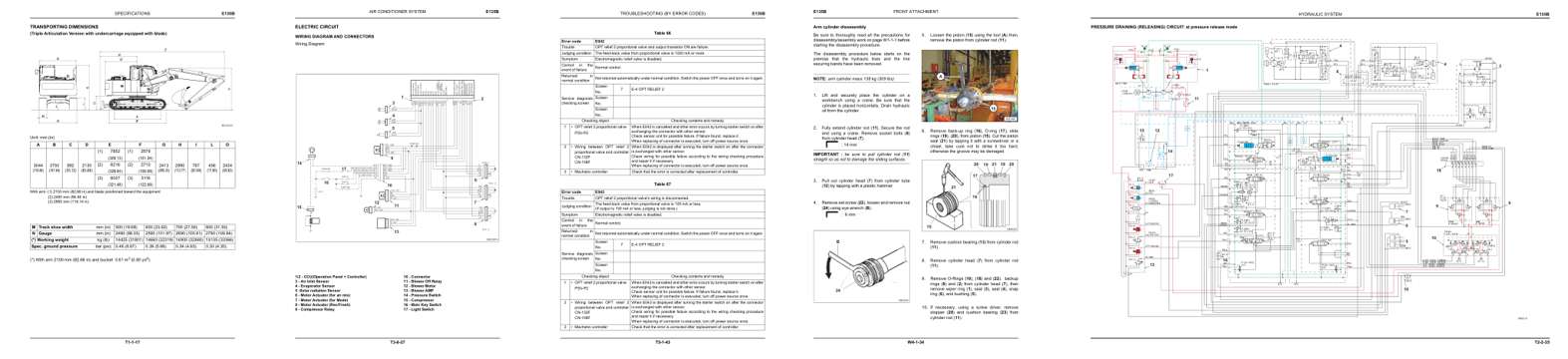
- Specifications, page 76: SPECIFICATIONS
- Diagram, page 364: AIR CONDITIONER SYSTEM
- Troubleshooting, page 476: TROUBLESHOOTING (BY ERROR CODES)
- Color page, page 839: FRONT ATTACHMENT
- Foldout diagram (color), page 180: HYDRAULIC SYSTEM
This is a service manual
Here's how it compares to the other manual types.
Service manual
Factory repair procedures and technical information such as specifications, troubleshooting, and wiring and hydraulic diagrams, for the models and systems the manual covers. See What's inside for its topics.
Operator's manual
Safe operation, controls, maintenance schedules, lubrication points, inspections, and basic checks. Repair procedures are in the service manual.
Parts manual
Illustrated diagrams with factory part numbers for identifying components and ordering parts. Repair procedures are in the service manual.
Engine service manuals are sometimes sold separately, since certain machine models were offered with more than one engine option.
What it's used for
Factory manual for in-house farm and construction shop use. Straightforward, complete, and easy to follow. It contains the OEM information dealership service departments and parts counters use to diagnose problems, identify components, and perform maintenance or repairs correctly.
Service shops and owner/operators who repair their own equipment
Identifying correct parts and seeing how assemblies come apart and go back together
Keeping equipment running with less downtime
Factory manual, 1,039 pages
Quantity one is the manual described above.
Fast free USA shipping
Ships in 1 business day.
60-day returns
Free if the mistake is ours. A manual ordered in error must come back unopened in its shrink-wrap; you pay return shipping and a 20% restocking fee applies. Return policy
Binder not included
Manuals over about 300 pages may need a standard 3-ring binder, which you can buy locally to keep the pages organized for shop use.
Other editions and similar models
Questions about model, serial number, engine coverage or contents? Contact us before purchasing and we'll help confirm it's the right manual. Please verify the manual type, machine model, serial number range and engine coverage before purchasing: manuals ordered in error carry a 20% restocking fee (return policy).