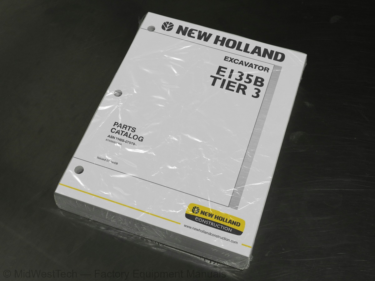
New Holland E135B Tier 3 Excavator Parts Catalog
613 pages · Publication 87659327
Added to your cart. View cart
- Models
- E135B Tier 3
- Manual type
- Parts Catalog
- Pages
- 613
- Publication
- 87659327
- Condition
- Brand new
What's inside
From the manual's own table of contents: 183 topics. See sample pages (PDF, 556 KB)
- FUEL FILTER & OIL FILTER ELEMENTS
- UPPER FRAME ASSEMBLY, PAGE 1 OF 2
- UPPER FRAME ASSEMBLY, PAGE 2 OF 2
- COUNTERWEIGHT INSTALLATION (YY60C00056F1), PART 1 OF 2
- COUNTERWEIGHT INSTALLATION (YY60C00056F1), PART 2 OF 2
- COUNTERWEIGHT INSTALLATION (YY60C00065F1)
- ENGINE ASSEMBLY
- ENGINE INSTALLATION (YY02P00017F1), PAGE 1 OF 2
- ENGINE INSTALLATION (YY02P00017F1), PAGE 2 OF 2
- RADIATOR INSTALLATION (YY05P00028F1)
- RADIATOR ASSEMBLY (YY05P00031F1)
- AIR CLEANER - COMPONENTS (YY11P00008F1)
- MUFFLER ASSEMBLY (YY12P00010F1)
- TANK INSTALLATION, FUEL (YY20P00037F1), PAGE 1 OF 2
- TANK INSTALLATION, FUEL (YY20P00037F1), PAGE 2 OF 2
- HYDRAULIC TANK ASSEMBLY (YY33H00049F1)
- POWER TAKE OFF ASSEMBLY (YY30P00009F1)
- SWING MOTOR ASSEMBLY (YY15V00021F1)
- VALVE INSTALLATION (MAIN HYDRAULIC VALVE) (YY64H00129F1)
- HYDRAULIC LINES, PUMP (YY30H00031F1), PAGE 1 OF 2
- HYDRAULIC LINES, PUMP (YY30H00031F1), PAGE 2 OF 2
- HYDRAULIC LINES, UPPER (YY03H00103F1), PAGE 1 OF 2
- HYDRAULIC LINES, UPPER (YY03H00103F1), PAGE 2 OF 2
- HYDRAULIC LINES, SWIVEL (YY19H00031F1)
Show all 183 topics
- HYDRAULIC LINES, RETURN (YY32H00026F1), PAGE 1 OF 3
- HYDRAULIC LINES, RETURN (YY32H00026F1), PAGE 2 OF 3
- HYDRAULIC LINES, RETURN (YY32H00026F1), PAGE 3 OF 3
- CONTROLS, OPERATOR (YY03M00052F1), PAGE 1 OF 2
- CONTROLS, OPERATOR (YY03M00052F1), PAGE 2 OF 2
- CONTROL BOX ASSEMBLY (YB03M00036F1)
- GRIP ASSEMBLY (YN03M01974F1)
- RADIO INSTALLATION & SWITCH INSTALLATION (YN54E00010F1 & LV50E00001F1)
- LEVER ASSEMBLY, PROPEL (YN50M00015F1)
- CONTROL LINES, REMOTE, PAGE 1 OF 3
- CONTROL LINES, REMOTE, PAGE 2 OF 3
- CONTROL LINES, REMOTE, PAGE 3 OF 3
- CONTROL LINES, MAIN (YY06H00061F1), PAGE 1 OF 2
- CONTROL LINES, MAIN (YY06H00061F1), PAGE 2 OF 2
- CONTROL LINES, VALVE (YY64H00125F1), PAGE 1 OF 2
- CONTROL LINES, VALVE (YY64H00125F1), PAGE 2 OF 2
- CONTROL LINES, PUMP (YY06H00041F1)
- PLATE INSTALLATION, FLOOR (YY03M00046F1)
- MIRROR INSTALLATION (FRONT) (YY52C00012F1)
- MIRROR INSTALLATION (REAR) (YY52C00014F1)
- CAB INSTALLATION (YY02C00024F1)
- CAB INSULATION INSTALLATION (YY26C00001F1)
- WINDOW ASSEMBLY, ROOF (YY02C01040F1%KL)
- WINDOW ASSEMBLY, FRONT (YN50C00005F1)
- DOOR ASSEMBLY, CAB (YB51C00004F1%KL)
- SEAT, PNEUMATIC CUSHIONING HEATED - COMPONENTS (YN25M00068F1)
- SEAT BELT ASSEMBLY (YN25M00053F1)
- GUARD INSTALLATION (YY21C00093F1), PAGE 1 OF 4
- GUARD INSTALLATION (YY21C00093F1), PAGE 2 OF 4
- GUARD INSTALLATION (YY21C00093F1), PAGE 3 OF 4
- GUARD INSTALLATION (YY21C00093F1), PAGE 4 OF 4
- GUARD INSTALLATION, FRONT (YY21C00085F1)
- GUARD ASSEMBLY, HANDRAIL (YY21C00095F1)
- GUARD ASSEMBLY, RIGHT-HAND SIDE (YY21C00082F1), PAGE 1 OF 2
- GUARD ASSEMBLY, RIGHT-HAND SIDE (YY21C00082F1), PAGE 2 OF 2
- GUARD ASSEMBLY, BOOM BASE (YY21C00081F1)
- GUARD ASSEMBLY, LEFT-HAND SIDE (YY21C00086F1), PAGE 1 OF 2
- GUARD ASSEMBLY, LEFT-HAND SIDE (YY21C00086F1), PAGE 2 OF 2
- GUARD ASSEMBLY, TOP (YY21C00061F1)
- GUARD ASSEMBLY, REAR (YY21C00091F1), PAGE 1 OF 2
- GUARD ASSEMBLY, REAR (YY21C00091F1), PAGE 2 OF 2
- COVER ASSEMBLY, UNDER (YY24C00014F1)
- PANEL ASSEMBLY, INSTRUMENT (YB17M00015F1), PAGE 1 OF 3
- PANEL ASSEMBLY, INSTRUMENT (YB17M00015F1), PAGE 2 OF 3
- PANEL ASSEMBLY, INSTRUMENT (YB17M00015F1), PAGE 3 OF 3
- GAUGE ASSEMBLY, CLUSTER (YN59S00021F2)
- CONTROLLER INSTALLATION (YY22E00112F1)
- RELAY BOX ASSEMBLY (YY24E00008F1)
- BATTERY INSTALLATION (YY72E00006F1)
- CONDITIONER ASSEMBLY, AIR (YY20M00017F1), PAGE 1 OF 3
- CONDITIONER ASSEMBLY, AIR (YY20M00017F1), PAGE 2 OF 3
- CONDITIONER ASSEMBLY, AIR (YY20M00017F1), PAGE 3 OF 3
- CONDITIONER ASSEMBLY, AIR (YN20M00113F1)
- DRIER ASSEMBLY, AIR (YY96V00009F1)
- COMPRESSOR ASSEMBLY, AIR (YX91V00001F1)
- CONDITIONER ASSEMBLY, AIR (YN20M00107F2), PAGE 1 OF 2
- CONDITIONER ASSEMBLY, AIR (YN20M00107F2), PAGE 2 OF 2
- ELECTRICAL ASSEMBLY, UPPER (HORN, BATTERY RELAY) (YY03E00006F1)
- LIGHT INSTALLATION (FRONT) (YY80E00008F1)
- TAIL LAMP ASSEMBLY (YY80E00013F1)
- HARNESS ASSEMBLY, UPPER (YY13E00052F1), PAGE 1 OF 11
- HARNESS ASSEMBLY, UPPER (YY13E00052F1), PAGE 2 OF 11
- HARNESS ASSEMBLY, UPPER (YY13E00052F1), PAGE 3 OF 11
- HARNESS ASSEMBLY, UPPER (YY13E00052F1), PAGE 4 OF 11
- HARNESS ASSEMBLY, UPPER (YY13E00052F1), PAGE 5 OF 11
- HARNESS ASSEMBLY, UPPER (YY13E00052F1), PAGE 6 OF 11
- HARNESS ASSEMBLY, UPPER (YY13E00052F1), PAGE 7 OF 11
- HARNESS ASSEMBLY, UPPER (YY13E00052F1), PAGE 8 OF 11
- HARNESS ASSEMBLY, UPPER (YY13E00052F1), PAGE 9 OF 11
- HARNESS ASSEMBLY, UPPER (YY13E00052F1), PAGE 10 OF 11
- HARNESS ASSEMBLY, UPPER (YY13E00052F1), PAGE 11 OF 11
- HARNESS ASSEMBLY, CAB (YB14E00018F1)
- HARNESS ASSEMBLY, UPPER (FLOOR PLATE) (YY13E00041F1)
- HARNESS ASSEMBLY, ENGINE (YY16E00005F1)
- LOWER GROUP
- SLEWING RING ASSEMBLY (YY40F00008F1)
- IDLER ASSEMBLY, CRAWLER (YY52D00010F1)
- IDLER ASSEMBLY (YY52D00007F1)
- IDLER ADJUST ASSEMBLY (YY54D00003F1)
- TRACK ROLLER ASSEMBLY (YY64D00028F1)
- ROLLER ASSEMBLY, UPPER (YY64D00004F1)
- PLATE ASSEMBLY (YY02F01300P1)
- LIGHT INSTALLATION, BOOM
- LIGHT ASSEMBLY (YW80S00001F1)
- HYDRAULIC LINES, ARM 2.84M (9FT-4IN)
- BUCKET INSTALLATION (LP61B00008F1)
- TOOLS & ACCESSORIES (YY01T00015F3)
- VALVE INSTALLATION (NIBBLER & BREAKER) (YY64H00130F1)
- CONTROLS, OPERATOR (NIBBLER & BREAKER) (YY55M00003F1)
- CONTROL LINES, VALVE (NIBBLER & BREAKER) (YY64H00096F1)
- ARM ASSEMBLY, LONG (NIBBLER & BREAKER) 2.84M (9FT-4IN) (YY12B00380P1)
- HYDRAULIC LINES, ARM (NIBBLER & BREAKER) 2.84M (9FT-4IN) (YY43H00134F1)
- CONNECTOR ASSEMBLY (NIBBLER & BREAKER) (YX43H01034F1)
- NAME PLATE INSTALLATION (NIBBLER & BREAKER) (YF22T00052F2)
- MIRROR INSTALLATION (OPERATOR'S CAB) (YN52C00032F1)
- ALARM ASSEMBLY (YY53E00002F2)
- VALVE ASSEMBLY, CONTROL (YY30V00058F1), PAGE 1 OF 5
- VALVE ASSEMBLY, CONTROL (YY30V00058F1), PAGE 2 OF 5
- VALVE ASSEMBLY, CONTROL (YY30V00058F1), PAGE 3 OF 5
- VALVE ASSEMBLY, CONTROL (YY30V00058F1), PAGE 4 OF 5
- VALVE ASSEMBLY, CONTROL (YY30V00058F1), PAGE 5 OF 5
- VALVE ASSEMBLY, PORT RELIEF (YN22V00002F1)
- VALVE ASSEMBLY, PORT RELIEF (YN22V00029F1)
- VALVE ASSEMBLY, OVERLOAD RELIEF (YN22V00035F1)
- VALVE ASSEMBLY, SOLENOID (YN35V00050F1)
- REDUCTION ASSEMBLY (SWING) (YY32W00004F1)
- MOTOR ASSEMBLY, PROPELLING (YY15V00015F1), PAGE 1 OF 2
- MOTOR ASSEMBLY, PROPELLING (YY15V00015F1), PAGE 2 OF 2
- SOLENOID VALVE ASSEMBLY (YN35V00052F1)
- CYLINDER ASSEMBLY, BOOM (YY01V00053F1)
- CYLINDER ASSEMBLY, ARM (YY01V00054F1)
- CYLINDER ASSEMBLY, BUCKET (YY01V00055F1)
- VALVE ASSEMBLY, PILOT (YN30V00111F1)
- VALVE ASSEMBLY, PILOT (PROPELLING) (YN30V00105F1)
- VALVE ASSEMBLY, SOLENOID (BLOCK) (YY35V00013F1)
- VALVE ASSEMBLY, SOLENOID (YN35V00048F1)
- VALVE ASSEMBLY, SOLENOID (YN35V00049F1)
- VALVE ASSEMBLY, SOLENOID (YN35V00051F1)
- VALVE ASSEMBLY, SOLENOID (LC35V00004F1, F2 & F3)
- VALVE ASSEMBLY, SOLENOID (YF30V00013F1), PAGE 1 OF 2
- VALVE ASSEMBLY, SOLENOID (YF30V00013F1), PAGE 2 OF 2
- JOINT ASSEMBLY, SWIVEL (YN55V00053F1)
- VALVE ASSEMBLY, BYPASS (YN30V00120F2)
- VALVE ASSEMBLY, RELIEF (YB22V00001F1)
- VALVE ASSEMBLY, RELIEF (YY22V00007F2)
- VALVE ASSEMBLY (SWING) (YY30V00067F1)
- ROCKER SHAFT
- CYLINDER HEAD COVER
- CAMSHAFT
- CRANKCASE
- LIFTING EYE & DRAIN PLUG
- MAIN BEARING
- TIMING GEAR CASE, PAGE 1 OF 2
- TIMING GEAR CASE, PAGE 2 OF 2
- FLYWHEEL HOUSING
- OIL PAN
- PISTON - ENGINE
- CRANKSHAFT & PULLEY
- FLYWHEEL
- TIMING GEAR
- AIR INTAKE SYSTEM
- EXHAUST SYSTEM (MANIFOLD), PAGE 1 OF 2
- EXHAUST SYSTEM (MUFFLER), PAGE 2 OF 2
- TURBOCHARGER ASSEMBLY (VA4918902750)
- TURBOCHARGER PIPING & CONNECTIONS
- OIL STRAINER
- OIL COOLER
- OIL FILTER
- CRANKCASE BREATHER
- WATER PUMP PULLEY
- ENGINE COOLING SYSTEM
- V-BELT
- FAN & SPACER
- FUEL SYSTEM
- INJECTOR PUMP INSTALLATION
- INTAKE MANIFOLD (AIR HEATER)
- ALTERNATOR MOUNTING
- ENGINE CONTROL (VA32G8701020)
- ENGINE HARNESS
Inside this manual
Real pages from this parts catalog (613 pages). Open the sample pages (PDF, 555 KB)
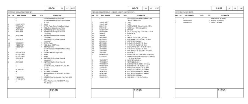
- Parts illustration, page 234: CONTROLLER INSTALLATION (YY22E00112F1)
- Parts illustration, page 378: HYDRAULIC LINES, ARM (NIBBLER & BREAKER) 2.84M (9FT-4IN) (YY43H00134F1)
- Parts illustration, page 576: INTAKE MANIFOLD (AIR HEATER)
Other manuals for this machine
Save 10% on 2 manuals, 15% on 3 or more. Other manuals for the E135B Tier 3 are listed below. Editions cover different serial number ranges: check the serial coverage and tick only the ones that match your machine.
Added to your cart. View cart
This is a parts manual
Here's how it compares to the other manual types.
Service manual
Factory repair procedures and technical information such as specifications, troubleshooting, and wiring and hydraulic diagrams, for the models and systems the manual covers. See What's inside for its topics.
Operator's manual
Safe operation, controls, maintenance schedules, lubrication points, inspections, and basic checks. Repair procedures are in the service manual.
Parts manual
Illustrated diagrams with factory part numbers for identifying components and ordering parts. Repair procedures are in the service manual.
What it's used for
Factory manual for in-house farm and construction shop use. Straightforward, complete, and easy to follow. It contains the OEM information dealership service departments and parts counters use to diagnose problems, identify components, and perform maintenance or repairs correctly.
Service shops and owner/operators who repair their own equipment
Identifying correct parts and seeing how assemblies come apart and go back together
Keeping equipment running with less downtime
Factory manual, 613 pages
Quantity one is the manual described above.
Fast free USA shipping
Ships in 1 business day.
60-day returns
Free if the mistake is ours. A manual ordered in error must come back unopened in its shrink-wrap; you pay return shipping and a 20% restocking fee applies. Return policy
Binder not included
Manuals over about 300 pages may need a standard 3-ring binder, which you can buy locally to keep the pages organized for shop use.
Other editions and similar models
Questions about model, serial number, engine coverage or contents? Contact us before purchasing and we'll help confirm it's the right manual. Please verify the manual type, machine model, serial number range and engine coverage before purchasing: manuals ordered in error carry a 20% restocking fee (return policy).