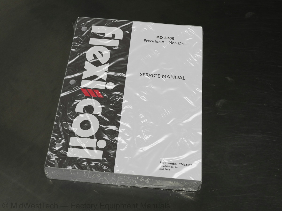
New Holland Flexicoil PD 5700 Precision Air Hoe Drill Service Manual
536 pages · Publication 87492432
Added to your cart. View cart
- Models
- Flexicoil PD 5700 Precision
- Manual type
- Service Manual
- Pages
- 536
- Publication
- 87492432
- Condition
- Brand new
What's inside
From the manual's own table of contents: 94 topics. See sample pages (PDF, 594 KB)
- PRIMARY HYDRAULIC POWER SYSTEM
- LIGHTING SYSTEM
- ELECTRONIC SYSTEM
- FAULT CODES
- AXLES, BRAKES AND STEERING
- FRONT AXLE
- WHEELS AND TRACKS Wheels
- FRAME AND CAB
- FRAME Primary frame
- FRAME POSITIONING
- TRAVELLING Folding
- FRAME LEVELLING
- FIELD PROCESSING
- SEEDING Mechanical system
- SEEDING Electronic system
- SEEDING Air system
- SOIL PREPARATION Planting
- Advice
- Foreword
- FRAME - Safety signs
- Basic instructions
- Torque
- Torque – Hydraulic Tubes and Fittings
- Dimension
Show all 94 topics
- Weight
- Product identification
- Dynamic description Field Operation
- Hydraulic schema
- Detailed view Pressure Control Valve
- Hydraulic schema Hydraulic Pressure Control Valve
- Detailed view Frame Sequencing Valve
- Hydraulic schema Hydraulic Frame Sequencing Control Valve
- Dynamic description Frame Sequencing Valve
- Service instruction
- Pressure test - Sequencing the Hydraulic System
- Install Cover Plate and Decal
- Remove
- Install
- Overhaul
- Static description
- Component diagram
- Component diagram 01
- Check
- Electrical schematic frame 01 - Circuit description
- Electrical schematic frame 02 - Symbol legend
- Electrical schematic frame 03 - Legends
- Electrical schematic frame 04 - Splices
- Electrical schematic frame 05 - Power
- Electrical schematic frame 06 - Lighting
- Electrical schematic frame 07 - Latch Proximity Sensors
- Electrical schematic frame 08 - Castor and Frame Proximity Sensors
- Electrical schematic frame 09 - Pressure Sensors / Pressure Valves
- Electrical schematic frame 10 - Frame Control Valves
- Electrical schematic frame 11 - CAN BUS / Tow Behind Extension
- Component diagram 01 Connectors X-101 to X-114
- Component diagram 02 Connectors X-115 to X-132
- Component diagram 01 Hoe Drill Harness
- Component diagram 02 TBH Extension Harness
- source
- [Precision Hoe Drill Rate ECU] - 520200-03-+5V, Voltage above normal, or shorted to high source
- [Precision Hoe Drill Rate ECU] - 520200-04-+5V, Voltage below normal, or shorted to low source
- Tire pressure
- Disassemble
- Assemble
- Adjust
- Service instruction Inner Caster
- Service instruction Outer Casters
- Service instruction Center Section Caster
- Service instruction Center Section Rear Wheel
- Service instruction Wing Section Rear Wheel
- Dynamic description
- Dynamic description Manual Mode
- Hydraulic schema Fold / Unfold Sequence
- Alarm
- Overview
- Overhaul Fold-Away Wing Cylinder
- Overhaul Caster Lock Cylinder / Drawtube Latch Cylinder
- Overhaul Center Section Toolbar Frame Cylinder
- Overhaul 10 Foot Toolbar Frame Cylinder (50 Foot Inner and Outer, 60 Foot Outer)
- Overhaul 15 Foot Toolbar Frame Cylinder (60 Foot Inner, 70 Foot Inner and Outer)
- Overhaul Boom Swing Cylinder
- Crimping
- Soldering
- Troubleshooting
- Check Faults
- Check Alarms
- Check Reset
- Check Diagnostics - Monitor
- Check Diagnostics - Frame Position Sensor Status
- Check Diagnostics - See What’s Connected
- Check Diagnostics - Version
- Check Diagnostics - Virtual Terminal
- Replace Press Wheel Hub
- Service instruction Opener Cylinder Service
Inside this manual
Real pages from this service manual (536 pages). Open the sample pages (PDF, 594 KB)

- Specifications, page 24: INTRODUCTION
- Diagram, page 128: HYDRAULIC, PNEUMATIC, ELECTRICAL, ELECTRONIC SYSTEMS - ELECTRONIC SYSTEM
- Troubleshooting, page 168: 520197-03-Internal 8V, Voltage above normal, or shorted to high
- Color page, page 426: FRAME POSITIONING - TRAVELLING Folding
- Color page, page 497: FIELD PROCESSING - SEEDING Electronic system
- Foldout diagram, page 121: HYDRAULIC, PNEUMATIC, ELECTRICAL, ELECTRONIC SYSTEMS - ELECTRONIC SYSTEM
This is a service manual
Here's how it compares to the other manual types.
Service manual
Factory repair procedures and technical information such as specifications, troubleshooting, and wiring and hydraulic diagrams, for the models and systems the manual covers. See What's inside for its topics.
Operator's manual
Safe operation, controls, maintenance schedules, lubrication points, inspections, and basic checks. Repair procedures are in the service manual.
Parts manual
Illustrated diagrams with factory part numbers for identifying components and ordering parts. Repair procedures are in the service manual.
Engine service manuals are sometimes sold separately, since certain machine models were offered with more than one engine option.
What it's used for
Factory manual for in-house farm and construction shop use. Straightforward, complete, and easy to follow. It contains the OEM information dealership service departments and parts counters use to diagnose problems, identify components, and perform maintenance or repairs correctly.
Service shops and owner/operators who repair their own equipment
Identifying correct parts and seeing how assemblies come apart and go back together
Keeping equipment running with less downtime
Factory manual, 536 pages
Quantity one is the manual described above.
Fast free USA shipping
Ships in 1 business day.
60-day returns
Free if the mistake is ours. A manual ordered in error must come back unopened in its shrink-wrap; you pay return shipping and a 20% restocking fee applies. Return policy
Binder not included
Manuals over about 300 pages may need a standard 3-ring binder, which you can buy locally to keep the pages organized for shop use.
Questions about model, serial number, engine coverage or contents? Contact us before purchasing and we'll help confirm it's the right manual. Please verify the manual type, machine model, serial number range and engine coverage before purchasing: manuals ordered in error carry a 20% restocking fee (return policy).