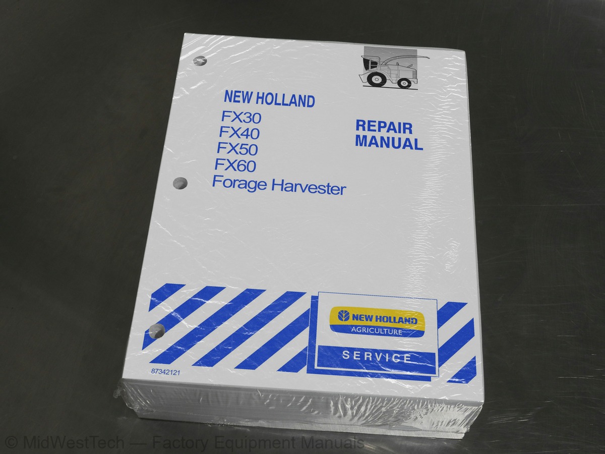
New Holland FX30, FX40, FX50, FX60 Forage Harvester Service Manual
1,097 pages · Publication 87342121
Added to your cart. View cart
What's inside
From the manual's own table of contents: 261 sections, 515 entries. See sample pages (PDF, 763 KB)
General instructions7 topics
- Shimming
- Rotating shaft seals
- O--ring seals
- Sealing compounds
- Bearings
- Cotter pins
- Protecting the electronic / electrical systems during charging or welding
Safety rules7 topics
- General guidelines
- Start-up
- Engine
- Electrical system
- Hydraulic systems
- Wheels and Tyres
- Removal and Re-fitting
Show all 261 sections
Walk around the engine5 topics
- Left Side View
- Right Side View
- Front View
- Rear View
- Top View
Oil filter5 topics
- External Coil
- Upstream Mount
- Filter Septum
- Downstream Mount
- Structural Parts
Electronically controlled injection system1 topic
- Electronic Control Unit
Pump injector3 topics
- Filling Stage
- Injection Stage
- Flow-back Stage
Plan of tightening sequence7 topics
- Sub--Cranckcase
- Cylinder head
- Exhaust manifold
- Turbocharger
- Heat exchanger
- Engine oil sump
- Rocker arm cover
Mechanical troubleshooting1 topic
- Preliminary conditions
Op. 10 001 54 Engine -- Disassembly – Assembly1 topic
- General notes
Selecting main and big end bearing shells11 topics
- Main journals
- Crankpins
- Selecting small end bearings (pins with nominal diameter)
- Selecting the main bearing shells (pins with nominal diameter)
- Selecting the main bearing shells (ground pins)
- Selecting the big end bearing shells (pins with nominal diameter)
- Selecting the big end bearing shells (ground pins)
- Checking main journal assembly clearance
- Tightening sequence of the screws fixing the sub--crankcase under the crankcase
- Remove the sub--crankcase
- Checking crankshaft end float
Main components of the ms6.2 edc system5 topics
- Pump injector
- Operation
- Filling phase
- Injection phase
- Pressure reduction phase
Control unit operation13 topics
- Fuel batching
- Flow--rate correction depending on water temperature
- Flow--rate correction to avoid noises, fumes or overloads
- De--rating
- Electronic injection spark advance check
- Speed regulator
- Engine start--up
- Cold start--up
- Hot start--up
- Run Up
- After Run
- Cylinder Balancing
- Synchronisation search
Preliminary appraisal of data to make the selection2 topics
- Selection of main half-bearings (rectified pins)
- Selection of connecting rod half-bearings (rectified pins)
Cutterhead drive pulley carrier2 topics
- Cutterhead reverse drive motor coupling
- Cutterhead drive pulley shaft
Main drive gearbox -- Remove2 topics
- Battery box -- Remove
- Fuel reservoir -- Remove
Main drive gearbox -- Disassemble / Assemble11 topics
- Splitting the main drive gearbox
- Lower gearbox half -- Disassembly / assembly
- Disassembly
- Assembly
- Intermediate gear assembly
- Hydro gear assembly
- Upper gearbox half -- Disassembly / assembly
- Main hydraulic clutch -- Remove
- Output shaft -- Remove / Install
- Main clutch -- Install
- Connecting the two gearbox halves together
Main clutch -- Overhaul3 topics
- Pressure hose -- Remove / install
- Clutch plates -- Replace
- Clutch seals -- Replace
Main drive gearbox -- Remove / Install4 topics
- Lower gearbox half -- Disassemble / Assemble
- Disassemble
- Assemble
- Main drive gearbox -- Assemble
Disassembly of traction gearbox7 topics
- General
- Removal of selector forks and shifter shafts
- Removal of drive shaft
- Removal of the countershaft
- Removal of transmission main shaft
- Removal of the half--shaft from the differential
- Removal of the differential
Assembly of traction gearbox8 topics
- Assembly of the differential
- Assembly of the half--shafts of the differential
- Assembly of transmission main shaft
- Assembly of the countershaft
- Assembly of the drive shaft
- Assembly of selector shafts and forks
- Calculation of shims to be installed on the shafts
- Assembly of the cover
Tightening torques1 topic
- Self--made tools
4WD gearbox -- Disassembly4 topics
- Intermediate shaft
- Input shaft
- Output shaft and clutch
- Clutch cylinder
4WD gearbox -- Assembly6 topics
- Output shaft and clutch -- pre assembly
- Input shaft -- pre assembly
- Intermediate shaft -- installation
- Input shaft -- installation
- Cover -- installation
- Clutch pre--assembly -- installation
Final drives -- Disassembly1 topic
- Output shaft
Final drives -- Assembly3 topics
- End play adjustment
- Preload adjustment
- Chapter 2 -- Final drives FX40--50
Wheel bolt - Replacement2 topics
- Disassembly
- Assembly
Hydrostatic circuit and components1 topic
- Circuit
Hydrostatic Pump6 topics
- Pump operation
- Pump characteristics
- Multifunction valve
- Servo Valve
- System in Neutral
- Servo Solenoid Valve Energized
Hydrostatic Motor2 topics
- Fixed Displacement Motors
- Drive Motor Characteristics
Brake system1 topic
- Road Mode
Replacement of the brake linings2 topics
- Removal
- Installation
Bleeding the brakes3 topics
- Bleeding the left--hand side circuit
- Bleeding the connection pipe between the two main cylinders
- Bleeding the right--hand side circuit
Disassembly and assembly of brake shoes and discs4 topics
- Disassembly of brake shoes
- Disassembly of brake discs
- Assembly of brake discs
- Assembly of brake shoes
Op. 35.000 Torque tables for hydraulic components6 topics
- Union nuts
- Ferrules
- Metric fittings
- Unions
- Connections
- Swivel nut with ball-type nipple
Disassembly of the pump group4 topics
- Removal of the triple pump from the hydrostatic pump
- Splitting of the triple pump
- Assembly of the pump group
- Installation of the pump group to the hydrostatic pump
Op. 35.000 Circuit diagrams1 topic
- Work Hydraulics -- Attachment height control
Non--return valve1 topic
- Function
Op. 35.304 Work hydraulics pump1 topic
- Specifications
Op. 35.410 Attachment height control valve (EMR)5 topics
- Neutral position
- Attachment lifting position
- Attachment lowering position
- Pressure relief valve h
- Emergency hand buttons
Attachment compensation valve3 topics
- Transport mode
- Compensation mode
- Stubble height mode
Hydropneumatic accumulators1 topic
- Filling
Op. 35.000 Circuit diagrams -- Base unit1 topic
- Repair of control valves
Load sensing valve1 topic
- System in neutral
Spout lift cylinder2 topics
- Cylinder disassembly and assembly
- Reinstallation of spout lift cylinder
Steering valve1 topic
- Special tools
Steering cylinders2 topics
- Disassembly and assembly
- Toe--in adjustment, steering ball joints, steering wheel stops
Op.35.300 Low pressure hydraulic reservoir4 topics
- Oil and Filter change procedure
- Oil pressure check procedure
- Filling the system when (re)installing the low pressure pump
- Filling the system after (re)installing the main drive transfer gearbox
Air conditioning circuit8 topics
- Components
- Refrigerant
- Compressor
- Compressor clutch
- Circuit parameters
- Low pressure switch
- High pressure switch
- Filter--drier
Op. 50.200 Compressor clutch replacement2 topics
- Clutch removal
- Clutch installation
General information6 topics
- Wires
- Color code
- Wire identification
- Fuses
- Symbols
- Relays
Connectors1 topic
- Wiring diagrams FX NA
General layout electronic system2 topics
- Electronic components
- Conclusion
Electronic system layout8 topics
- Input
- Output
- Analog signals (from input or to output)
- Digital Information
- Interfaces
- Software
- Calibrations
- Additional info
Can spy6 topics
- Decimal and hexadecimal counting
- Decimal
- Hexadecimal
- How to use the CAN Identifiers
- How to Enter CAN--SPY
- in practice
Error codes messages1 topic
- Wiring checking procedure
Machine calibration with EST tool5 topics
- Configuration Item Selection screen
- Maximum Handle position calibration
- Minimum forward pump current calibration
- Minimum reverse pump current calibration
- Vehicle Configuration
Attachment height control error messages1 topic
- Error reports
Metal detector roll3 topics
- Metal detector components -- D./A
- Disassembly
- Assembly
Upper feed rolls -- R./I4 topics
- Before removal
- Removal of the upper feed rolls as a complete assembly
- Removal of the upper feed rolls as separate components
- Replacing wear plates on the upper feed rolls frame
Hydroloc gearbox -- D./A8 topics
- Alternative drive shaft
- Transfer shaft
- Upper feed rolls drive shaft
- Selector shaft
- Smooth roll drive shaft
- Metal detector roll drive shaft
- Reinstall the alternative drive shaft
- Install seals and covers
Attachments drive gearbox -- D./A4 topics
- Idler shaft
- Transfer shaft
- Attachment drive shaft
- Idler shaft -- Re--installation
Upper feed rolls drive gearbox -- D./A8 topics
- Upper feed rolls drive shaft
- Front upper feed roll drive shaft
- Rear upper feed roll drive shaft
- Re--install the upper feed rolls drive shaft
- Seals and cover
- Splitting of components
- Rotor and bearings -- R./I
- Shearbar -- R./I
Shearbar support -- R./I1 topic
- Cutterhead gearbox -- R./I
Cutterhead gearbox -- D./A11 topics
- Oil cooler -- D./A
- Gearbox -- Disassembly
- Input shaft
- Output shaft
- Gearbox -- Assembly
- Input shaft
- Output shaft
- Backlash
- Inspection between cutterhead and blower
- Blower -- R./I
- Blower gearbox -- R./I
Blower gearbox -- D./A1 topic
- Adjusting the shimming
Inside this manual
Real pages from this service manual (1,097 pages). Open the sample pages (PDF, 763 KB)

- Specifications, page 46: GENERAL INFORMATION
- Diagram, page 638: SECTION 55 -- ELECTRICAL SYSTEM -- CHAPTER 2
- Troubleshooting, page 814: SECTION 55 -- ELECTRICAL SYSTEM -- CHAPTER 6
- Color page, page 477: SECTION 29 -- HYDROSTATIC SYSTEM
- Foldout diagram: SECTION 55 -- ELECTRICAL SYSTEM -- CHAPTER 2
Other manuals for this machine
Save 10% on 2 manuals, 15% on 3 or more. Other manuals for the FX30, FX40, FX50 are listed below. Editions cover different serial number ranges: check the serial coverage and tick only the ones that match your machine.
Added to your cart. View cart
This is a service manual
Here's how it compares to the other manual types.
Service manual
Factory repair procedures and technical information such as specifications, troubleshooting, and wiring and hydraulic diagrams, for the models and systems the manual covers. See What's inside for its topics.
Operator's manual
Safe operation, controls, maintenance schedules, lubrication points, inspections, and basic checks. Repair procedures are in the service manual.
Parts manual
Illustrated diagrams with factory part numbers for identifying components and ordering parts. Repair procedures are in the service manual.
Engine service manuals are sometimes sold separately, since certain machine models were offered with more than one engine option.
What it's used for
Factory manual for in-house farm and construction shop use. Straightforward, complete, and easy to follow. It contains the OEM information dealership service departments and parts counters use to diagnose problems, identify components, and perform maintenance or repairs correctly.
Service shops and owner/operators who repair their own equipment
Identifying correct parts and seeing how assemblies come apart and go back together
Keeping equipment running with less downtime
Factory manual, 1,097 pages
Quantity one is the manual described above.
Fast free USA shipping
Ships in 1 business day.
60-day returns
Free if the mistake is ours. A manual ordered in error must come back unopened in its shrink-wrap; you pay return shipping and a 20% restocking fee applies. Return policy
Binder not included
Manuals over about 300 pages may need a standard 3-ring binder, which you can buy locally to keep the pages organized for shop use.
Questions about model, serial number, engine coverage or contents? Contact us before purchasing and we'll help confirm it's the right manual. Please verify the manual type, machine model, serial number range and engine coverage before purchasing: manuals ordered in error carry a 20% restocking fee (return policy).