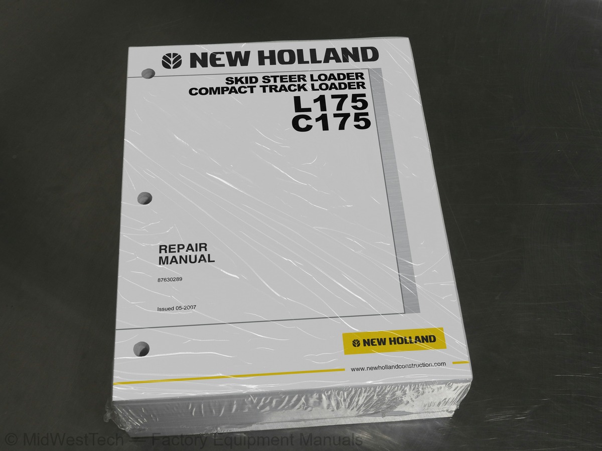
New Holland L175, C175 Skid Steer Compact Track Loader Service Manual
988 pages · Publication 87630289NA
Added to your cart. View cart
What's inside
From the manual's own table of contents: 13 sections, 277 entries. See sample pages (PDF, 969 KB)
SECTION 00 – GENERAL INFORMATION27 topics
- Introduction
- About Improvements
- Company Policy
- Parts and Accessories
- Model Codes
- Precautionary Statements
- Safety Precaution Information
- General Safety Information
- Machine Model and Serial Number Location
- Engine Model and Serial Number Location
- Hardware Torque Specifications
- Installation of Adjustable Fittings in Straight Thread O Ring Bosses
- Standard Torque Data for Hydraulic Tubes and Fittings
- Pipe Thread Fitting Torque
- Lubricants and Coolants
- Sealants
- Properly Support a Raised Machine
- Properly Support Boom on Boom Lock Pins
- Raising Boom Without Hydraulic Oil Flow
- Raising Boom Without Battery Voltage (12V)
- Reattaching Cylinders After Repair with Boom Resting on Boom Lock Pins
- Major Unit Overhaul
- Cab and Boom Tilt Procedure
- Craning the Skid Steer
- Specifications
- Dimensions
- Cab and Boom Tilt Procedure (Cab Upgrade Machines Only)
SECTION 10 – ENGINE31 topics
- General Engine Information
- General Description
- Engine Component Descriptions
- Turbocharger Lubrication
- Safety Precautions
- General Engine Specifications
- Troubleshooting
- L175 - Excessive Oil Consumption
- Specifications - Service Standards
- Torque Specifications
- Engine Components Electrical Diagram
- Engine Removal
- Engine Disassembly Sequence
- Engine Component Maintenance
- Valve Seat
- Cylinder Block
- Piston and Piston Rings
- Connecting Rod
- Bearing Holder
- Front Crankshaft Bearing (Bushing)
- Crankshaft
- Flywheel and Ring Gear
- Camshaft Assembly
- Camshaft Gear and Bearing Assembly
- Timing Gear
- Oil Pump
- Oil Filter
- Water Pump Assembly and Thermostat Housing
- Thermostat
- Governor
- Governor Operation
SECTION 27 - TRACKS19 topics
- 27 000 Specifications
- Special Torques
- Wheel Hub Housing - Remove
- Wheel Hub Housing - Install
- Drive Sprocket - Remove
- Drive Sprocket - Install
- Rubber Track - Remove
- Rubber Track - Install
- Rubber Track - Tension Adjust
- Track Tension Mechanism - Remove
- Track Tension Mechanism - Install
- Track Roller - Remove
- Track Roller - Install
- Idler Wheel - Remove
- Idler Wheel - Install
- Track Drive Motor - Remove
- Track Drive Motor - Install
- Track Drive Motor - Disassembly
- Track Drive Motor - Assembly
SECTION 29- HYDROSTATIC TRANSMISSION29 topics
- General Information
- Operation
- Hydrostatic Drive System Testing
- Hydrostatic System Oil Flow
- Hydrostatic Charge System Pressure Test
- Hydrostatic Pump Case Drain Test
- Hydrostatic Pump High Pressure Test
- Hydrostatic Pump Efficiency Test
- Hydrostatic Motor Case Drain Test
- Hydrostatic Motor Efficiency Test
- Hydraulic, Hydrostatic System Air Ingress Test
- Hydrostatic Pumps
- Hydrostatic Pump Removal
- Hydrostatic Pump Disassembly
- Hydrostatic Pump Parts Inspection
- Hydrostatic Pump Reassembly
- Hydraulic System Pump Installation (Without High Flow)
- Hydraulic System Pump/High Flow Pump Installation
- Hydrostatic Pump Reinstallation
- Hydrostatic Motor
- Hydrostatic Motor Removal
- Hydrostatic Motor Disassembly
- Hydrostatic Motor Parts Inspection
- Hydrostatic Motor Reassembly
- Hydrostatic Motor Reinstallation
- Hydraulic System Cleaning Procedure
- Start-up Procedure After Rebuild (After Pump or Motor Replacement)
- Charge Check Valve
- Charge Check Valve Removal and Replacement
SECTION 33 - BRAKES AND CONTROLS8 topics
- 33 110 Parking Brake Removal
- Parking Br ake Reinstallation
- Parking Brake Disassembly
- Parking Brake Reassembly
- Troubleshooting - Parking Brake Button - Testing
- Troubleshooting - Electrical Solenoid - Testing
- Brake Valve - Illustration
- Brake / Two- Speed Valve - Illustration
SECTION 37 – TOWING HOOKS AND BALLASTING9 topics
- Rear Counterweights
- Rear Counterweight Support Removal
- ROPS
- ROPS Frame
- ROPS Removal
- ROPS Reinstallation
- Labor Guide
- ROPS Removal (Cab Upgrade Machines Only)
- ROPS Installation (Cab Upgrade Machines Only)
SECTION 44 - AXLES AND WHEELS13 topics
- 44 100 General Information
- Testing
- 44 106 10 Axle Housing Assembly Removal
- 44 106 16 Axle Disassemby
- Axle Parts Inspection
- Axle Reassembly
- Axle Housing Reinstallation
- Final Drive
- Drive Chain and Sprocket Removal
- Final Drive Parts Inspection
- Final Drive Reassemby
- Drive Chain - Tension Adjust
- Tire/Wheels
SECTION 50 - CAB CLIMATE CONTROL22 topics
- 50 100 Heater/Defroster (Cab)
- Air Conditioning System Special Tools
- Air Conditioning System General Specifications
- Air Conditioning System Discharging and Evacuate and Recovery
- Air Conditioning System Charging
- Compressor Removal
- Compressor Installation
- Compressor Oil Level Check
- Compressor Belt Measure and Tension Adjust
- Compressor Magnetic Clutch Disassemble
- Compressor Magnetic Clutch Assembly
- Air Conditioning System Removal
- Air Condit ioning System Installation
- Air Conditioning System Condenser Removal
- Air Conditioning System Condenser Installation
- Air Conditioning System Evaporator Removal
- Air Conditioning System Evaporator Installation
- Receiver/Drier Removal and Installation
- Air Conditioning System Visual Inspection and Troubleshooting
- Air Conditioning System Testing
- Air Conditioning System Leakage Test
- Air Conditioning System Problem Solving
SECTION 55 - ELECTRICAL SYSTEM35 topics
- 55 000 General Electrical Information
- Definition of Terms
- Adapting Attachments Requiring 12V Electrical Power
- Wire Identification and Circuit Diagram Legend
- Electrical Diagram - Starting System
- Electrical Diagram -Safety Interlock and Fuel Supply System
- Electrical Diagram - Instrument Cluster Monitoring System
- Electrical Diagram - Standard Lamps
- Electrical Diagram - Loader Arm Auxiliary Electrical Control Box (Optional)
- Electrical Diagram - Loader Arm Auxiliary Electric Power Controls (Optional)
- Electrical Diagram - Flasher and Turn Signals North America Electrical
- Electrical Diagram - Main Electrical European On-Road Regulations
- Electrical Diagram - Boom/Rear Electrical European On-Road Regulations
- Electrical Diagram - Right-Hand Handle (Option) Electrical Multifunction Adaptation
- Electrical Diagram - Left-Hand Handle (Options)
- Electrical Diagram - Right-Hand Handle (Options)
- Electrical Diagram - Glow Plugs
- Electrical Diagram - Rotating Beacon (Optional)
- Electrical Diagram - Two Speed (Optional)
- Electrical Diagram - Horn (Optional)
- Electrical Diagram - Accessory Outlet (Optional)
- Electrical Diagram - Back-up Alarm (Optional)
- Electrical Diagram - Wiper/Washer (Optional)
- Electrical Diagram - Auxiliary Hydraulics (Optional)
- Electrical Diagram - High Flow (Optional)
- Electrical Diagram - Hydraulic Coupler (Optional)
- Electrical Diagram - Heating and Air Conditioning (Optional)
- Electrical Diagram - Pilot Hydraulic Controls
- Electrical Diagram - Ground Connections
- Wire Identification and Circuit Diagram Legend (Cab Upgrade Machines)
- Electrical Diagram - Starting System (Cab Upgrade Machines)
- Electrical Diagram - Power Distribution (Cab Upgrade Machines)
- Electrical Diagram - Instrument Cluster Monitoring System (Cab Upgrade Machines)
- Electrical Diagram - Standard Lamps (Cab Upgrade Machines)
- (Cab Upgrade Machines)
SECTION 82 – FRONT LOADER (BOOM AND MOUNTING PLATE)27 topics
- Buckets
- Boom Lock Pins and Linkage
- Boom
- Attachment Mounting Plate
- Boom and Cylinder Pivot Pins
- Boom and Cylinder Pivot Pin Location and Machine Usage
- Boom and Cylinder Pivot Pins Size
- Pallet Fork
- Utility Fork
- Bucket Cutting Edge (Replacement)
- Bucket Latch Plate Installation Procedure
- Dirt Tooth Kit Installation
- Bucket Tooth Spacing
- Boom Lock Pin/Linkage
- Boom Lock Pin/Linkage Removal
- Boom Lock Pin/Linkage Reinstallation
- Boom, Upper and Lower Link
- Boom, Upper and Lower Link Removal
- Front Boom Mounting Plate Pivot Hub Replacement
- Boom, Upper and Lower Link Reinstallation
- Attachment Mounting Plate Removal
- Repair/Rebuild Mounting Plate
- Latch Lever and Pin Removal/Repair
- Attachment Mounting Plate Parts Inspection
- Checking Procedure for Buckets and Attachments
- Checking Procedure
- Checking the Loader Faceplate
SECTION 88 – ACCESSORIES17 topics
- Hydraulic System Compatibility
- Arm Pads For Cab Side Panels
- Armrests for Deluxe Seat
- Forearm Rests
- Back-up Alarm
- Block Heater (Engine)
- Electric Power Supply (12 Volt, 15 Amp)
- Exhaust (Engine)
- Aspirator Precleaner Muffler
- High Flow Hydraulics
- High Flow Hydraulics Troubleshooting
- High Flow Hydraulics Component Replacement
- Horn
- Shoulder Belt (Seat)
- Slow-moving Vehicle (SMV) Sign Kit
- Warning Light (Rotary Beacon)
- Warning Lights (Four-way Flashers/Turn Signal/Horn)
SECTION 90 – PLATFORM, CAB, BODYWORK, AND DECALS27 topics
- Seat and Seat Pan Support
- Cab Inner Shell
- Seat Removal
- Seat Pan Support Removal
- Seat, Switch and Pan Reinstallation
- Cab Inner Shell Removal
- Cab Inner Shell Reinstallation
- Safety Decals
- Raising Boom Without Battery Voltage (12V
- Special Tools
- Parking Brake Reinstallation
- Brake / Two-Speed Valve - Illustration
- Air Conditioning Sytem Special Tools
- Air Conditioning Sytem General Specifications
- Air Conditioning Sytem Discharging and Evacuate and Recovery
- Air Conditioning Sytem Charging
- Air Conditioning Sytem Removal
- Air Conditioning Sytem Installation
- Air Conditioning Sytem Condenser Removal
- Air Conditioning Sytem Condenser Installation
- Air Conditioning Sytem Evaporator Removal
- Air Conditioning Sytem Evaporator Installation
- Air Conditioning Sytem Visual Inspection and Troubleshooting
- Air Conditioning Sytem Testing
- Air Conditioning Sytem Leakage Test
- Air Conditioning Sytem Problem Solving
- Electrical Diagram - Power Distribution
Inside this manual
Real pages from this service manual (964 pages). Open the sample pages (PDF, 968 KB)

- Specifications, page 83: SECTION 10 - ENGINE
- Troubleshooting, page 167: SECTION 10 - ENGINE
- Diagram, page 601: SECTION 39 - FRAMES
- Color page: SECTION 29- HYDROSTATIC TRANSMISSION
- Color page: SECTION 29- HYDROSTATIC TRANSMISSION
- Foldout diagram: POS-CBL
Other manuals for this machine
Save 10% on 2 manuals, 15% on 3 or more. Other manuals for the L175, C175 are listed below. Editions cover different serial number ranges: check the serial coverage and tick only the ones that match your machine.
Added to your cart. View cart
This is a service manual
Here's how it compares to the other manual types.
Service manual
Factory repair procedures and technical information such as specifications, troubleshooting, and wiring and hydraulic diagrams, for the models and systems the manual covers. See What's inside for its topics.
Operator's manual
Safe operation, controls, maintenance schedules, lubrication points, inspections, and basic checks. Repair procedures are in the service manual.
Parts manual
Illustrated diagrams with factory part numbers for identifying components and ordering parts. Repair procedures are in the service manual.
Engine service manuals are sometimes sold separately, since certain machine models were offered with more than one engine option.
What it's used for
Factory manual for in-house farm and construction shop use. Straightforward, complete, and easy to follow. It contains the OEM information dealership service departments and parts counters use to diagnose problems, identify components, and perform maintenance or repairs correctly.
Service shops and owner/operators who repair their own equipment
Identifying correct parts and seeing how assemblies come apart and go back together
Keeping equipment running with less downtime
Factory manual, 988 pages
Quantity one is the manual described above.
Fast free USA shipping
Ships in 1 business day.
60-day returns
Free if the mistake is ours. A manual ordered in error must come back unopened in its shrink-wrap; you pay return shipping and a 20% restocking fee applies. Return policy
Binder not included
Manuals over about 300 pages may need a standard 3-ring binder, which you can buy locally to keep the pages organized for shop use.
Questions about model, serial number, engine coverage or contents? Contact us before purchasing and we'll help confirm it's the right manual. Please verify the manual type, machine model, serial number range and engine coverage before purchasing: manuals ordered in error carry a 20% restocking fee (return policy).