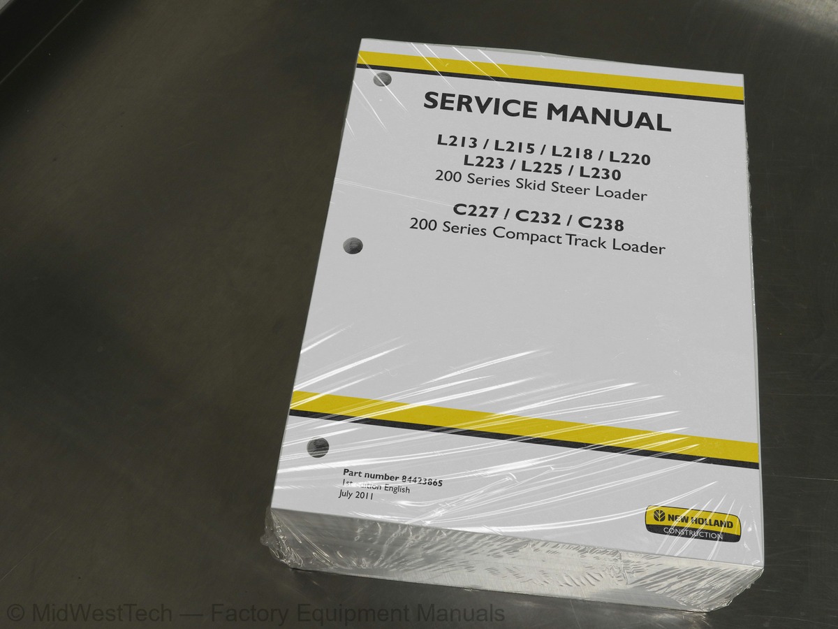
New Holland L213, L215, L218, L220, L223, L225, L230, C227, C232, C238 Skid Steer Compact Track Loader Service Manual
1,742 pages · Publication 84423865
Added to your cart. View cart
What's inside
From the manual's own table of contents: 229 topics. See sample pages (PDF, 766 KB)
- PRIMARY HYDRAULIC POWER SYSTEM
- SECONDARY HYDRAULIC POWER SYSTEM
- HYDRAULIC COMMAND SYSTEM
- HIGH-FLOW HYDRAULIC POWER SYSTEM
- ELECTRICAL POWER SYSTEM
- LIGHTING SYSTEM
- ELECTRONIC SYSTEM
- FAULT CODES
- ENGINE AND PTO IN
- ENGINE
- FUEL AND INJECTION SYSTEM
- AIR INTAKE SYSTEM
- ENGINE COOLANT SYSTEM
- STARTING SYSTEM
- TRANSMISSION, DRIVE AND PTO OUT
- TRANSMISSION Hydrostatic
- AXLES, BRAKES AND STEERING
- Final drive
- Final drive Hydraulic drive
- STEERING Mechanical
- PARKING BRAKE Hydraulic
- WHEELS AND TRACKS Tracks
- WHEELS AND TRACKS Wheels
- FRAME AND CAB
Show all 229 topics
- FRAME Primary frame
- SHIELD
- Foreword - Ecology and the environment
- Safety rules
- Safety rules - Personal safety
- Basic instructions - How To Use and Navigate Through This Manual
- Basic instructions - Important notice regarding equipment servicing
- Basic instructions - Shop and Assembly
- Torque - Minimum tightening torques for normal assembly
- Torque - Standard torque data for hydraulics
- General specification - Biodiesel Fuels
- General specification - General Welding
- General specification for the 24.9cc Gear Pump
- General specification of the 24.9cc Gear pump with high flow 12.5cc pump
- General specification of the 34.1cc gear pump
- General specification of the 20.4cc gear pump
- General specification for 34.1cc Front pump with rear pump 23.0cc
- General specification for the 34.1cc Gear pump with high flow 12.5cc
- General specification for the 34.1cc Gear pump with high flow 18.3cc
- General specification Hydraulic oil return filter
- General specification Hydraulic oil supply strainer
- General specification of the Ride / Glide Control Valve
- General specification of the EH Control Loader Valve for all models
- General specification Mechanical Hand Control Loader valve on all models
- General specification of Mechanical Foot Control Loader Valve
- General specification of the EH and Mechanical boom override valve on all models
- General specification of Secondary Auxiliary Valve
- General specification High Flow Valve
- Overview of Contaminates
- Overview EH Drive Pattern Selector Switch
- General specification Main Power Distribution Fuse Block 1
- General specification Accessory Power Distribution
- General specification Resistance to Temperature Conversion Chart
- Component identification Relay Index
- Component identification Sensor Index
- Component identification Motor Index
- Component identification Solenoid Index
- Component identification Diode Index
- Component identification Lighting Index
- Component identification Miscellaneous Index
- Component identification Switch Index
- Overview
- Overview Potentiometers
- Overview Switches
- Overview Resistance devices
- Overview Solenoids
- Overview Pulse width modulation (PWM) solenoid valves
- Component identification Fuse Index
- Relay - Overview
- Fuse - Overview
- Testing Lamp Selector Switch
- Testing Flasher Module
- Testing Hazard Lamp Switch
- Testing Turn Signal Switch
- General specification Instrument Cluster pin information
- Overview EST overview
- H1 - Calibration procedures Calibration Requirements
- H1 - Calibration procedures Calibration Procedure Troubleshooting
- H1 - Calibration procedures Joystick Calibration
- H1 - Calibration procedures Ground Drive Calibration
- H1 - Calibration procedures Throttle Calibration
- H1 - Calibration procedures Loader Calibration
- H1 - Calibration procedures Loader Start Pressure Calibration
- 111-EGR potentiometer valve could not be completely opened
- 112-EGR potentiometer valve could not be completely closed
- 119-Engine crank signal present for 300 seconds
- 126-Battery voltage fault
- 131-Coolant temperature sensor fault
- 134-Intake air pressure sensor fault
- 141-Engine speed sensor fault
- 186-EGR valve position sensor fault
- 189-EGR valve position driver fault
- 1E5-Sensor voltage supply fault
- 2E5-Sensor ground fault
- 1002- Engine Coolant Temperature Sender - Over Temperature >110° C
- 1004- Hydraulic Filter Restriction Switch - Hydraulic Filter Restricted
- 1009- Hydraulic Oil Temperature Sender - Over Temperature >210° F
- 1014- Cluster Battery Monitor - Over Voltage > 16.5 volts
- 1015-Cluster Battery Monitor - Under Voltage < 11.5 volts
- 1041- RPM Monitoring - Over Speed
- 1045- Fuel Level Sensor - OC
- 1201- Hydraulic Filter Restriction Switch - OC
- 1202- RPM Monitoring - Over Speed (Max)
- 1203- RPM Monitoring - Open Circuit / STG / STP
- 1204- Start Sequence - Key Switch State - Engine Running Plausability Fault
- Remove
- Install
- General specification Resistance Fuel Bar Conversion
- Adjust
- Level sensor - Remove Fuel Level Sender
- Level sensor - Install Fuel Level Sender
- Drain fluid
- Filling
- General specification 35cc EH Hydrostatic pump, used with small and medium frame models
- General specification 46cc EH Hydrostatic pump
- General specification 46cc EHF Hydrostatic pump, used with large frame models
- frame models
- General specification 46cc Hydrostatic tandem pump, used with medium and large frame models
- General specification 53cc hydrostatic pump, used with large frame models
- General specification 46cc Hydrostatic tandem pump, used with large frame models
- General specification for mechanical 470cc single speed motor on medium and large frames
- General specification for 325cc 2 speed motor on medium frames
- General specification for EH and Mechanical 470cc 2 speed motor on medium and large frames
- General specification for track drive 2 speed motor on medium and large frames
- Overview Hydrostatic pump model identification
- Overview 2 Speed Switch
- Overview Self Level
- Overview Glide Ride control
- Testing Glide Ride Control Solenoid and Switch
- Testing 2 Speed Switch and Indicator
- Testing Self Level Switch and Valve
- General specification of the EH track brake valve on medium and large frame
- General specification of the EH 2 speed brake valve on medium and large frame
- General specification 2speed brake valve
- General specification of the EH single speed brake valve on small frame
- Overview Park Brake
- Remove Brake valve solenoid for models with single speed
- Install Brake valve solenoid for models with single speed
- Remove 2speed solenoid
- Install 2speed solenoid
- Remove Loader pilot interlock valve solenoid
- Install Loader pilot interlock valve solenoid
- brake valve
- Tension adjust
- USER CONTROLS AND SEAT
- USER CONTROLS AND SEAT Operator seat
- USER PLATFORM
- ENVIRONMENT CONTROL Heating system
- ENVIRONMENT CONTROL Air-conditioning system
- SAFETY SECURITY ACCESSORIES Safety
- Left - Remove Left hand side console
- Left - Install Left hand side console
- Digital instrument cluster - Remove
- Digital instrument cluster - Install
- Remove Right hand side console
- Install Right hand side console
- Overview Door Switch - Overview
- Tilt cab, secure the lift arm in the raised position
- Lower
- Testing Accessory Power Outlet
- Testing Door Switch
- General specification
- Overview HVAC System
- Overview HVAC Mechanical
- Overview HVAC Electrical
- Overview HVAC Box
- Discharging
- Charging
- Leakage test
- Evacuate
- Belt - Tension adjust
- Problem solving HVAC
- Testing A/C Compressor
- Testing HVAC Condenser Fan
- LIFTING
- TILTING
- LEVELLING
- SECONDARY FUNCTIONS Hydraulic
- Adjust for direct mechanical foot controls
- General specification of the 60% self level valve on medium and large frame
- General specification of the 48% self level valve on small frame
- General specification of the 50% self level valve on medium frame
- General specification of the 40% self level valve on medium frame
- Remove Self Level Valve Solenoid
- Install Self Level Valve Solenoid
- Remove Self level valve
- Install Self level valve
- Overview High Flow
- Overview Auxiliary Override Control
- Testing 2nd Aux Extend Solenoid
- Testing 2nd Aux Retract Solenoid
- Testing 2nd Aux Hyd Switch
- Testing High Flow Switch
- BOOM Lift
- ARM TOOL ATTACHMENT Tilt
- SINGLE ARM Lift
- SINGLE ARM TOOL ATTACHMENT Tilt
- Overview loader lock control valve
- Remove single lift arm
- Install single lift arm
- Pressure test
- Remove loader valve extend solenoid
- Install Loader Valve Extend Solenoid
- Remove loader valve retract solenoid
- Install loader valve retract solenoid
- Remove bucket valve extend solenoid
- Install Bucket Valve Extend Solenoid
- Remove bucket valve retract solenoid
- Install bucket valve retract solenoid
- Remove proportional auxiliary valve extend solenoid on EH machines
- Install proportional auxiliary valve extend solenoid (EH)
- Remove proportional auxiliary valve retract solenoid (Mechanical)
- Install proportional auxiliary valve retract solenoid (Mechanical)
- DIGGING Non-articulated digging tools
- CARRYING Unarticulated tools
- COUPLING Mechanical coupling
- COUPLING Hydraulic coupling
- Remove - Mechanical
- Install - Mechanical
- Remove - Hydraulic
- Install - Hydraulic
- Exploded view
- Disassemble
- Assemble
- Testing Hydraulic Coupler Switch and Solenoid
Inside this manual
Real pages from this service manual (1,742 pages). Open the sample pages (PDF, 766 KB)
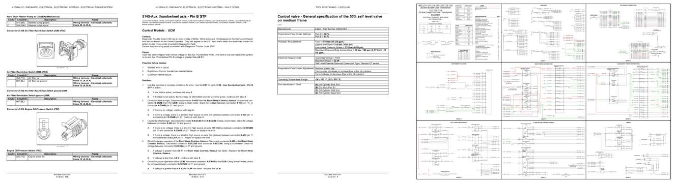
- Diagram, page 306: HYDRAULIC, PNEUMATIC, ELECTRICAL, ELECTRONIC SYSTEMS - ELECTRICAL POWER SYSTEM
- Troubleshooting, page 852: HYDRAULIC, PNEUMATIC, ELECTRICAL, ELECTRONIC SYSTEMS - FAULT CODES
- Specifications, page 1,528: TOOL POSITIONING - LEVELLING
- Foldout diagram (color): GROUNDS
Other manuals for this machine
Save 10% on 2 manuals, 15% on 3 or more. Other manuals are listed below. Editions cover different serial number ranges: check the serial coverage and tick only the ones that match your machine.
Added to your cart. View cart
This is a service manual
Here's how it compares to the other manual types.
Service manual
Factory repair procedures and technical information such as specifications, troubleshooting, and wiring and hydraulic diagrams, for the models and systems the manual covers. See What's inside for its topics.
Operator's manual
Safe operation, controls, maintenance schedules, lubrication points, inspections, and basic checks. Repair procedures are in the service manual.
Parts manual
Illustrated diagrams with factory part numbers for identifying components and ordering parts. Repair procedures are in the service manual.
Engine service manuals are sometimes sold separately, since certain machine models were offered with more than one engine option.
What it's used for
Factory manual for in-house farm and construction shop use. Straightforward, complete, and easy to follow. It contains the OEM information dealership service departments and parts counters use to diagnose problems, identify components, and perform maintenance or repairs correctly.
Service shops and owner/operators who repair their own equipment
Identifying correct parts and seeing how assemblies come apart and go back together
Keeping equipment running with less downtime
Factory manual, 1,742 pages
Quantity one is the manual described above.
Fast free USA shipping
Ships in 1 business day.
60-day returns
Free if the mistake is ours. A manual ordered in error must come back unopened in its shrink-wrap; you pay return shipping and a 20% restocking fee applies. Return policy
Binder not included
Manuals over about 300 pages may need a standard 3-ring binder, which you can buy locally to keep the pages organized for shop use.
Other editions and similar models
Questions about model, serial number, engine coverage or contents? Contact us before purchasing and we'll help confirm it's the right manual. Please verify the manual type, machine model, serial number range and engine coverage before purchasing: manuals ordered in error carry a 20% restocking fee (return policy).