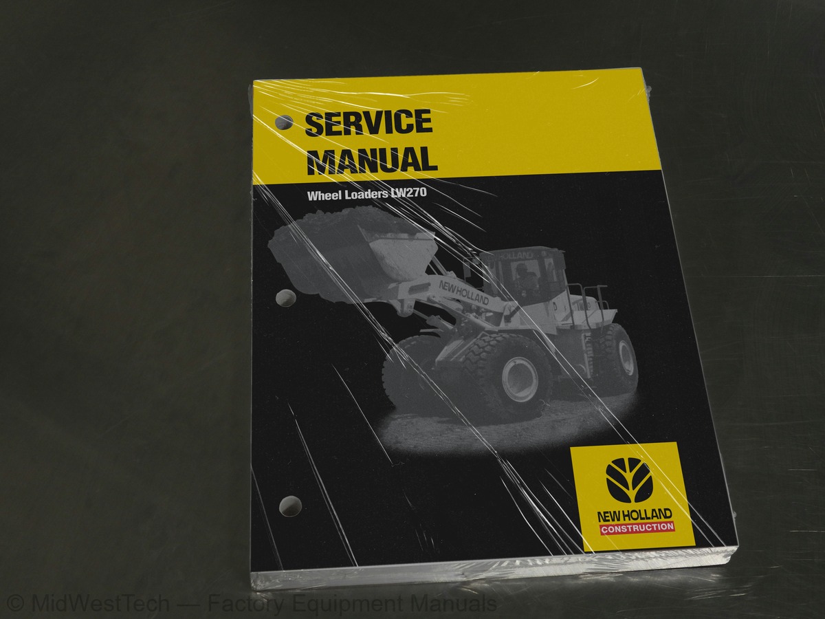
New Holland LW270 Wheel Loader Service Manual
389 pages · Publication 75131020
Added to your cart. View cart
- Models
- LW270
- Manual type
- Service Manual
- Pages
- 389
- Publication
- 75131020
- Condition
- Brand new
What's inside
From the manual's own table of contents: 6 sections, 113 entries. See sample pages (PDF, 380 KB)
ENGINE5 topics
- PARAGRAPH
- IDENTIFICATION DATA
- GENERAL SPECIFICATIONS OF SERIES “M11” ENGINE
- ENGINE SUPPORTS
- DIAGRAMS OF SERIES “M11” ENGINES
TRANSMISSION27 topics
- GENERAL DESCRIPTION
- TORQUE CONVERTER - TRANSMISSION
- TORQUE CONVERTER
- TRANSMISSION - TORQUE CONVERTER PUMP
- TRANSMISSION
- Power train diagram
- Transmission control valve
- AUTOMATIC TRANSMISSION CONTROL SYSTEM
- TRANSMISSION SELECTOR
- OIL CIRCUIT
- DISASSEMBLY TRANSMISSION
- REASSEMBLY TRANSMISSION
- TROUBLESHOOTING GUIDE
- MAINTENANCE REFERENCE VALUES
- TIGHTENING TORQUES
- PROP SHAFTS
- FRONT AND REAR AXLES
- Description of axles
- Description of differential
- Description of final drives
- DISASSEMBLY OF AXLES
- REASSEMBLY OF AXLES
- TROUBLESHOOTINGS
- STANDARD VALUES FOR MAINTENANCE
- TIGHTENING TORQUE VALVE FOR MAIN BOLTS
- WHEELS
- Tires
BRAKES SYSTEM23 topics
- OPERATION
- Operation conditions
- DISC BRAKE
- BRAKE PEDAL VALVE
- Operation of circuit separation valve in the brake group
- BRAKES/POWER SYSTEM PUMP
- PARKING BRAKE CONTROL VALVE
- PARKING BRAKE
- Procedure for manual disengagement
- Operation of discs parking brake
- Disengagement of brake
- OTHER COMPONENTS
- Service brakes accumulator
- Check valve
- HYDRAULIC CONNECTIONS OF BRAKE PEDAL VALVE
- TROUBLE SHOOTING - TESTS
- Test of brakes actuation pressure
- Setting of minimum and maximum accumulators recharge pressure
- Inspection of parking brake engagement
- Inspection of accumulator pre-charge
- Instructions for the pre-charging of the service brakes accumulator
- Air bleeding of brakes system
- Check of brake discs wear
STEERING SYSTEM11 topics
- STEERING GROUP
- STEERING VALVE
- STEERING SYSTEM PUMP
- STEERING VALVE CONTROL LINKAGE
- Linkage installation procedure
- STEERING CYLINDERS
- Removal
- Disassembly and reassembly
- Installation
- EMERGENCY STEERING CIRCUIT
- Components of the emergency steering
BUCKET BOOMS AND FRAME6 topics
- Bucket
- Bucket positioner device
- Boom kick-out setting
- FRAME
- Frame centre pivoting
- BUCKET ABUTTING
ELECTRICAL SYSTEM35 topics
- SAFETY RULES
- GENERAL LAY-OUT OF ELECTRICAL SYSTEM
- LOGIC BOARD AND CAB CONNECTIONS
- Connections - Relays - Timers
- Fuses table
- CAB INSTRUMENTS CLUSTER
- Indicators on instrument cluster
- SWITCH PANEL
- TRANSMISSION CONTROL SELECTOR
- ATC ELECTRONIC UNIT
- CONNECTORS
- COLD START AND LINK FUSES
- STARTER SWITCH
- MAIN SWITCH
- SOLENOID SWITCHES
- PRESSURE SWITCHES-SENSOR-SWITCHES
- ACOUSTIC TRANSDUCERS
- ALTERNATOR
- MACHINE GROUPS ELECTRIC DIAGRAMS
- WINDSCREEN WIPERS AND WASHERS
- HEATER
- GLASSES
- Characteristics
- Disassembly and assembly
- REPAIR
- Cab (removal/installation)
- AIR CONDITIONING UNIT
- Operating istructions
- Technical data
- Service precautions
- Tool connections
- Discharging
- Refrigerant charging
- Leak inspection
- TROUBLESHOOTING
Inside this manual
Real pages from this service manual (389 pages). Open the sample pages (PDF, 379 KB)

- Diagram, page 60: : Clutches
- Repair procedure, page 138: Reassembling cap assembly
- Specifications, page 324: ELECTRICAL SYSTEM
- Color page, page 72: TRANSMISSION
- Foldout diagram (color), page 202: Fig. 3-2 HYDRAULIC BRAKING CIRCUIT SCHEMATIC
Other manuals for this machine
Save 10% on 2 manuals, 15% on 3 or more. Other manuals for the LW270 are listed below. Editions cover different serial number ranges: check the serial coverage and tick only the ones that match your machine.
Added to your cart. View cart
This is a service manual
Here's how it compares to the other manual types.
Service manual
Factory repair procedures and technical information such as specifications, troubleshooting, and wiring and hydraulic diagrams, for the models and systems the manual covers. See What's inside for its topics.
Operator's manual
Safe operation, controls, maintenance schedules, lubrication points, inspections, and basic checks. Repair procedures are in the service manual.
Parts manual
Illustrated diagrams with factory part numbers for identifying components and ordering parts. Repair procedures are in the service manual.
Engine service manuals are sometimes sold separately, since certain machine models were offered with more than one engine option.
What it's used for
Factory manual for in-house farm and construction shop use. Straightforward, complete, and easy to follow. It contains the OEM information dealership service departments and parts counters use to diagnose problems, identify components, and perform maintenance or repairs correctly.
Service shops and owner/operators who repair their own equipment
Identifying correct parts and seeing how assemblies come apart and go back together
Keeping equipment running with less downtime
Factory manual, 389 pages
Quantity one is the manual described above.
Fast free USA shipping
Ships in 1 business day.
60-day returns
Free if the mistake is ours. A manual ordered in error must come back unopened in its shrink-wrap; you pay return shipping and a 20% restocking fee applies. Return policy
Binder not included
Manuals over about 300 pages may need a standard 3-ring binder, which you can buy locally to keep the pages organized for shop use.
Other editions and similar models
Questions about model, serial number, engine coverage or contents? Contact us before purchasing and we'll help confirm it's the right manual. Please verify the manual type, machine model, serial number range and engine coverage before purchasing: manuals ordered in error carry a 20% restocking fee (return policy).