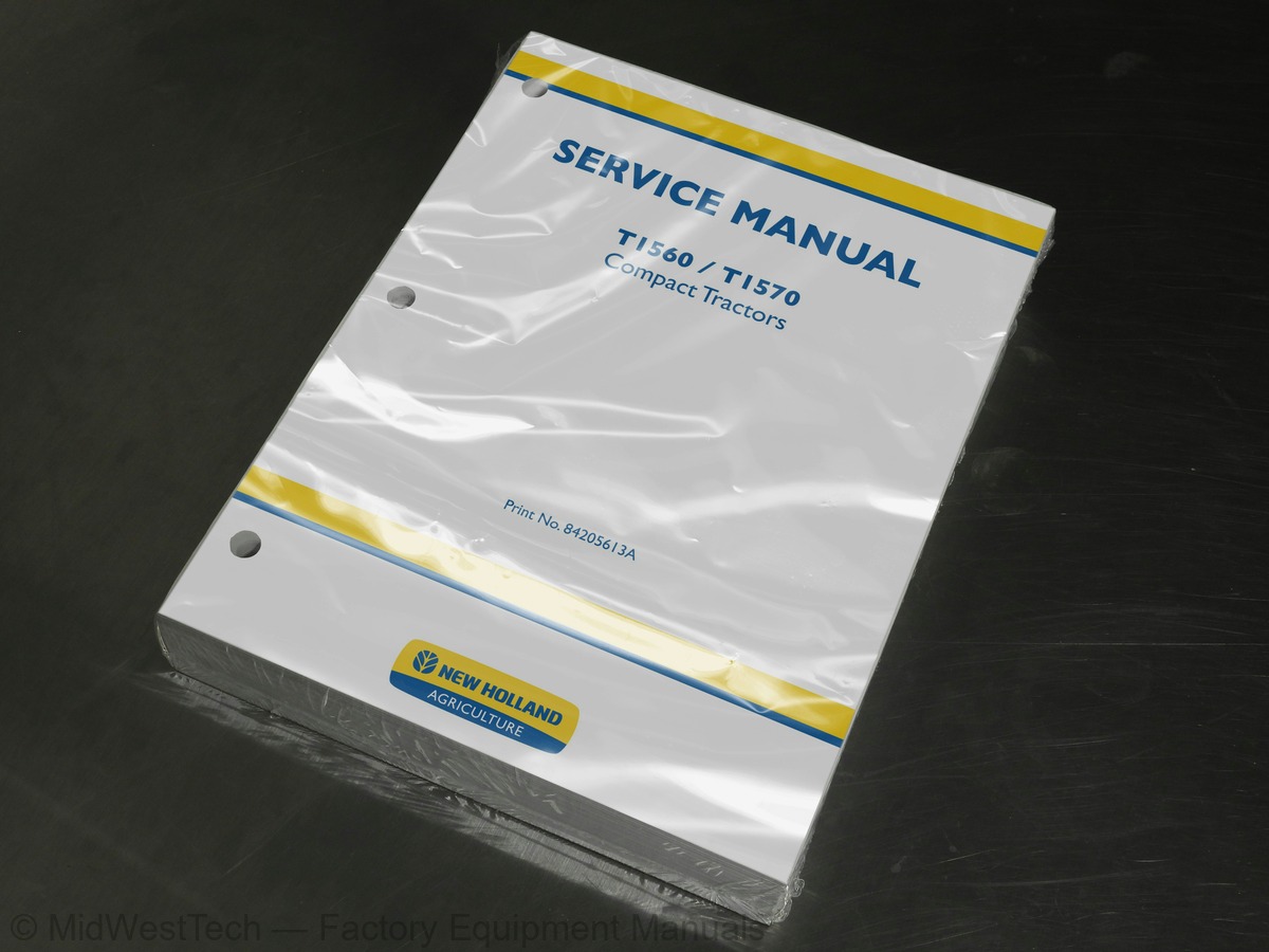
New Holland T1560, T1570 Compact Tractor Service Manual
491 pages · Publication 84205613A
Added to your cart. View cart
- Models
- T1560, T1570
- Manual type
- Service Manual
- Pages
- 491
- Publication
- 84205613A
- Condition
- Brand new
What's inside
From the manual's own table of contents: 16 sections, 259 entries. See sample pages (PDF, 652 KB)
SECTION 00 -- GENERAL -- CHAPTER 18 topics
- Introduction
- International Symbols
- Specifications
- General Dimensions
- Minimum Hardware Tightening Torques
- Metric Bolt Torque Specifications
- Lubricants
- Adjustments
SECTION 10 -- ENGINE -- CHAPTER 126 topics
- Cooling System
- Engine Bolt Torque Specifications
- Engine Fuel System Bolt Torque Specifications
- Special Tools
- Compression Test and Tools
- Description of Operation -- Engine
- Cylinder Head and Valve Train Components
- Cylinder Block Assembly
- Troubleshooting
- Overhaul -- Engine
- Engine
- Preparation
- Fuel Injector and Glow Plug
- Removal
- Oil Pressure Switch
- Temperature Sending Switch and Alternator
- Fan, Water Pump, and External Oil Tube
- Head Cover
- Rocker Arm Shaft and Support Bracket
- Cylinder Head
- Valve Tappet
- Fuel Shutoff Solenoid
- Timing Gear Cover
- Timing Gears and Camshaft
- Oil Sump
- Oil Suction Pipe and Strainer
SECTION 10 -- ENGINE -- CHAPTER 227 topics
- Fuel System Components
- Description of Operation -- Injection Pump
- General
- Governor System
- Injectors
- Breather Valve
- Fuel Variation Mechanism
- CTD (Compact Timing Device) Mechanism
- Delivery Valves
- Fuel Delivery
- Injection Pump
- Repair
- Installation
- Timing and Governor Adjustment
- Original Pump and Drive Components
- New Pump or Drive Component
- Spill-timing Procedure
- Bleeding the Fuel System
- Fuel Settings Adjustments
- Fuel Screw/High Idle
- Description of Operation -- Governor
- Governor
- Disassembly
- Assembly
- Description of Operation -- Injectors
- Assembly and Adjustment
- Description of Operation -- Engine Breather Valve
SECTION 18 -- CLUTCH -- CHAPTER 112 topics
- Bolt Torques
- Description of Operation - Single Clutch
- x 3 Gear Transmission
- HST Models
- HST Drive Transmission
- Clutch Pedal Assembly
- Overhaul - Single Clutch
- Single Clutch
- Inspection
- Adjustments - Single Clutch
- Free-play Adjustment - HST Models Only
- Clutch Stop - HST and 9 x 3 Transmission Models
SECTION 21 -- TRANSMISSION -- CHAPTER 113 topics
- General Bolt Torque Specifications
- Description of Operation
- Separating the Tractor
- Transmission Assembly
- Single Clutch Input Shaft
- Main Gear Shifter Rod
- Main Shaft
- Reverse Idler Shaft
- Single Clutch Countershaft
- Single Clutch PTO Countershaft
- FWD Shift Rod
- Rear Main Shaft
- Range Gear Shifter Rod
SECTION 25 -- FWD FRONT AXLE -- CHAPTER 123 topics
- Four Wheel Drive
- Bolt Torque Specifications
- Description of Operation -- Front-Wheel Drive Front Axle
- Overhaul
- Front-wheel Drive Front Axle
- Reduction Gear -- Drop Box
- Front Axle and Differential
- Drive Pinion
- Front Axle
- Inspection and Repair
- Differential
- Gear Reduction -- Drop Box
- Differential Gear
- Axle and Differential
- Ring Gear-to-pinion Backlash Check and Adjustment
- Ring Gear to Pinion Adjustment
- Reduction Gear Box
- Idler Case Vertical Shimming Procedure
- Bevel Gear-to-Pinion Backlash Check
- Front Axle -- 4WD
- Front Wheel Toe-in
- Checking Toe-In
- Adjusting Toe-In
SECTION 27 -- DIFFERENTIAL, REAR AXLE -- CHAPTER 19 topics
- Ring Gear and Pinion Gear Pattern Specification and Adjustment
- Differential Assembly
- Differential Lock
- Disassembly (with HST Transmission)
- Disassembly (with 9 x 3 Transmission)
- Assembly and Installation
- Rear Axle
- Axle Seal
- Rear Axle/Center Housing
SECTION 29 -- TRANSMISSION -- CHAPTER 118 topics
- Hydrostatic Transmission
- Description of Operation - Hydrostatic Transmission
- Variable Displacement Pump
- Operation
- Fixed Displacement Motor
- Fluid Flow
- Neutral Position
- Forward Position
- Reverse Position
- Hydrostatic Unit
- Precautions Before Disassembly
- Hydrostatic Pump
- Hydrostatic Motor
- Hydrostatic Motor Shaft
- Charge Pump
- Swash Plate
- HST Piston Pump Cylinder Block
- HST Motor Cylinder Block
SECTION 29 -- TRANSMISSION -- CHAPTER 213 topics
- Description of Operation - Hydrostatic Transmission Gearbox
- HST Unit
- Power Flow
- Gearbox
- Overhaul - Transmission Gearbox
- HST Transmission
- Transmission Case
- PTO Input Shaft
- Transmission Input Shaft
- FWD Drive Shaft
- Drive Pinion Shaft
- PTO Countershaft Removal
- PTO Countershaft
SECTION 31 -- POWER TAKE--OFF -- CHAPTER 19 topics
- Power Take-off Drive -- Hydrostatic Transmission
- Overhaul -- Power Take-off
- Power Take-off
- Output Shaft
- Centre Countershaft
- One-way Clutch
- Rear Countershaft
- Front Countershaft
- Shifter
SECTION 33 -- BRAKES -- CHAPTER 15 topics
- Rear Axle and Brakes
- Brake Operation
- Parking Brake
- Brakes and Final Pinion Overhaul
- Brake Linkage Adjustment
SECTION 35 -- HYDRAULIC SYSTEM -- CHAPTER 117 topics
- Description of Operation - Hydraulic System
- Hydraulic Fluid Filter
- Combination System Relief - Diverter Valve Manifold Assembly
- Control Valve Assembly (HPL)
- Neutral Position - Fluid Flow
- Raising Position - Fluid Flow
- Lowering Position - Fluid Flow
- Bypass Spool - Fluid Flow - Closed Position
- Bypass Spool - Fluid Flow - Open Position
- Unload Valve
- Flow Control Valve
- Linkage Operation - Single Lever - Position Control
- Position Control Operation - Neutral Position to Raise
- Raise Position to Neutral Position
- Neutral Position to Lowering Position
- Overhaul - Lift Cylinder
- Lift Cylinder
SECTION 41 -- STEERING -- CHAPTER 114 topics
- Power Steering System
- Drive Shaft
- Gerotor Pump
- Check Valve
- Relief Valve
- Power Steering Pump
- Power Steering Cylinder
- Power Steering Operation
- Fluid Flow - Neutral Position
- Fluid Flow - Left Turn
- Fluid Flow - Right Turn
- Power Steering Manual Operation
- Steering Control Motor
- Steering Cylinder
SECTION 55 -- ELECTRICAL SYSTEM -- CHAPTER 116 topics
- Component Location and Function
- Ground Locations
- Description and Testing -- Electrical System Components
- Battery
- Electrolyte Level
- Fusible Link
- Replacement
- Fuse Block
- Key Switch
- Testing
- Heat Position
- Light Switch
- Headlights
- Hazard/Turn Signal Combination Switch
- Transmission Range Safety Switch
- Description
SECTION 55 -- ELECTRICAL SYSTEM -- CHAPTER 36 topics
- Instrument Panel Identification
- Instrument Panel
- Coolant Temperature Gauge
- Fuel Gauge
- Instrument Panel assembly
- Instrument Panel installation
SECTION 55 -- ELECTRICAL SYSTEM -- CHAPTER 427 topics
- Specifications -- Alternator
- Description of Operation -- Charging System
- Charging Circuit
- Principle of IC Regulator
- Troubleshooting -- Alternator
- No Charging
- Insufficient Charging
- Overcharge
- Unstable Charging Circuit
- Abnormal Noise of Alternator
- Testing -- Alternator
- Preliminary Alternator Tests
- Alternator Drive Belt
- Alternator Output
- Alternator
- Alternator Bench Check
- Specifications -- Starter Motor
- Description of Operation -- Starting System
- Starter Motor Assembly
- Starter Solenoid
- Pinion Clutch
- Troubleshooting -- Starter Motor
- Pinion Shaft Fails to Advance
- Pinion Motor Rotates but No Rotation Transmitted to Engine
- Motor Rotates Before Pinion Meshes with Ring Gear
- Pinion Meshes with Ring Gear but Starting Motor Fails to Turn
- Motor Fails to Stop after Engine Starts and Key Switch is Turned Off
Inside this manual
Real pages from this service manual (491 pages). Open the sample pages (PDF, 651 KB)
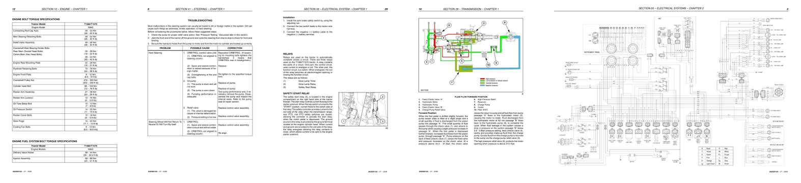
- Specifications, page 29: SECTION 10 -- ENGINE -- CHAPTER 1
- Troubleshooting, page 379: SECTION 41 -- STEERING -- CHAPTER 1
- Diagram, page 442: SECTION 55 -- ELECTRICAL SYSTEM -- CHAPTER 1
- Color page, page 233: SECTION 29 -- TRANSMISSION -- CHAPTER 1
- Foldout diagram, page 462: SECTION 55 -- ELECTRICAL SYSTEMS -- CHAPTER 2
This is a service manual
Here's how it compares to the other manual types.
Service manual
Factory repair procedures and technical information such as specifications, troubleshooting, and wiring and hydraulic diagrams, for the models and systems the manual covers. See What's inside for its topics.
Operator's manual
Safe operation, controls, maintenance schedules, lubrication points, inspections, and basic checks. Repair procedures are in the service manual.
Parts manual
Illustrated diagrams with factory part numbers for identifying components and ordering parts. Repair procedures are in the service manual.
Engine service manuals are sometimes sold separately, since certain machine models were offered with more than one engine option.
What it's used for
Factory manual for in-house farm and construction shop use. Straightforward, complete, and easy to follow. It contains the OEM information dealership service departments and parts counters use to diagnose problems, identify components, and perform maintenance or repairs correctly.
Service shops and owner/operators who repair their own equipment
Identifying correct parts and seeing how assemblies come apart and go back together
Keeping equipment running with less downtime
Factory manual, 491 pages
Quantity one is the manual described above.
Fast free USA shipping
Ships in 1 business day.
60-day returns
Free if the mistake is ours. A manual ordered in error must come back unopened in its shrink-wrap; you pay return shipping and a 20% restocking fee applies. Return policy
Binder not included
Manuals over about 300 pages may need a standard 3-ring binder, which you can buy locally to keep the pages organized for shop use.
Questions about model, serial number, engine coverage or contents? Contact us before purchasing and we'll help confirm it's the right manual. Please verify the manual type, machine model, serial number range and engine coverage before purchasing: manuals ordered in error carry a 20% restocking fee (return policy).