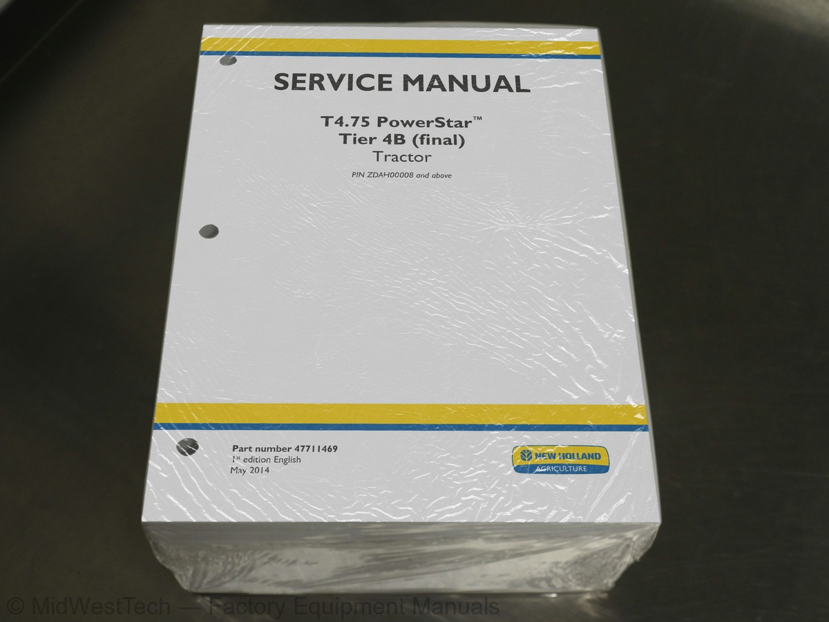
New Holland T4.75 PowerStar Tier 4B Tractor Service Manual
1,972 pages · Publication 47711469
Added to your cart. View cart
- Models
- T4.75 PowerStar Tier 4B
- Serial coverage
- PIN ZDAH00008 and above
- Manual type
- Service Manual
- Pages
- 1,972
- Publication
- 47711469
- Condition
- Brand new
What's inside
From the manual's own table of contents: 236 topics. See sample pages (PDF, 658 KB)
- Advice
- Safety rules SAFETY REGULATIONS
- Personal safety CAB AIR CONDITIONING SYSTEM
- Basic instructions
- Special tools NOTES FOR EQUIPMENT
- Consumables
- Part identification
- Sectional view (*)
- Dynamic description (*)
- Adjust (*)
- Adjust engagement control (*)
- Remove (*)
- Install (*)
- Adjust cable (*)
- Torque (*)
- General specification (*)
- Special tools (*)
- Disassemble clutch levers (*)
- Assemble clutch levers (*)
- Reseal (*)
- Overhaul 11”/11” dual clutch (*)
- Alignment – 11"/11" dual clutch release (*)
- Troubleshooting (*)
- Torque
Show all 236 topics
- General specification
- Special tools
- Adjust - Forward / Reverse control cable (*)
- Adjust - Gear and range cables (*)
- Remove – Rear transmission-gearbox case unit
- Install – Rear transmission-gearbox case unit
- Exploded view – 8 x 8 Shift forks and rails (*)
- Exploded view – 12 x 12 Shift forks and rails (*)
- Sectional view
- Static description
- Remove - Drive gears
- Disassemble - Input shaft
- Assemble - Input shaft (*)
- Disassemble - Output shaft (*)
- Assemble - Output shaft (*)
- Install - Drive gears
- Remove - Range gears (12 x 12)
- Install - Range gears (12 x 12)
- Adjust - Pinion bearing pre-load (*)
- Static description (*)
- Remove - Rear transmission-gearbox (*)
- Install - Rear transmission gearbox (*)
- General specification of the Mechanical Inching spool (*)
- General specification Mechanical Shuttle spool (*)
- General specification Mechanical PTO spool (*)
- General specification Mechanical Ground Speed PTO spool (as variante) (*)
- Hydraulic schema and definition of external couplers (*)
- Exploded view - Power Shuttle transmission control valve (*)
- Adjust - Forward/Reverse control lever (*)
- Adjust - Hydraulic Power Take-Off (PTO) (*)
- Remove - Drive gears (*)
- Disassemble - Input shaft (*)
- Install - Drive gears (*)
- Disassemble (*)
- Assemble (*)
- Adjust – Control cable
- Remove
- Install
- Disassemble
- Assemble
- Dynamic description
- Troubleshooting
- External view
- Sectional view without differential lock
- Sectional view with self-locking differential with limited slip
- Adjust
- Overhaul
- Replace
- General specification Bevel gear pair and differential
- Dynamic description - 540, 540/540E Power Take-Off (PTO) engagement (*)
- Dynamic description of the speed selector for the 540/540E rpm Power Take-Off (PTO) (*)
- General specification Cable operated PTO clutch spool (*)
- Dynamic description 540 rpm, 540/540E rpm Power Take-Off (PTO) engagement (*)
- Dynamic description 540/540E rpm PTO speed selection (*)
- General specification Mechanical PTO 540 rpm (*)
- General specification 540 rpm hydraulic PTO (*)
- Static description mechanical transmission (*)
- Static description power shuttle transmission (*)
- Exploded view 540 rpm mechanical PTO (*)
- Exploded view 540 rpm hydraulic PTO (*)
- Remove mechanical PTO brake disc (*)
- Install mechanical PTO brake disc (*)
- Remove Hydraulic PTO brake discs (*)
- Install Hydraulic PTO brake discs (*)
- Disassemble 540 rpm hydraulic PTO (*)
- Assemble 540 rpm hydraulic PTO (*)
- General specification 540/540E rpm hydraulic PTO (*)
- General specification - Mechanical PTO 540/540E rpm (*)
- Exploded view (*)
- Disassemble mechanical PTO 540/540E rpm (*)
- Assemble mechanical PTO 540/540E rpm (*)
- Overhaul (*)
- Disassemble 540/540E rpm hydraulic PTO (*)
- Assemble 540/540E rpm hydraulic PTO (*)
- Adjust speed selection control cable – 540/540E rpm
- Adjust 540/540E rpm (PTO) clutch spool adjustment (*)
- Exploded view
- Adjust mechanically controlled brakes
- Adjust of the hydraulically controlled brakes
- Bleed
- Adjust – Retaining system of the parking lock (*)
- Open center mechanical remote valve - Special tools
- Open center mechanical remote valve - Torque
- Open center mechanical remote valve - General specification
- Open center mechanical remote valve - Static description
- Open center mechanical remote valve - Dynamic description
- Open center mechanical remote valve - Exploded view
- Open center mechanical remote valve - Hydraulic schema
- Open center mechanical remote valve - Disassemble with the unit removed
- Open center mechanical remote valve - Leakage test
- Adjust of the control cables
- Service instruction QUICK COUPLER MAINTENANCE
- Adjust – Sensitivity
- Replace Pins
- Functional diagram
- Overview
- Static description – Operation
- Assemble (with control valve removed)
- Test
- Pressure test
- Remove Standard axle
- Install Standard Axle
- General specification - Ambient temperature versus manifold pressure gauge reading (*)
- General specification - Temperature/pressure Chart (*)
- General specification high pressure switch (*)
- Component identification (*)
- Check (*)
- Service instruction (*)
- Service instruction - Precautionary statements (*)
- Visual inspection (*)
- Preliminary test (*)
- Pressure test Example 1 (*)
- Pressure test Example 2 (*)
- Pressure test Example 3 (*)
- Pressure test Example 4 (*)
- Pressure test - Example 5 (*)
- Pressure test - Example 6 (*)
- Pressure test - Example 7 (*)
- Pressure test - Example 8 (*)
- Identification for platform models (*)
- Identification for cab models (*)
- Identification for platform models
- Identification for cab models
- Component localisation 01 - engine harness 1, LH side view
- Component localisation 02 - engine harness 1, RH side view
- Component localisation 03 - engine harness 2, LH side view
- Component localisation 04 - engine harness 2, RH side view
- Component localisation 05 - mechanical transmission harness
- Component localisation 06 - main platform harness, left-hand side view (*)
- Component localisation 06 - main cab harness, left-hand side view (*)
- Component localisation 07 - main platform harness, right-hand side view (*)
- Component localisation 07 - main cab harness, right-hand side view (*)
- Component localisation 08 - cab roof harness (*)
- Component localisation - cab roof harness
- Component localisation 09 - hood harness
- Electrical schema HOW TO USE THE WIRING DIAGRAMS
- Wiring standard COLOR CODE OF THE WIRING
- Identification in order of component (*)
- TRIBUTION UNIT – PDU) (*)
- Electrical schematic sheet 02 FUSES (*)
- Electrical schematic sheet 03 POWER TAKE OFF (PTO) AND SAFETY CIRCUITS (*)
- Electrical schematic sheet 05 AIR CONDITIONING (*)
- Electrical schematic sheet 06 WORKLAMPS (*)
- Electrical schematic sheet 07 LIGHTING (*)
- Check
- Component localisation
- Tension adjust belt
- Check - SYSTEM TESTING AND TROUBLESHOOTING
- Electrical test
- Charging
- Electrical schema Analog Digital Instrument Cluster (ADIC)
- View HH MENU ACCESS
- View HH MENU of Analog Digital Instrument Cluster (ADIC) [ZC]
- H3 - Configurations and options of Analog Digital Instrument Cluster (ADIC) [ZC]
- H4 - View software revision level of Analog Digital Instrument Cluster (ADIC) [ZC]
- H5 - Switch operation test of Analog Digital Instrument Cluster (ADIC) [ZC]
- H9 - Voltmeter diagnostic of Analog Digital Instrument Cluster (ADIC) [ZC]
- HB - Display stored fault codes of Analog Digital Instrument Cluster (ADIC) [ZC]
- HC - Clear all stored fault codes of Analog Digital Instrument Cluster (ADIC) [ZC]
- HF - View controller hardware information of Analog Digital Instrument Cluster (ADIC) [ZC]
- Dynamic description (ADIC) programmable display
- Dynamic description dashboard/display brightness adjustment
- Dynamic description Speed calibration
- Dynamic description programming maintenance work
- Dynamic description audible warning on/off
- Dynamic description of the DPF (Diesel Particulate Filter) regeneration
- Dynamic description oil change counter reset
- Dynamic description fault codes display
- Static description alarms
- Dynamic description setting hours worked
- 3293-Fuel Metering Unit: maximum positive deviation of rail pressure exceeded
- 3406-ECU Power stages: Over temperature error on the Turbocharger PWM output power stage
- 3699-EEPROM: Error in EEPROM block EEPData1, SD correction can not be calculated
- 3721-Lambda sensor: Fault check to indicate SPI chip error of lambda sensor
- CH-HOT OIL WARNING: displayed above 100 degrees C
- CL-COLD OIL WARNING: displayed below 20 degrees C
- U17-Seat switch not activated
- U18-Correct start up procedure not used
- U19-Oil temperature < 10 °C, calibration is not possible
- U31-Wheel speed sensed
- U36-Calibration value too high
- U37-Calibration value too low
- 14002-Rear PTO speed sensor short to GND [only MECH]
- 14015-5V reference voltage - too high
- 14016-5V reference voltage - too low
- 14021-Cranking line - shorted to +12V
- 14022-Cranking line - shorted to GND
- 14051-Fuel level sensor - short circuit to supply voltage or open circuit
- 14052-Fuel level sensor - short circuit to ground
- 14058-Seat switch closed over 25 hours
- 14091-Transmission Output Speed Sensor - Short To Vcc Or Open Circuit [only MECH]
- 14092-Trans out speed sensor shorted to GND [Only MECH]
- 14093-Seat switch signal short to + 12V or open circuit
- 14094-Seat switch - short circuit to ground
- 14901-Engine controller missing
- 3007-Coolant temperature sensor - signal above range maximum
- 3008-Coolant temperature signal - signal below range minimum
- 3024-Atmospheric pressure sensor - signal above range maximum
- 3025-Atmospheric pressure sensor - signal below range minimum
- 3051-Battery voltage to ECU - voltage too high
- 3052-Battery voltage to ECU - voltage too low
- Replace Control struts
- Replace Triangular articulation levers
- Remove Bucket support device (*)
- Install Bucket support device
- Disassemble Position indicator (*)
- Assemble Position indicator
- Replace Bushings
- Remove Right-hand upper guard (*)
- Install Right-hand upper guard (*)
- Remove left-hand side (*)
- Install left-hand (*)
Inside this manual
Real pages from this service manual (1,972 pages). Open the sample pages (PDF, 657 KB)

- Diagram, page 951: COMPO-
- Specifications, page 1,491: Electrical systems - FAULT CODES
- Troubleshooting, page 1,581: Electrical systems - FAULT CODES
- Color page, page 624: Hydraulic systems - Remote control valves
- Color page, page 741: Steering - Hydraulic control components
- Foldout diagram, page 1,049: Electrical systems - Harnesses and connectors
This is a service manual
Here's how it compares to the other manual types.
Service manual
Factory repair procedures and technical information such as specifications, troubleshooting, and wiring and hydraulic diagrams, for the models and systems the manual covers. See What's inside for its topics.
Operator's manual
Safe operation, controls, maintenance schedules, lubrication points, inspections, and basic checks. Repair procedures are in the service manual.
Parts manual
Illustrated diagrams with factory part numbers for identifying components and ordering parts. Repair procedures are in the service manual.
Engine service manuals are sometimes sold separately, since certain machine models were offered with more than one engine option.
What it's used for
Factory manual for in-house farm and construction shop use. Straightforward, complete, and easy to follow. It contains the OEM information dealership service departments and parts counters use to diagnose problems, identify components, and perform maintenance or repairs correctly.
Service shops and owner/operators who repair their own equipment
Identifying correct parts and seeing how assemblies come apart and go back together
Keeping equipment running with less downtime
Factory manual, 1,972 pages
Quantity one is the manual described above.
Fast free USA shipping
Ships in 1 business day.
60-day returns
Free if the mistake is ours. A manual ordered in error must come back unopened in its shrink-wrap; you pay return shipping and a 20% restocking fee applies. Return policy
Binder not included
Manuals over about 300 pages may need a standard 3-ring binder, which you can buy locally to keep the pages organized for shop use.
Questions about model, serial number, engine coverage or contents? Contact us before purchasing and we'll help confirm it's the right manual. Please verify the manual type, machine model, serial number range and engine coverage before purchasing: manuals ordered in error carry a 20% restocking fee (return policy).