New Holland TJ425, TJ450, TJ500 Tractor Service Manual
6,553 pages · Publication 87542227
Added to your cart. View cart
- Models
- TJ425, TJ450, TJ500
- Manual type
- Service Manual
- Pages
- 6,553
- Publication
- 87542227
- Condition
- Brand new
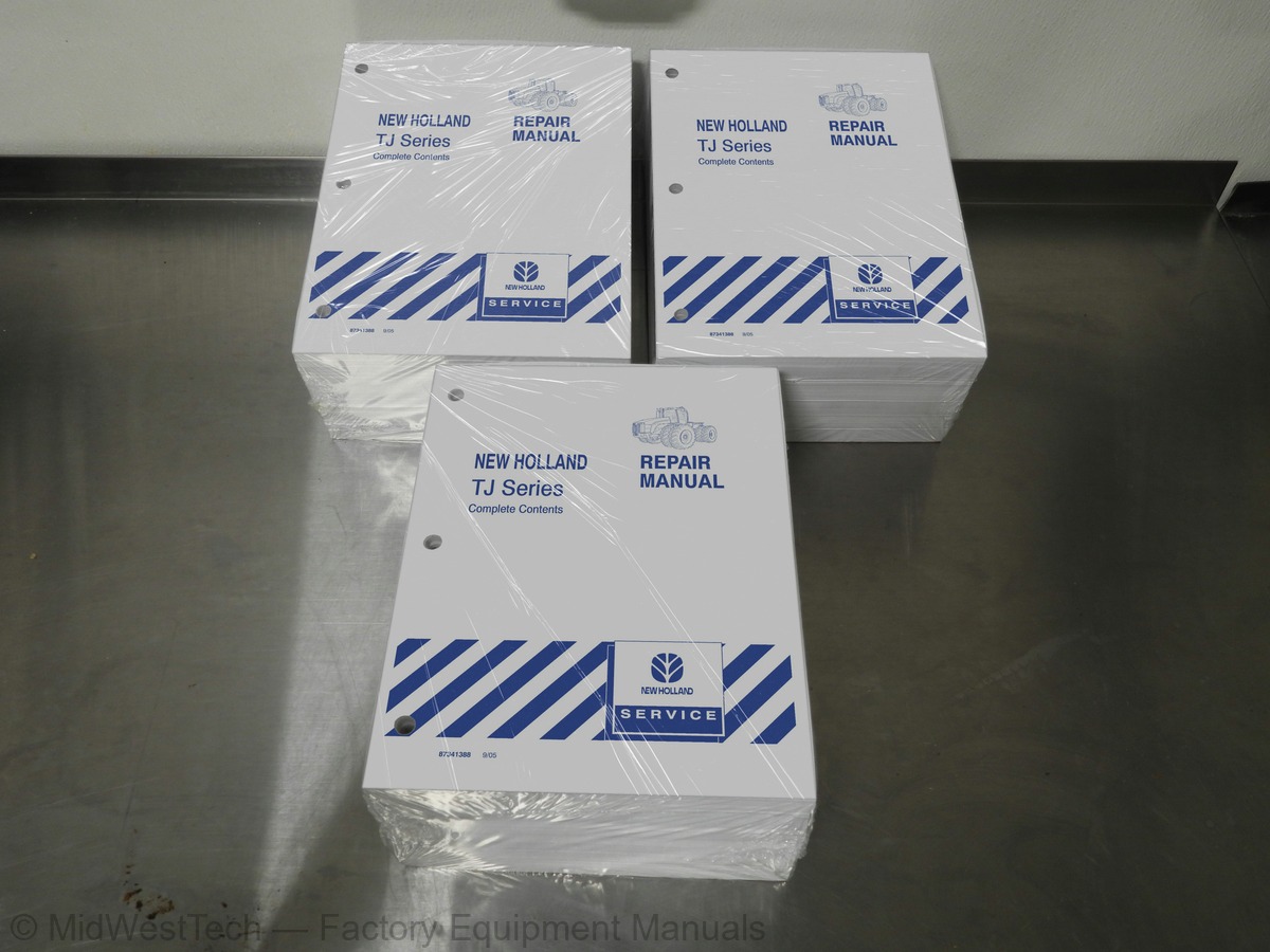
What's inside
From the manual's own table of contents: 286 sections, 474 entries. See sample pages (PDF, 1142 KB)
Show all 286 sections
Engine Air Induction System1 topic
- Primary and Secondary Filter Element Removal
Air Cleaner Housing Removal1 topic
- Aspirator Strata Tube Cleaning
General Safety Instrucitons1 topic
- Important Safety Notice
General Cleaning Instructions3 topics
- Solvent and Acid Cleaning
- Steam Cleaning
- Glass or Plastic Bead Cleaning
Engine Identification3 topics
- Engine Dataplate
- Fuel Injection Pump Dataplate
- ECM Dataplate
Specifications6 topics
- Air Intake System
- Cooling System
- Exhaust System
- Lubricating Oil System
- Electrical System
- Fuel System
Troubleshooting Symptoms Charts48 topics
- Communication Error Electronic Service Tool or Control Device
- Coolant Loss External
- Coolant Loss Internal
- Coolant Temperature Above Normal Gradual Overheat
- Coolant Temperature Is Above Normal - Sudden Overheat
- Coolant Temperature Is Below Normal
- Coolant in the Lubricating Oil
- Crankcase Gases (Blowby) Excessive
- Cranking Fuel Pressure Is Low
- Engine Acceleration or Response Poor
- Engine Decelerates Slowly
- Engine Difficult to Start or Will Not Start (Exhaust Smoke)
- Engine Difficult to Start or Will Not Start (No Exhaust Smoke)
- Engine Noise Excessive
- Engine Noise Excessive Combustion Knocks
- Engine Noise Excessive Connecting Rod
- Engine Noise Excessive Main Bearing
- Engine Noise Excessive Piston
- Engine Noise Excessive Turbocharger
- Engine Power Output Low
- Engine Runs Rough at Idle
- Engine Runs Rough or Misfires
- Engine Shuts Off Unexpectedly or Dies During Deceleration
- Engine Speed Surges at Low or High Idle
- Engine Speed Surges Under Load or in Operating Range
- Engine Speed Surges in PTO
- Engine Starts But Will Not Keep Running
- Engine Vibration Excessive
- Engine Will Not Crank or Cranks Slowly (Electric Starter)
- Engine Will Not Reach Rated Speed (RPM)
- Engine Will Not Shut Off
- Fault Code Warning Lamps Do Not Illuminate
- Fuel Consumption Excessive
- Fuel in Coolant
- Fuel in the Lubricating Oil
- Intake Manifold Air Temperature Above Specification
- Low Idle Adjust Switch Does Not Work
- Intake Manifold Pressure (Boost) is Below Normal
- Lubricating Oil Consumption Excessive
- Lubricating Oil Contaminated
- Lubricating Oil Pressure High
- Lubricating Oil Pressure Low
- Lubricating Oil Sludge in the Crankcase Excessive
- Lubricating Oil Temperature Above Specification
- Lubricating or Transmission Oil in the Coolant
- Smoke, White Excessive
- Smoke, Black Excessive
- Turbocharger Leaks Engine Oil or Fuel
Engine Noise Diagnostic Procedures General Information3 topics
- Main Bearing Noise
- Connecting Rod Bearing Noise
- Piston Noise
Service Tools1 topic
- Cylinder Block
Crankshaft Gear, Front (Crankshaft Installed) (001-018)1 topic
- General Information
Vibration Damper, Rubber (001-051)1 topic
- Cylinder Head
Rotor, CAPS Fuel Injection Pump (005-072)1 topic
- Inspect for Reuse
Flow Diagram, Lubricating Oil System2 topics
- Lubrication for the Turbocharger
- Lubrication for the Power Components
Cylinder Block - Specifications5 topics
- Bearings, Connecting Rod (001-005)
- Camshaft Bushings (001-010)
- Camshaft Gear (Camshaft Removed) (001-013)
- Conncecting Rod (001-014)
- Piston and Connecting Rod Assembly (001-054)
Cylinder Block - Torque Values5 topics
- Gear Housing, Front (001-033)
- Vibration Damper, Rubber (001-051)
- Crankshaft Wear Sleeve, Rear (001-067)
- Piston and Conecting Rod Assembly (001-054)
- Vibration Damper (001-052)
Cylinder Head - Specifications1 topic
- Valve, Cylinder Head (002-020)
Rocker Levers - Torque Values1 topic
- Rocker Lever Cover (003-011)
Fuel System - Torque Values2 topics
- Rotor, CAPS Fuel Injection Pump (005-072)
- Snubber, Rate Shape (005-081)
Injectors and Fuel Lines - Torque Values3 topics
- Fuel Drain Line Restriction (006-012)
- Fuel Filter Head Bracket (006-018)
- Injector Supply Lines (High Pressure) (006-051)
Lubricating Oil System - Specifications1 topic
- Lubricating Oil Pump (007-031)
Lubricating Oil System - Torque Values6 topics
- Engine Oil Heater (007-001)
- Lubricating Oil Cooler (007-003)
- Lubricating Oil Pan (007-025)
- Lubricating Oil Pressure Regulator (Main Rifle) (007-029)
- Lubricating Oil Suction Tube (Block-Mounted) (007-035)
- Lubricating Oil Thermostat (007-039)
Cooling System - Specifications1 topic
- Coolant Thermostat (008-013)
Cooling System - Torque Values2 topics
- Coolant Filter Head (008-007)
- Fan Spacer and Pulley (008-039)
Air Intake System - Specifications3 topics
- Air Intake Restriction (010-003)
- Axial Clearance (010-038)
- Radial Bearing Clearance (010-047)
Air Intake System - Torque Values5 topics
- Air Leaks, Air Intake and Exhaust Systems (010-024)
- Turbocharger Axial Clearance (010-038)
- Turbocharger Blade Damage (010-039)
- Turbocharger Radial Bearing Clearance (010-047)
- Turbocharger Turbine Seal Leaks (010-049)
Exhaust System - Specifications2 topics
- Exhaust Manifold, Dry (011-007)
- Exhaust Restriction (011-009)
Exhaust System - Torque Values1 topic
- Exhaust Manifold Dry (011-007)
Capscrew Markings and Torque Values2 topics
- Capscrew Markings and Torque Values - Metric
- Capscrew Markings and Torque Values - U.S. Customary
ECM Dataplate4 topics
- Front View
- Rear View
- Fuel Pump Side View
- Exhaust Side View
Diagnostic Fault Codes3 topics
- Fault Code Snapshot Data
- Engine Time Offset
- Duty Cycle Monitor
Fault Code 1111 topic
- ECM Microprocessor
Fault Code 1151 topic
- Engine Speed Sensor (ESS) Circuit
Fault Code 1212 topics
- Engine Position Sensor (EPS) Circuit
- Intake Manifold Pressure Sensor Circuit
Fault Code 1242 topics
- Accelerator Position Sensor Circuit
- Oil Pressure Sensor Circuit
Fault Code 1431 topic
- Coolant Temperature Sensor Circuit
Fault Code 1511 topic
- Intake Manifold Air Temperature Sensor Circuit
Fault Code 1551 topic
- Ambient Air Pressure Sensor Circuit
Fault Code 2341 topic
- Engine Overspeed Circuit
Fault Code 2352 topics
- Engine Coolant Level - Engine Protection
- Fuel Temperature Sensor Circuit
Fault Code 2683 topics
- Fuel Pressure Sensor Circuit
- Front Pumping Valve Circuit
- Rear Pumping Valve Circuit
Fault Code 2752 topics
- Front Pumping Element of the CAPS Fuel Pump
- Injection Control Valve Circuit
Fault Code 2771 topic
- Injection Control Valve
Fault Code 2783 topics
- Lift Pump Circuit
- Pumping Element
- Engine Speed Sensor
Fault Code 3281 topic
- Rear Pumping Element
Fault Code 3294 topics
- CAPS Injection Pump
- Sensor Supply Circuit
- Intake Air Heater Relay Circuit
- Remote Accelerator Control Circuit
Fault Code 4181 topic
- WIF Sensor Circuit
Fault Code 4221 topic
- Coolant Level Sensor Circuit
Fault Code 4291 topic
- Idle Validation Switch Circuit
Fault Code 4321 topic
- Accelerator Pedal Circuit
Fault Code 4341 topic
- Unswitched Battery Supply Circuit
Fault Code 4885 topics
- Communication Error - Electronic Service Tool or Control Device
- Fault Code Warning Lamps Stay On (No Apparent Reason)
- PTO Does Not Operate
- Smoke, Black -- Excessive
- Smoke, White -- Excessive
Engine Position Sensor (EPS) Circuit (019-039)1 topic
- Check for Short Circuit from Pin to Pin (019-039-040)
Engine Wiring Harness (019-043)1 topic
- Check for Short Circuit to Ground (019-046-039)
Idle Adjust Switch (019-052)1 topic
- Check for Short Circuit to Ground (019-052-039)
Idle Adjust Switch Circuit (019-053)2 topics
- Check for Short Circuit to Ground (019-053-039)
- Check for Short Circuit from Pin to Pin (019-053-040)
Idle Validation Switch (IVS) Circuit (019-055)3 topics
- Check for Short Circuit to Ground (019-055-039)
- Check for Short Circuit from Pin to Pin (019-055-040)
- Check for Short Circuit to External Voltage Source (019-055-043)
Intake Manifold Air Temperature Sensor Circuit (019-060)2 topics
- Check for Short Circuit to Ground (019-060-039)
- Check for Short Circuit from Pin to Pin (019-060-040)
Programmable Features and Parameters Not Correct (019-078)1 topic
- Adjust
Tachometer Circuit (019-083)2 topics
- Check for Short Circuit to Ground (019-083-039)
- Check for Short Circuit from Pin to Pin (019-083-040)
Throttle Position Sensor (TPS) (019-085)1 topic
- Check for Short Circuit to Ground (019-085-039)
Throttle Position Sensor (TPS) Circuit (019-086)3 topics
- Check for Short Circuit to Ground (019-086-039)
- Check for Short Circuit from Pin to Pin (019-086-040)
- Check for Short Circuit to External Voltage Source (019-086-043)
Unswitched Battery Supply Circuit (019-087)3 topics
- Resistance Check
- Check for Short Circuit to Ground (019-087-039)
- Check for Short Circuit from Pin to Pin (019-087-040)
Vehicle Speed Sensor, Digital Input (019-090)2 topics
- Check for Short Circuit to Ground (019-090-039)
- Check for Short Circuit from Pin to Pin (019-090-040)
Vehicle Speed Sensor, Magnetic Pick Up (019-091)1 topic
- Check for Short Circuit to Ground (019-091-039)
Engine Speed Sensor Circuit (019-106)1 topic
- Check for Short Circuit from Pin to Pin (019-106-040)
Fuel Pressure/Temperature Circuit (019-154)1 topic
- Check for Short Circuit to Ground (019-154-039)
Cold Start Aid Circuit (019-164)3 topics
- Check for Short Circuit to Ground (019-164-039)
- Check for Short Circuit from Pin to Pin (019-164-040)
- Check for Short Circuit to External Voltage Source (019-164-043)
Capscrew Markings and Torque Values - U.S. Customary2 topics
- Coolant Temperature is Above Normal -- Sudden Overheat
- Engine Will Not Crank or Cranks Slowly (Air Starter)
Crankshaft Wear Sleeve, Rear (001-067)3 topics
- Tool No
- Tool Description
- Tool Illustration
Inside this manual
Real pages from this service manual (6,553 pages). Open the sample pages (PDF, 1141 KB)

- Specifications, page 871: Lubricating Oil System - Specifications
- Troubleshooting, page 2,083: Fault Code 133
- Diagram, page 2,487: Fault Code 489
- Color page, page 3,029: September 2001
- Color page, page 6,331: Left Click Mouse On:Active Terminator - Cab
- Foldout diagram (color): CIRCUIT DESCRIPTION
This is a service manual
Here's how it compares to the other manual types.
Service manual
Factory repair procedures and technical information such as specifications, troubleshooting, and wiring and hydraulic diagrams, for the models and systems the manual covers. See What's inside for its topics.
Operator's manual
Safe operation, controls, maintenance schedules, lubrication points, inspections, and basic checks. Repair procedures are in the service manual.
Parts manual
Illustrated diagrams with factory part numbers for identifying components and ordering parts. Repair procedures are in the service manual.
Engine service manuals are sometimes sold separately, since certain machine models were offered with more than one engine option.
What it's used for
Factory manual for in-house farm and construction shop use. Straightforward, complete, and easy to follow. It contains the OEM information dealership service departments and parts counters use to diagnose problems, identify components, and perform maintenance or repairs correctly.
Service shops and owner/operators who repair their own equipment
Identifying correct parts and seeing how assemblies come apart and go back together
Keeping equipment running with less downtime
Factory manual, 6,553 pages
Quantity one is the manual described above.
Fast free USA shipping
Ships in 1 business day.
60-day returns
Free if the mistake is ours. A manual ordered in error must come back unopened in its shrink-wrap; you pay return shipping and a 20% restocking fee applies. Return policy
Binder not included
Manuals over about 300 pages may need a standard 3-ring binder, which you can buy locally to keep the pages organized for shop use.
Questions about model, serial number, engine coverage or contents? Contact us before purchasing and we'll help confirm it's the right manual. Please verify the manual type, machine model, serial number range and engine coverage before purchasing: manuals ordered in error carry a 20% restocking fee (return policy).