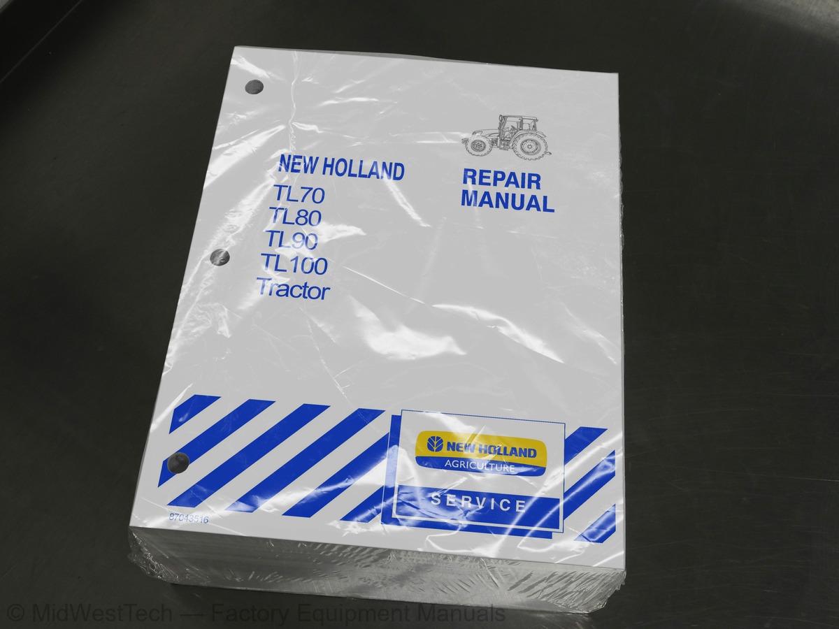
New Holland TL70, TL80, TL90, TL100 Tractor Service Manual
1,687 pages · Publication 87043516
Added to your cart. View cart
What's inside
From the manual's own table of contents: 105 sections, 362 entries. See sample pages (PDF, 801 KB)
General24 topics
- SECTION 00 - GENERAL GUIDELINES
- SECTION 10 - ENGINE
- SECTION 18 - CLUTCH
- SECTION 21 - TRANSMISSIONS
- SECTION 23 - DRIVE LINES
- SECTION 25 - FRONT AXLE MECHANICAL TRANSMISSION
- SECTION 27 - REAR AXLE MECHANICAL TRANSMISSION
- SECTION 31 - POWER TAKE-OFF
- SECTION 33 - BRAKES
- SECTION 35 - HYDRAULIC SYSTEMS
- SECTION 41 - STEERING
- SECTION 44 - AXLES AND WHEELS
- SECTION 50 - AUXILIARY UNITS
- SECTION 55 - ELECTRICAL SYSTEM
- SECTION 90 - BODYWORK AND DRIVING POSITION
- General Instructions
- General specifications
- Data
- Tightening Torques
- Tools
- Cross--sectional views
- Lubrication diagram
- Cooling system diagram
- Fault diagnosis
10 414 10 Coolant pump and generator drive belts. Tension adjustment6 topics
- Clutches. General specifications
- Tightening Torques
- Tools
- Cross--sectional views
- Fault diagnosis
- Checks, dimensions and repairs
18 110 30 Dual Clutch 12”/12” -- Test bench overhaul and adjustment8 topics
- Transmission and range gear. Data
- Tools
- Cross--sectional views
- Description and Operation
- Fault diagnosis
- Transmission with range gear and reverser. Data
- Description and Operation
- Fault diagnosis
21 110 85 Clutch--reverser casing. Disassembly--Assembly4 topics
- OVER DRIVE transmission data
- Tightening Torques
- Cross--sectional views
- Description and Operation
21 110 87 OVER DRIVE Casing -- Replacement5 topics
- Data
- Tightening Torques
- Tools
- Description and Operation
- Fault diagnosis
21 110 87 Reverser--clutch casing and creeper unit D.A3 topics
- Tools
- Cross--sectional views
- Description and Operation
21 110 88 Clutch casing with Power Shuttle and Dual Command (HI--LO) units D.A3 topics
- Clutch (B) D.A
- Fault code decoding
- Description of operation and hydraulic diagrams
Show all 106 sections
23 202 52 Drive gear housing R.I3 topics
- Cross--sectional views
- Description of LIM--SLIP self--locking differential operation
- Description of front differential lock operation
25 108 46 Steering knuckle pins and bearings3 topics
- Adjustments
- Cross--sectional views
- Description and Operation
27 120 32 Epicyclic final drive D.A4 topics
- Tightening Torques
- Cross--sectional views
- Description of operation
- Fault diagnosis
31 112 48 Driven shaft and other parts D.A2 topics
- Description, operation and hydraulic diagrams
- Fault diagnosis
31 116 55 Power take--off driving shaft D.A3 topics
- Data
- Description and Operation
- Fault diagnosis
33 202 60 Service brake cylinder. R.I25 topics
- Precautionary Statements
- Hydraulic System -- General Description
- Hydraulic System Configurations (Table 1)
- Low Pressure, Steering and Lubrication System
- High Pressure System Description and Operation
- Oil Flow Priority (Table 2)
- Hydraulic Power Lift (HPL) Control
- Lift-O-Matic
- Auxiliary Control Valves -- General Description
- Adding Rear Remote Valves
- Single and Double Acting Cylinders
- Remote Valves with Automatic Release
- Remote Valves with Float Setting
- Rear Remote Valve Control Levers
- Regulating Oil Flow
- Optional Joystick Control for Mid-Mount Remote Valves
- Mid-Mount Remote Control Valves (Optional)
- Auxiliary Control Valve Oil Flow
- Double-Acting Valve with Automatic Detent Release and Float Position -- Float Phase
- Double-Acting Valve with Automatic Detent Release and Float Position -- Lift Phase
- Double-Acting Valve with Automatic Detent Release and Float Position -- Lower Phase
- Double-Acting Valve without Automatic Detent Release -- Lift Phase
- Double-Acting Valve without Automatic Detent Release -- Lower Phase
- Single-Acting Valve without Automatic Detent Release -- Lift Phase
- Single-Acting Valve without Automatic Detent Release -- Lower Phase
35 104 30 Lift Oil Pump -- Disassembly--Assembly2 topics
- Testing
- Adjustment of the Automatic Detent Release Pressure
35 116 33 Supplementary Cylinder D.A7 topics
- Data
- Special Tools
- Specifications
- Torque Valves
- HPL Control Valve
- Hydraulic Power Lift Troubleshooting
- Hydraulic Power Lift (HPL) Control Valve Oil Flow
35 110 08 Linkage Adjustments1 topic
- Operations to be Performed to Adjust Upper Stroke Limit of the Lift-O-Matic Device
35 110 17 Rear Lift External Controls D.A1 topic
- Lift Adjustments
35 114 14 Lift Control Valve D.A4 topics
- Auxiliary Control Valve Cross-sectional Views
- TL Standard Kontak Remote Control Valves
- Standard Kontak Tube Arrangement
- Kontak Mid Mount Remotes
35 204 46 Auxiliary Control Valves D.A8 topics
- TL Deluxe Hydraulic Systems Containing Rexroth Remote Control Valves
- Rexroth Auxiliary Control Valves
- Unload Valve
- Deluxe Rear Remote Valve Arrangement (BOSCH)
- Deluxe Rear Remote Valve Arrangement (BOSCH with Factory Installed Option)
- Bosch Type Rear Remote Valve
- TL Deluxe Hydraulic Systems Containing BOSCH Type Remote Valves
- Bosch Closed-center Remote Control Valves With Open-center Pump
35 204 46 BOSCH Control Valves Disassembly and Assembly2 topics
- Connecting Plate
- Low-Pressure, Steering and Lubrication Circuit -- Description and Operation
35 104 Low-Pressure Circuit Hydraulic Pump20 topics
- Power Shuttle -- Hydraulic System
- Hydraulic Power Shuttle Transmission
- Oil Flow
- Low Pressure, Steering and Lubrication Circuit Oil Flow
- Power Take-Off [Electro-Hydraulic]
- Dual Command (HI-LO)
- Dual Command 12 Speed Power Shift
- Power Shuttle and Dual Command (HI-LO)
- Hydrostatic Steering Hydraulic Pump
- Electro-hydraulic PTO Data
- Data on Control Valve with Solenoid Valves
- Steering System
- Special Tools
- Cross Sectional Views
- Dual Command (HI-LO) Troubleshooting (Front Clutch)
- Dual Command (HI-LO) Troubleshooting (Rear Clutch)
- Hydraulically Controlled Differential Lock Troubleshooting
- Front Axle Hydraulic Differential Lock Troubleshooting
- Hydrostatic Steering Troubleshooting
- Electro-Hydraulic Drive Gear Troubleshooting
21 168 23 Dual Command (HI-LO) Control Valve D.A8 topics
- Cross--sectional views
- Description and Operation
- Trailer brake control valve hydraulic circuit diagram with KONTAK control valves
- Trailer brakes control valve hydraulic circuit diagram with BOSCH control valves
- Functional testing and troubleshooting
- Details of electronic lift components
- Fault code decoding
- Diagnostics
35 138 20 Hydraulic control valve R. I3 topics
- Components and operating diagrams
- Fault diagnosis
- Tools
41 216 20 Front axle steering cylinder R.I1 topic
- Fault diagnosis and equipment
44 511 80 Checking 4 WD front wheel alignment11 topics
- Safety regulations
- General specifications
- Operating principles
- Main components of the cab air conditioning system
- Warnings for air conditioning system repair operations
- Cab controls
- Instructions for use -- air conditioning system
- Refrigerant recovery -- recycling and evacuation -- charging stations
- Electronic leak detector 380000314
- Air conditioning system maintenance
- Air conditioning system troubleshooting
55 000 Instruments5 topics
- Components
- Starting System
- Charging System
- Battery
- Electrical Circuits
Analog instruments4 topics
- Transmitters, sensors and switches
- Maintenance
- Electronic instruments
- Diagnostics
55 40440 Introduction6 topics
- Dashboard controls
- Operating controls, right--hand side
- Electronic lift control panel
- Controls on right--hand cab upright
- External controls
- Maintenance
55 000 Technical data10 topics
- Tightening torques
- Description and operation
- Troubleshooting
- System testing
- Removal--Installation
- Bench tests
- System testing and troubleshooting
- Removal--Installation
- Battery checking and maintenance
- Tests
55 100 Electrical Circuit Components71 topics
- Fuses and Relays (Version with cab)
- Fuses and Relays (Version without cab -- NASO)
- Fuses and Relays (Version without cab -- ISO)
- Maxi Fuse Box
- Power Sockets
- Operator Presence Circuit
- Ground Location Points
- Symbols Used In Electrical Circuits
- Electrical Circuits (ISO, NASO)
- Linear Wiring Diagram Descriptions
- Starting and Recharging Circuit -- DIAGRAM A (ISO, NASO)
- Operator Presence Circuit -- DIAGRAM A/1 (ISO, NASO)
- (Version with cab) -- DIAGRAM B (ISO, NASO)
- Component locations for Wiring DIAGRAMS C -- D
- (Version without cab -- ISO) -- DIAGRAM C
- (Version without cab -- NASO) -- DIAGRAM D
- Direction Indicator and Hazard Lights Circuit (version with cab -- NASO) -- DIAGRAM E
- Component Locations for Wiring DIAGRAMS F -- G
- Direction Indicator and Hazard Lights Circuit (version without cab -- NASO) -- DIAGRAM F
- Direction Indicator and Hazard Lights Circuit (version without cab -- ISO) -- DIAGRAM G
- Component Locations for Wiring DIAGRAMS H -- I -- L
- DIAGRAM H
- (version with cab -- ISO ad NASO) DIAGRAM I
- (version with cab -- ISO and NASO) DIAGRAM L
- Component Locations for Wiring DIAGRAMS M -- N -- O
- DIAGRAM M
- DIAGRAM N
- Transmission Circuit (Version with Power Shuttle)(ISO and NASO) -- DIAGRAM O
- Component Locations for Wiring DIAGRAMS P -- Q -- R/1 -- R/2
- (HI--LO)] (ISO and NASO) -- DIAGRAM P
- (HI--LO)] (ISO and NASO) -- DIAGRAM Q
- DIAGRAM R/1
- DIAGRAM R/2
- Component Location for Wiring DIAGRAMS S -- T
- Differential Lock and Brake Light Circuits (version without cab -- ISO) -- DIAGRAM S
- Differential Lock and Brake Light Circuit (version without cab -- NASO) -- DIAGRAM T
- Component Locations for Wiring DIAGRAMS U/1 -- U/2
- Power Shuttle Circuit (ISO and NASO) -- DIAGRAM U/1
- Power Shuttle Circuit (ISO and NASO) -- DIAGRAM U/2
- Component Locations for Wiring DIAGRAM V
- Electronic Lift circuit (Model Bosch) (ISO) -- DIAGRAM V
- Component Location for Wiring DIAGRAMS Z -- X
- Dual Command (HI--LO) Circuit (ISO and NASO) -- DIAGRAM Z
- DIAGRAM X
- Component Locations for Wiring DIAGRAMS Y -- K
- Horn, Sensors and Transmitters Circuits (ISO and NASO) -- DIAGRAM Y
- Digital Instrument, Digital Clock Circuits (ISO) -- DIAGRAM K
- DIAGRAM W
- Low transmission oil pressure switch (83)
- Brake fluid level switch (18)
- Air filter clogged switch (12)
- Differential lock indicator switch (66)
- Lift status switch (127)
- Italia version trailer brake valve pressure switches (54)
- Brake light switch (16)
- Engine coolant temperature sensor (2)
- Fuel sediment filter switch (4)
- Handbrake switch (25)
- Dual Command (HI--LO) switch (19)
- Gear/Range lever position sensors (139--140--141)
- Parking switch (147)
- Engine oil pressure sensor (82)
- Switch (126) and clutch pedal potentiometer (129)
- Clutch pressure switches A and B (132--133) and oil temperature sensor (138)
- Alternator (87)
- FWD pressure switch (70)
- Fuel level indicator (67)
- Power Shuttle lever (130)
- Electronic lift arm position potentiometer (145)
- Seat safety switch (97)
- PTO speed sensor (62)
Inside this manual
Real pages from this service manual (1,687 pages). Open the sample pages (PDF, 800 KB)

- Specifications, page 720: SECTION 27 -- REAR AXLE MECHANICAL TRANSMISSION -- CHAPTER 1
- Troubleshooting, page 1,058: SECTION 35 -- HYDRAULIC SYSTEMS -- CHAPTER 9
- Diagram, page 1,604: SECTION 55 -- ELECTRICAL SYSTEM -- CHAPTER 7
- Color page: SECTION 35 -- HYDRAULIC SYSTEMS -- CHAPTER 5
- Color page: SECTION 10 -- ENGINE -- CHAPTER 1
- Foldout diagram (color): SECTION 31 -- POWER TAKE--OFF -- CHAPTER 2
Other manuals for this machine
Save 10% on 2 manuals, 15% on 3 or more. Other manuals for the TL70, TL80, TL90, TL100 are listed below. Editions cover different serial number ranges: check the serial coverage and tick only the ones that match your machine.
Added to your cart. View cart
This is a service manual
Here's how it compares to the other manual types.
Service manual
Factory repair procedures and technical information such as specifications, troubleshooting, and wiring and hydraulic diagrams, for the models and systems the manual covers. See What's inside for its topics.
Operator's manual
Safe operation, controls, maintenance schedules, lubrication points, inspections, and basic checks. Repair procedures are in the service manual.
Parts manual
Illustrated diagrams with factory part numbers for identifying components and ordering parts. Repair procedures are in the service manual.
Engine service manuals are sometimes sold separately, since certain machine models were offered with more than one engine option.
What it's used for
Factory manual for in-house farm and construction shop use. Straightforward, complete, and easy to follow. It contains the OEM information dealership service departments and parts counters use to diagnose problems, identify components, and perform maintenance or repairs correctly.
Service shops and owner/operators who repair their own equipment
Identifying correct parts and seeing how assemblies come apart and go back together
Keeping equipment running with less downtime
Factory manual, 1,687 pages
Quantity one is the manual described above.
Fast free USA shipping
Ships in 1 business day.
60-day returns
Free if the mistake is ours. A manual ordered in error must come back unopened in its shrink-wrap; you pay return shipping and a 20% restocking fee applies. Return policy
Binder not included
Manuals over about 300 pages may need a standard 3-ring binder, which you can buy locally to keep the pages organized for shop use.
Questions about model, serial number, engine coverage or contents? Contact us before purchasing and we'll help confirm it's the right manual. Please verify the manual type, machine model, serial number range and engine coverage before purchasing: manuals ordered in error carry a 20% restocking fee (return policy).