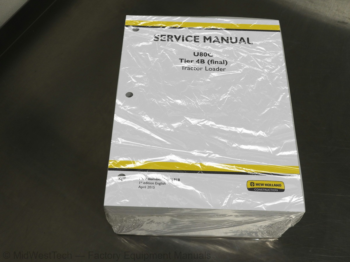
New Holland U80C Tier 4B Tractor Loader Service Manual
1,979 pages · Publication 47821918
Added to your cart. View cart
- Models
- U80C Tier 4B
- Manual type
- Service Manual
- Pages
- 1,979
- Publication
- 47821918
- Condition
- Brand new
What's inside
From the manual's own table of contents: 314 topics. See sample pages (PDF, 587 KB)
- Safety rules
- Safety rules Ductile iron
- Safety rules - Ecology and the environment
- Basic instructions Important notice regarding equipment servicing
- Basic instructions Battery
- Basic instructions Fuse and relay locations
- Basic instructions of fuse, relay and diode icons
- Basic instructions Diagnostic service tool port
- Basic instructions Welding on the machine
- Engine cooling system - Basic instructions
- Basic instructions Coolant shutoff valve
- Basic instructions Loader lift arm
- Basic instructions Hood
- Torque Minimum tightening torques for normal assembly
- Torque Standard torque data for hydraulics
- Abbreviation Measurements
- Capacities
- Consumables
- Engine lubrication system - General specification
- General specification - Diesel fuel
- General specification - Biodiesel fuels
- Product identification – machine orientation
- Product identification
- Product identification – machine overview
Show all 314 topics
- Engine and crankcase
- Fuel tanks
- Engine cooling system
- Fan and drive
- General specification
- Exploded view
- Drain fluid
- Filling
- Remove
- Install
- Replace oil and filter
- Dynamic description – Particulate Matter (PM) Catalyst
- Cleaning – Auto-regeneration
- Cleaning – Manual regeneration
- Disassemble
- Assemble
- Shroud - Remove
- Shroud - Install
- Torque
- Special tools
- Overview
- Exploded view Four wheel drive transmission (*)
- Exploded view Two wheel drive transmission (*)
- Hydraulic schema Two Wheel Drive Schematic (*)
- Hydraulic schema Four Wheel Drive Schematic (*)
- Check – Checking Supply Pump Pressure (4WD Only) (*)
- Test Checking Converter In Pressure
- Test Checking Regulated Clutch Pressure
- Test Checking Supply Pump Flow and Relief Pressure
- Test Checking Converter Out Pressure
- Test Checking Lubrication Pressure
- Test Checking Differential Lock Valve
- Pressure test 2 Wheel Drive, Test One - Engine at Idle 900 to 1100 rpm (*)
- Pressure test 2 Wheel Drive, Test Two - Engine at 2200 rpm (*)
- Tool connection Two Wheel Drive Port Identification (*)
- Tool connection Pressure Test Ports, Two Wheel Drive (*)
- Tool connection Pressure Test Ports 4 Wheel Drive (*)
- Tool connection Four Wheel Drive Port Identification (*)
- Exploded view Four wheel drive valve (if equipped) (*)
- Exploded view Transmission control valve
- Disassemble Four wheel drive valve (if equipped) (*)
- Assemble Four wheel drive valve (if equipped) (*)
- Disassemble Transmission control valve
- Inspect Transmission control valve
- Assemble Transmission control valve
- Exploded view Input shaft
- Exploded view Shift rod and forks
- Exploded view Secondary shaft
- Exploded view Four wheel drive shaft (*)
- Disassemble Input shaft
- Inspect Input shaft
- Assemble Input shaft
- Disassemble Secondary shaft
- Inspect Secondary shaft
- Assemble Secondary shaft
- Adjust Backlash adjustment
- Disassemble Primary shaft
- Inspect Primary shaft
- Assemble Primary shaft
- Disassemble Reverse shaft
- Inspect Reverse shaft
- Assemble Reverse shaft
- Disassemble Oil pump
- Inspect Oil pump
- Assemble Oil pump
- Disassemble Four wheel drive shaft (*)
- Inspect Four wheel drive shaft (*)
- Assemble Four wheel drive shaft (*)
- Powered front axle
- Front bevel gear set and differential
- Final drive hub, steering knuckles, and shafts
- Non-powered front axle
- General specification Front axle-four wheel drive (*)
- Special tools Front axle-four wheel drive (*)
- Drawing Front axle-four wheel drive - measuring toe-in (*)
- Exploded view Front axle swivel housing (*)
- Remove Four wheel drive machines (*)
- Install Four wheel drive machines (*)
- Disassemble Front axle-four wheel drive swivel housing and universal joint (*)
- Assemble Front axle-four wheel drive swivel housing and universal joint (*)
- Exploded view Front axle-four wheel drive (*)
- Remove Front axle-four wheel drive differential carrier (*)
- Disassemble Front axle-four wheel drive differential carrier (*)
- Disassemble Front axle-four wheel drive (*)
- Inspect Front axle-four wheel drive (*)
- Assemble Front axle-four wheel drive (*)
- Assemble Front axle-four wheel drive differential carrier (*)
- Torque Front axle two wheel drive (*)
- Special tools Front axle two wheel drive (*)
- Remove Two wheel drive machines (*)
- Install Two wheel drive machines (*)
- Disassemble Front axle two wheel drive (*)
- Inspect Front axle two wheel drive (*)
- Assemble Front axle two wheel drive (*)
- Drawing Axle housing
- Exploded view Differential lock
- Exploded view Differential
- Exploded view Ring and pinion
- Remove Carrier removal
- Remove Differential lock fork removal
- Install Differential lock housing and piston
- Install Differential lock fork installation
- Adjust Pinion gear backlash adjustment
- Adjust Differential bearing preload adjustment
- Install Pinion shaft seal installation
- Install Carrier installation
- Check Checking the differential lock
- Exploded view Wheel hub and final reduction unit
- Assemble Wheel hub and brakes
- Inspect
- Remove – PTO motor
- Remove – High flow auxiliary kit ball valve
- Install – High flow auxiliary kit
- Remove – PTO valve
- Install – PTO valve
- Hydraulic systems
- Reservoir, cooler, and filters
- Fixed displacement pump
- Pump control valves
- Safety and main relief valves
- Remote control valves
- Three-point hitch control valve
- Three-point hitch cylinder
- Front loader bucket hydraulic system
- Tool quick coupler hydraulic system
- Special tools Cleaning the hydraulic system
- Hydraulic schematic frame 01
- Adjust Loader Relief Valve
- Pressure test Problem in all circuits controlled by Loader Relief Valve
- Flow test Pump Output Test
- Cleaning Hydraulic oil contamination
- General specification Glide ride
- Special tools Glide ride
- Sectional view
- Exploded view Glide ride
- Detailed view Glide ride
- Check Glide ride
- Charging Glide ride
- Discharging Glide ride
- Disassemble Glide ride
- Inspect Glide Ride
- Assemble Glide ride
- Pressure test Right Solenoid Valve for Glide Ride (Accumulator)
- Remove Glide ride accumulator
- Install Glide ride accumulator
- Testing Hydraulic oil reservoir
- Sectional view Hydraulic pump
- Sectional view Hydraulic Pump with diagram
- Exploded view Hydraulic gear pump
- Exploded view Hydraulic gear pump seal
- Disassemble Priority Valve
- Inspect Priority Valve
- Assemble Priority Valve
- Prepare Work Surface
- Disassemble Single Section Gear Pump
- Inspect Single section gear pump
- Assemble Single Section Gear Pump
- Testing
- Drawing Loader Valve, 2 Spool
- Drawing Loader Valve, 3 Spool
- Exploded view Glide ride solenoid valve
- Remove Glide ride valve
- Install Glide ride valve
- Disassemble Glide ride solenoid valve
- Assemble Glide ride solenoid valve
- Test Check the system for optional Glide Ride
- Pressure test Left solenoid valve for Glide Ride (Tank)
- Drawing Relief Valve, 4000 psi Spike Clipper for Loader Valve
- Drawing Relief Valve, Main System Dual Stage
- Pressure test Circuit Relief Valve
- Adjust Circuit Relief Valve
- Replace
- Torque Loader control valve
- Drawing Remote Clam Valve
- Sectional view Clam Control Valve, Clam Lock Valve
- Drawing Loader control valve
- Hydraulic schema Loader control valve
- Remove Loader control valve
- Install Loader control valve
- Remove Clam control pilot valve
- Install Clam control pilot valve
- Check Pilot control unit
- Detailed view
- Pressure test Problem in all circuits controlled by the Three-point Hitch Relief Valve
- Adjust Three-point Hitch Relief Valve
- Dimension
- Exploded view Typical cylinder
- Sectional view Typical cylinder
- Remove the ripper cylinder
- Install the three point tilt cylinder
- Remove the three point pitch cylinder
- Install the three point pitch cylinder
- Remove the three point lift cylinder
- Install the ripper cylinder
- Remove the three point tilt cylinder
- Install the three point lift cylinder
- Exploded view Typical cylinder – sectional
- Remove Loader Lift Cylinder
- Install Loader Lift Cylinder
- Remove Loader Cylinder and Link
- Install Loader Cylinder and Link
- Torque Front wheel mounting nut torque procedure
- Tire pressure
- Torque Rear wheel mounting nut torque procedure
- Overview Safety procedures
- Overview Operation
- Exploded view Clutch assembly
- Charging Air conditioner system evacuation and recharging
- Pressure test Pressure testing and temperature testing
- Check Low pressure and high pressure switch
- Check Temperature control switch
- Adjust Belt check and adjustment
- Check Oil level check
- Disassemble Clutch disassembly
- Assemble - Clutch assembly
- Check Condenser, receiver-drier, and tubes
- Test Expansion valve testing
- Remove Evaporator Core
- Install Evaporator Core
- Harnesses and connectors
- Cab engine controls
- Telematics
- FAULT CODES
- Electrical schematic sheet 02 Starting System
- Electrical schematic sheet 04 Engine Control
- Electrical schematic sheet 05 Engine Control
- Electrical schematic sheet 07 Hydraulics
- Electrical schematic sheet 08 Front Exterior Lights
- Electrical schematic sheet 09 Interior Lighting
- Electrical schematic sheet 10 Wipers And Washers
- Electrical schematic sheet 11 Instrument Cluster
- Electrical schematic sheet 12 Power Points
- Electrical schematic sheet 13 SAHR Park Brake
- Electrical schematic sheet 14 HVAC
- Electrical schematic sheet 15 Audio
- Electrical schematic sheet 16 Rear Lights Exterior
- Electrical schematic sheet 17 Options
- Electrical schematic sheet 18 Horn
- Electrical schematic sheet 20 U80 Short Canopy
- Electrical schematic sheet 21 Short Canopy
- Electrical schematic sheet 22 Canopy
- Electrical schematic sheet 23 Can Bus/ Diagnostics
- Electrical schematic sheet 24 Telematics
- Electrical schematic sheet 25 PTO – Option
- Electrical schematic sheet 05 – Engine Control Unit (ECU) engine connector
- Electrical schematic sheet 04 – Engine Control Unit (ECU) vehicle connector
- Electrical schematic sheet 01 – Power distribution and starting
- Electrical schematic sheet 03 – Exhaust system and Controller Area Network (CAN) bus
- Electrical schematic sheet 06 – Engine control and fuel injection
- Electrical schematic sheet 02 – Pre-start and Selective Catalytic Reduction (SCR)
- Electrical schematic sheet 01 – Power distribution \ Charging system NH
- Electrical schematic sheet 03 – Grounding NH
- 0000-Retrieving fault codes
- 1001-Engine Air Filter Blocked
- 1002-Engine coolant temperature too high, critical
- 1003-Air conditioning pressure too high
- 1004-Hydraulic filter blocked
- 1005-Power shuttle over speed detected
- 1009-Transmission oil temperature too high
- 1010-Foot throttle signal out of range, IVS not changing state in 300 ms
- 1011-Foot throttle signal out of range, throttle above 95% of input for 5 seconds
- 1012-Foot throttle signal out of range, throttle below 5% of input for 5 seconds
- 1013-Foot throttle signal out of range, signal unusable
- 1014-Battery charge voltage too high
- 1015-Battery charge voltage too low
- 1018-Boost air temperature too high
- 1019-Engine coolant temperature too high
- 1020-Transmission oil temperature above normal
- 1021-Fuel temperature above normal
- 1022-Water in fuel
- 1023-Foot throttle supply voltage too high, over 5.2 volts for 5 seconds
- 1024-Foot throttle supply voltage too low, under 4.8 volts for 5 seconds
- 1025-Foot throttle sensor voltage over 5.3 volts for 5 seconds
- 1026-Foot throttle sensor voltage under 200 mV for 5 seconds
- 1030-Foot throttle sensor voltage under 200 mV for 5 seconds [AIC]
- 1031-Hand throttle supply voltage out of tolerance high
- 1032-Hand throttle supply voltage too low, under 4.8 volts for 5 seconds
- 1033-Hand throttle sensor voltage over 5.3 volts for 5 seconds
- 1034-Hand throttle sensor voltage under 200 mV for 5 seconds
- 1035-Hand throttle sensor signal above 95% of input for 5 seconds
- 1036-Hand throttle sensor signal below 5% of input for 5 seconds
- 1037-Hand throttle sensor out of range
- 1039-Hand throttle sensor voltage under 200 mV for 5 seconds
- Exploded view Loader frame
- Exploded view Bucket frame
- Exploded view Lift cylinder hydraulic installation
- Remove Loader frame
- Install Loader frame
- Remove Loader Clam Shell Bucket
- Install Loader Clam Shell Bucket
Inside this manual
Real pages from this service manual (1,979 pages). Open the sample pages (PDF, 586 KB)
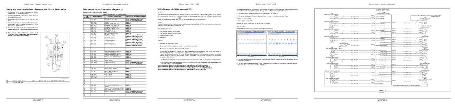
- Specifications, page 802: Hydraulic systems - Safety and main relief valves
- Diagram, page 1,222: Electrical systems - Harnesses and connectors
- Troubleshooting, page 1,522: 1063-Timeout of CAN message EEC2
- Color page, page 1,424: Electrical systems - FAULT CODES
- Foldout diagram (color), page 1,041: Electrical systems - Harnesses and connectors
Other manuals for this machine
Save 10% on 2 manuals, 15% on 3 or more. Other manuals for the U80C Tier 4B are listed below. Editions cover different serial number ranges: check the serial coverage and tick only the ones that match your machine.
Added to your cart. View cart
This is a service manual
Here's how it compares to the other manual types.
Service manual
Factory repair procedures and technical information such as specifications, troubleshooting, and wiring and hydraulic diagrams, for the models and systems the manual covers. See What's inside for its topics.
Operator's manual
Safe operation, controls, maintenance schedules, lubrication points, inspections, and basic checks. Repair procedures are in the service manual.
Parts manual
Illustrated diagrams with factory part numbers for identifying components and ordering parts. Repair procedures are in the service manual.
Engine service manuals are sometimes sold separately, since certain machine models were offered with more than one engine option.
What it's used for
Factory manual for in-house farm and construction shop use. Straightforward, complete, and easy to follow. It contains the OEM information dealership service departments and parts counters use to diagnose problems, identify components, and perform maintenance or repairs correctly.
Service shops and owner/operators who repair their own equipment
Identifying correct parts and seeing how assemblies come apart and go back together
Keeping equipment running with less downtime
Factory manual, 1,979 pages
Quantity one is the manual described above.
Fast free USA shipping
Ships in 1 business day.
60-day returns
Free if the mistake is ours. A manual ordered in error must come back unopened in its shrink-wrap; you pay return shipping and a 20% restocking fee applies. Return policy
Binder not included
Manuals over about 300 pages may need a standard 3-ring binder, which you can buy locally to keep the pages organized for shop use.
Other editions and similar models
Questions about model, serial number, engine coverage or contents? Contact us before purchasing and we'll help confirm it's the right manual. Please verify the manual type, machine model, serial number range and engine coverage before purchasing: manuals ordered in error carry a 20% restocking fee (return policy).