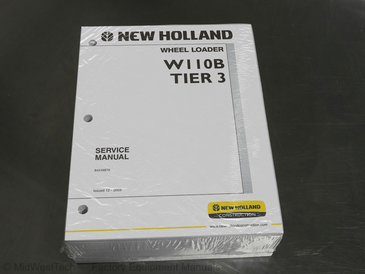
New Holland W110B Tier 3 Wheel Loader Service Manual
898 pages · Publication 84249879
Added to your cart. View cart
- Models
- W110B Tier 3
- Manual type
- Service Manual
- Pages
- 898
- Publication
- 84249879
- Condition
- Brand new
What's inside
From the manual's own table of contents: 373 topics. See sample pages (PDF, 630 KB)
- TORQUE SPECIFICATIONS - DECIMAL HARDWARE
- TORQUE SPECIFICATIONS - METRIC HARDWARE
- TORQUE SPECIFICATIONS - STEEL HYDRAULIC FITTINGS
- CAPACITIES AND LUBRICANTS
- ENGINE OIL RECOMMENDATIONS
- HYDRAULIC/BRAKE SYSTEM OIL TEMPERATURE CHART
- ENGINE OIL TEMPERATURE CHART
- TRANSMISSION OIL TEMPERATURE CHART
- DIESEL FUEL SYSTEM
- Fuel Storage
- Specifications for Acceptable No. 2 Diesel Fuel
- MAINTENANCE SCHEDULE
- Model W110B
- MAINTENANCE POINTS
- Engine
- Removal
- Installation
- RADIATOR
- SPECIFICATIONS
- Stall Speeds
- STALL TESTS
- INSTRUMENT CLUSTER DISPLAYS
- PROCEDURE TO HEAT THE OIL
- Torque Converter
Show all 373 topics
- Hydraulic System
- POWER MODE SELECTION
- PERFORMING STALL TESTS
- Test No. 1 - Torque Converter and Hydraulic Stall Together
- Understanding the Results of Test No. 1
- Test No. 2 - Torque Converter Stall
- Understanding the Results of Test No. 2
- Test No. 3 - Hydraulic Stall
- Understanding the Results of Test No. 3
- TROUBLESHOOTING AFTER COOLER
- AFTERCOOLER REMOVAL
- Leak Test
- STARTER
- ALTERNATOR
- BELT INSTALLATION
- With Out Air Conditioning
- With Air Conditioning
- ELECTRICAL WIRE IDENTIFICATION
- UNDERSTANDING THE TROUBLESHOOTING TABLES
- LOCATING COMPONENTS ON THE SCHEMATIC POSTERS
- STARTING AND CHARGING SYSTEMS
- Starting Relay
- Resistor
- Crank Control Relay
- Batteries
- Crank Request Relay
- Time Delay Module
- Master Disconnect Switch
- Starter Motor
- Ignition Switch
- Neutral Start Relay
- Voltmeter Relay
- POWER RELAY MODULES AND COLD STARTING SYSTEMS
- Power Relay Module A, Ignition Power
- Power Relay Module B, Ignition Power
- Power Relay Module C, For Fuel Filter Heater and Water Separator Heater
- Grid Heater Relay
- Grid Heater
- Circuit breaker Cab B+
- Water Separator Heater
- Fuel Filter Heater
- Power Relay Module D, Accessory Power
- ENGINE CONTROLLER
- Water In Fuel Sensor
- Throttle Potentiometer
- Electronic Diesel Control
- RETURN TO TRAVEL - RETURN TO DIG - PIN ENGAGE
- Return-To-Travel/Float Switch
- Height Control Switch
- Electromagnetic Detents
- Return-To-Dig Proximity Switch
- Pilot Control Relay
- Height Control/Return-To-Travel Proximity Switch
- Return to Dig Switch
- Pin Engage Switch (Option)
- Pilot Pressure Solenoid
- Pin Engage Solenoid (Option)
- PILOT CONTROL - RIDE CONTROL - FAN CONTROL
- Ride Control Switch
- Ride Control Relay
- Fan Reversing Switch (Option)
- Fan Reverse Relay
- Pilot Control Switch
- Ride Control Solenoid
- Rollback Pressure Switch (Option)
- Rollback Jumper (Option)
- Fan PWM Solenoid (Option)
- SAFETY RULES
- SPECIAL TOOLS
- MAINTENANCE
- Electrolyte Level
- Inspecting and Cleaning a Battery
- BATTERY TEST
- Visual Checks
- Specific Gravity Check
- Capacity (Load) Test
- CHARGING A BATTERY
- Charging Guide For Maintenance Free Batteries
- Charging Guide For Batteries Other Than Maintenance Free Batteries
- PREPARING A DRY CHARGED BATTERY FOR USE
- INSTRUMENT CLUSTER
- Self-Test
- Power Circuit Test
- LCD Multi-function Display
- Entering The Service Screens
- Clutch Calibration
- Options Menu
- RETRIEVING FAULT CODES
- General Fault Code Identification
- Fault Code Grouping
- LCD FAULT CODE DISPLAY BREAKDOWN
- VEHICLE FAULT CODES
- ENGINE FAULT CODES
- TRANSMISSION FAULT CODES
- INSTRUMENT CLUSTER FAULT CODES
- STEERING CONTROL VALVE
- AUXILIARY STEERING PRIORITY VALVE
- AUXILIARY STEERING PUMP AND MOTOR
- STEERING CYLINDER
- STEERING BACK PRESSURE VALVE
- TROUBLESHOOTING THE STEERING SYSTEM
- AUXILIARY STEERING SYSTEM PUMP TEST
- Equipment Required
- Test Procedure
- AUXILIARY STEERING SYSTEM MOTOR TEST
- Test Equipment
- UNDERSTANDING THE RESULTS OF THE TEST
- STEERING RELIEF VALVE
- Pressure Setting Test
- Pressure Setting Adjustment
- STEERING CYLINDER LEAK TEST
- Disassembly
- Inspection
- Assembly
- CENTER PIVOT
- CONNECTING THE FRONT FRAME TO THE REAR FRAME
- AUXILIARY STEERING MOTOR AND PUMP
- TRANSMISSION
- Transmission Mounting
- FRONT AXLE
- Front Axle Mounting
- REAR AXLE
- Rear Axle Mounting
- TRANSMISSION OPERATION
- General
- Transmission ECM
- Electrical Shift Solenoids
- Transmission ECM Tasks
- Transmission Sensor Data Collection
- Automatic Problem Modes
- Clutch Modulation Substitute Mode
- Limp-Home Mode
- Transmission/Transmission ECM Shutdown Mode
- Transmission Clutch Calibration
- Gear Selections
- Automatic/Manual Modes
- Upshifting in Automatic Mode
- Downshifting in Automatic Mode
- Upshifting in Manual Mode
- Downshifting in Manual Mode
- Downshift Button
- Automatic Mode
- Manual Mode
- Cold Start Protection System
- Brake Pedal Transmission Declutch
- TRANSMISSION PRESSURE TEST POINTS DIAGRAM
- CHART FOR RECORDING PRESSURE READINGS
- PRESSURE TEST RESULTS
- All or Most Pressures Low and/or Flow Test Low
- Some Pressures Low
- Not Enough Power
- Machine Stops or Hesitates While Shifting - Intermittent
- CONVERTER OUT PRESSURE CHECK
- Test Equipment Required
- LUBRICATION PRESSURE CHECK
- FLOWMETER TEST
- Flowmeter Test Procedure
- CONSUMPTION TEST PROCEDURE
- TRANSMISSION OVERHEATING
- ERROR CODES
- TRANSMISSION SHIFTER LOGIC INFORMATION
- RELATIONSHIP BETWEEN TRANSMISSION ECM, VALVES, AND CLUTCHES
- SPECIAL TORQUES
- SPECIAL TORQUES (continued)
- GEAR TOOTH CONTACT PATTERNS
- LUBRICATION
- WEAR MEASUREMENT ON MULTI-DISC BRAKE
- WHEEL END AND BRAKE
- Cleaning and Inspection
- BRAKE HYDRAULICS LEAKAGE TEST
- High Pressure Test
- Low Pressure Test
- REPLACing HUB SEAL
- DIFFERENTIAL
- Drive Pinion Removal
- Brake Tube Removal
- Brake Tube Installation
- Drive Pinion Installation
- Drive Pinion Bearing Rolling Torque Adjustment
- Setting Backlash and Bearing Preload
- Contact Pattern Check
- FRONT DRIVE SHAFT
- CENTER BEARING
- CENTER DRIVE SHAFT
- REAR DRIVE SHAFT
- ENGINE DRIVE SHAFT
- UNIVERSAL JOINTS
- WHEELS AND BOLTS
- General Information
- Torque Specification
- TIRE PRESSURES
- CHANGING TIRES
- INSTALLING A WHEEL
- Control Valve
- BRAKE VALVE
- SERVICE BRAKE AND PARKING BRAKE ACCUMULATORS
- BRAKE PUMP
- TROUBLESHOOTING THE HYDRAULIC BRAKE SYSTEM
- BLEEDING THE BRAKE SYSTEM
- BRAKE MODULATION PRESSURE CHECK
- Testing the Brake Modulation Pressure
- Adjusting the Brake Modulation Pressure
- SERVICE BRAKE SYSTEM PERFORMANCE (STORED ENERGY)
- BRAKE PUMP OUTPUT TEST
- Brake Valve Exploded View
- ACCUMULATOR SPECIAL TORQUES
- CHECKING THE NITROGEN CHARGE IN THE ACCUMULATOR
- DISCHARGING THE NITROGEN CHARGE ON AN ACCUMULATOR
- CHARGING THE ACCUMULATOR WITH DRY NITROGEN
- PARKING BRAKE
- Parking Brake Adjustment Procedure
- STATIC PARKING BRAKE TEST PROCEDURE
- Dynamic Parking Brake Test
- Parking Brake Disable Procedure
- HOW TO READ SYMBOLS IN A HYDRAULIC SCHEMATIC
- Introduction
- Circuit Diagrams
- Symbol Systems
- Using Schematic Symbols
- Lines, Tubes, and Hoses
- Crossing or Joining Lines
- Pump Symbols
- Hydraulic Motor Symbols
- Cylinder Symbols
- Pressure Control Symbols
- Directional Control Symbols
- Composite Symbols
- Flow Control Symbols
- Accessories
- SIMPLE SCHEMATIC
- COMMON SYMBOLS
- Line and Line Fuctions
- Mechanical Devices
- Pumps and Motors
- Reservoirs
- Cylinders
- Valves
- Valve Actuators
- LOADER CONTROL VALVE
- spool line removal and installation illustration
- REMOTE CONTROL VALVE
- Joystick and 2 Lever Hose Color Coding
- Joystick and 1 Lever Hose Color Coding
- Lever Hose Color Coding
- Joystick Hose Color Coding
- lever Hose Color Coding
- HYDRAULIC PUMP
- LIFT CYLINDERS
- BUCKET CYLINDER - Z-BAR LOADER
- Z-bar Loader Bucket Cylinder Removal And Installation Illustration
- BUCKET CYLINDERS - TC LOADER
- TC Loader Bucket Cylinder Removal And Installation Illustration
- OIL COOLER
- LOAD TRAVEL STABILIZATION ACCUMULATOR
- LOAD TRAVEL STABILIZATION VALVE
- FAN REVERSING VALVE
- THERMAL VALVE
- TROUBLESHOOTING PROCEDURE
- Problem in all Circuits
- Problem in all Loader Circuits
- Problem in the Braking Circuit
- Problem in a Single Loader Circuit
- Problem in the Steering Circuit
- Problem in the Load Travel Stabilization
- TESTING AND ADJUSTING THE PUMP DIFFERENTIAL PRESSURE
- Pressure Check
- Adjusting the Main Hydraulic Pump
- TESTING AND ADJUSTING THE MAIN RELIEF VALVE
- Adjustment
- TESTING THE PILOT PRESSURE
- TESTING AND ADJUSTING THE CIRCUIT RELIEF VALVES
- TESTING THE LOAD TRAVEL STABILIZATION
- HYDRAULIC COMPONENT LOCATIONS
- TYPES OF CONTAMINATION
- CLEANING THE HYDRAULIC SYSTEM
- FLUSHING WATER FROM THE HYDRAULIC SYSTEM
- Spool Valve Housing Configuration
- Spool Valve Spool Configuration
- Spool Mounting Configuration
- and 4 Spool Valve Spool Configuration
- Circuit Relief
- Pressure Test
- LIFT CYLINDER
- BUCKET CYLINDERS Z-BAR MODELS
- BUCKET CYLINDERS FOR TC MODELS
- Z-BAR AND TC MODELS
- REPLACING BUSHINGS FOR THE BUCKET CYLINDER Z-BAR MODELS
- REPLACING BUSHINGS FOR THE BUCKET CYLINDERS TC MODELS
- COUPLER SOLENOID LOCKING VALVE
- TESTING RIDE CONTROL
- Checking Nitrogen Charge On Accumulator
- Charging Accumulator With Nitrogen
- Dissasembly
- SAFETY PROCEDURES
- OPERATION
- TROUBLESHOOTING
- Problem: No Cooling
- SYSTEM CHECKS
- Mechanical Compressor Check
- Blower and Compressor Clutch Check
- Cab Temperature Check
- Visual and Leak Check
- Evaporator/Heater Core Check
- Evaporator/Heater Core
- PRESSURE TESTING
- Manifold Gauge Set
- Pressure Test Connection
- PRESSURE-TEMPERATURE CHART
- QUICK REFERENCE TROUBLESHOOTING CHART
- A/C RECOVERY AND CHARGING STATION CONNECTIONS
- Indication of No Refrigerant or Low Refrigerant Charge
- Indication of Large Quantity of Air in System
- Condenser Malfunctioning - Indications
- Expansion Valve Malfunctioning - Indications
- Refrigerant Contamination
- HFC-134a Stable Saturation Pressure/ Temperature Chart
- PROBLEM: NOT ENOUGH COOLING
- Air in the System - Indications
- Not Enough Refrigerant - Indications
- High Side Restriction - Indications
- Expansion Valve Not Operating - Indications
- Compressor Turning But Not Pumping Properly - Indications
- Expansion Valve Stuck Open
- Condenser Not Operating - Indications
- PROBLEM: INTERMITTENT COOLING
- Moisture in the System - Indications
- PROBLEM: NOISE IN SYSTEM
- Too Much Refrigerant in System - Indications
- TUBE CONNECTIONS TORQUE CHART
- AIR CONDITIONER SYSTEM REFRIGERANT RECOVERY
- AIR CONDITIONER SYSTEM EVACUATION AND RECHARGING
- PRESSURE - TEMPERATURE CHART
- COMPRESSOR
- HEATER VALVE, BLOWERS
- CONDENSER AND RECIEVER DRIER
- BUCKET TEETH
- Replacement of the Tooth Points
- Replacement of the Bucket Teeth
- Replacement of the Bucket Corner Teeth
- RETURN TO DIG ADJUSTMENT (Z-BAR AND LR MODELS)
- RETURN TO DIG ADJUSTMENT (TC MODELS)
- (Z-BAR, TC, AND LR MODELS)
- LOADER FRAME (Z-BAR AND LR MODELS)
- Remove
- Install
- LOADER FRAME (TC MODELS)
- CAB STRUCTURAL FRAME (CSF)
- MAINTENANCE AND INSPECTION OF THE (CSF) CAB OR (ROPS) CANOPY
- CSF CAB AND ROPS CANOPY
Inside this manual
Real pages from this service manual (898 pages). Open the sample pages (PDF, 629 KB)

- Troubleshooting, page 441: ERROR CODES
- Specifications, page 506: BRAKE HYDRAULICS LEAKAGE TEST
- Diagram, page 740: HYDRAULIC COMPONENT LOCATIONS
- Foldout diagram (color): SEE NOTE 2
Other manuals for this machine
Save 10% on 2 manuals, 15% on 3 or more. Other manuals for the W110B Tier 3 are listed below. Editions cover different serial number ranges: check the serial coverage and tick only the ones that match your machine.
Added to your cart. View cart
This is a service manual
Here's how it compares to the other manual types.
Service manual
Factory repair procedures and technical information such as specifications, troubleshooting, and wiring and hydraulic diagrams, for the models and systems the manual covers. See What's inside for its topics.
Operator's manual
Safe operation, controls, maintenance schedules, lubrication points, inspections, and basic checks. Repair procedures are in the service manual.
Parts manual
Illustrated diagrams with factory part numbers for identifying components and ordering parts. Repair procedures are in the service manual.
Engine service manuals are sometimes sold separately, since certain machine models were offered with more than one engine option.
What it's used for
Factory manual for in-house farm and construction shop use. Straightforward, complete, and easy to follow. It contains the OEM information dealership service departments and parts counters use to diagnose problems, identify components, and perform maintenance or repairs correctly.
Service shops and owner/operators who repair their own equipment
Identifying correct parts and seeing how assemblies come apart and go back together
Keeping equipment running with less downtime
Factory manual, 898 pages
Quantity one is the manual described above.
Fast free USA shipping
Ships in 1 business day.
60-day returns
Free if the mistake is ours. A manual ordered in error must come back unopened in its shrink-wrap; you pay return shipping and a 20% restocking fee applies. Return policy
Binder not included
Manuals over about 300 pages may need a standard 3-ring binder, which you can buy locally to keep the pages organized for shop use.
Questions about model, serial number, engine coverage or contents? Contact us before purchasing and we'll help confirm it's the right manual. Please verify the manual type, machine model, serial number range and engine coverage before purchasing: manuals ordered in error carry a 20% restocking fee (return policy).