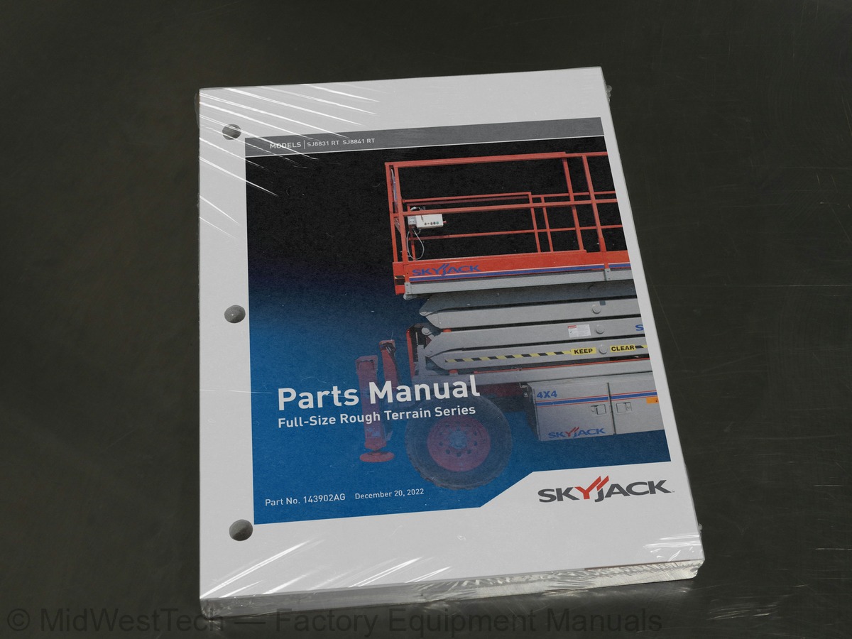
Skyjack SJ8831 RT, SJ8841 RT Rough Terrain Scissor Lift Parts Manual
217 pages · Publication 143902AG
Added to your cart. View cart
What's inside
From the manual's own table of contents: 8 sections, 106 entries. See sample pages (PDF, 484 KB)
Platform Related Parts14 topics
- Figure 1.1 Main Platform And Railings
- Figure 1.2 4 Ft. Roll-out Extension Platform Assembly
- Figure 1.3 4 Ft. Powered Extension Platform Assembly
- Figure 1.4 Powered Extension Platform Control Console Assembly
- Figure 1.5 Powered Extension Platform Cylinder Assembly
- Figure 1.6 Powered Extension Platform Electrical Panel
- Figure 1.7 Hydraulic Hose Connections - Single Powered Extension Platform
- Figure 1.8 Hydraulic Hose Connections - Dual Powered Extension Platforms (Model 8831)
- Figure 1.9 Hydraulic Hose Connections - Dual Powered Extension Platforms (Model 8841)
- Figure 1.10 Safety D-ring Assembly
- Figure 1.11 Platform Control Console Assembly - Hardware
- Figure 1.12 Platform Control Console Assembly - Switches
- Figure 1.13 Drive/Steer Controller Assembly
- Figure 1.14 Control Cable Assemblies
Scissor Related Parts10 topics
- Figure 2.1 Scissor Arm Assembly - Model 8831
- Figure 2.2 Scissor Arm Assembly - Model 8841
- Figure 2.3 Scissor Stack Mounting Hardware Assemblies
- Figure 2.4 Scissor Arm Connecting Hardware Assemblies
- Figure 2.5 Horn, Light & Beeper Assemblies (ANSI/CSA)
- Figure 2.6 Horn, Light, Beeper, & Load Sensing Assemblies (CE)
- Figure 2.7 Lift Cylinder Assembly
- Figure 2.8 Hydraulic Hose Connections- Scissors
- Figure 2.9 Lift Cylinder Holding Valve Manifold Assembly
- Figure 2.10 Lift Cylinder Holding Valve Manifold Assembly with Transducer (CE)
Base Related Parts13 topics
- Figure 3.1 Base, Axles And Wheels
- Figure 3.2 Hydraulic Hose Connections - Base (Cushman/Dana Axles)
- Figure 3.3 Fuel/Tank Hydraulic Oil Tank Cabinet Assembly
- Figure 3.4 Hydraulic Oil Tank Assembly
- Figure 3.5 Fuel Tank Assembly
- Figure 3.6 Hydraulic/Electric Cabinet Assembly
- Figure 3.7 Hydraulic Hose Connections - Cabinet Assembly
- Figure 3.8 Auto Reset Brake Manifold Assembly
- Figure 3.9 Motion Control Valve System
- Figure 3.10 Main Manifold Assembly
- Figure 3.11 Base Control/Electrical Panel Assembly
- Figure 3.12 Base Control/Electrical Panel Harnesses
- Figure 3.13 Base Control Console Assembly
Axle Related Parts20 topics
- Figure 4.1 Front Idle Axle Assembly (For 2-wheel Drive Aerial platforms)
- Figure 4.2 Front Axle Hardware Assembly - All Wheel Drive Option (Cushman Axles)
- Figure 4.3 Front Axle Assembly - All Wheel Drive Option (Cushman Axles)
- Figure 4.4 Front Axle Assembly (Axle End) - All Wheel Drive Option (Cushman Axles)
- Figure 4.5 Front Axle (Differential Assembly) - All Wheel Drive Option (Cushman Axles)
- Figure 4.6 Front & Rear Axle (Wheel Hub Assembly) - All Wheel Drive Option (Cushman Axles)
- Figure 4.7 Front Axle (Axle Shaft Assembly) - All Wheel Drive Option (Cushman Axles)
- Figure 4.8 Steer Cylinder Assembly (4WD / Cushman Front Axle - 4WD) (Cushman Axles)
- Figure 4.9 Front Axle Assembly (For 4-wheel Drive Aerial platforms) (Dana Axles)
- Figure 4.10 Front Drive Axle Assembly - 4-wheel Drive (Dana Axles)
- Figure 4.11 Steer Cylinder Assembly (Dana Axles)
- Figure 4.13 Drive Motor Assembly
- Figure 4.12 Drive Shaft Assembly
- Figure 4.14 Center Drive Assembly
- Figure 4.15 Rear Axle Assembly - (Cushman Axles)
- Figure 4.16 Rear Axle (Differential Assembly) - (Cushman Axles)
- Figure 4.17 Rear Axle (Brake Assembly) - (Cushman Axles)
- Figure 4.18 Rear Drive Axle Assembly (Dana Axles)
- Figure 4.19 Disc Brake Assembly (Dana Axles)
- Figure 4.20 Disc Brake Cylinder Assembly (Dana Axles)
Engine Related Parts14 topics
- Figure 5.1 Engine Roll Out Tray & Cover Assembly
- Figure 5.2 Engine Control Panel
- Figure 5.3 Engine Tray Lock Assembly
- Figure 5.4 Diesel Engine Assembly (Kubota Diesel Engine D1305)
- Figure 5.5 Diesel Fuel System (Kubota Diesel Engine D1305)
- Figure 5.6 Kubota Diesel Fuel Engine Harness
- Figure 5.7 Air Intake Assembly (Kubota Diesel Engine D1305)
- Figure 5.8 Hydraulic Pump Assembly
- Figure 5.9 Exhaust Manifold Assembly (Kubota Diesel Engine D1305)
- Figure 5.10 Engine Roll Out Accessories (GM Dual Fuel Engine)
- Figure 5.11 Dual Fuel Engine Assembly (GM Dual Fuel Engine)
- Figure 5.12 Bell Housing Assembly (GM Dual Fuel Engine)
- Figure 5.13 Engine Interface Harness (GM Dual Fuel Engine)
- Figure 5.14 Dual Fuel Hose Assembly (GM Dual Fuel Engine)
Optional Equipment22 topics
- Figure 6.1 Hydraulic Outrigger Option - Hydraulic Hose Connections
- Figure 6.2 Hydraulic Outrigger Option - Leg Assembly
- Figure 6.3 Hydraulic Outrigger Option - Cylinder Assembly
- Figure 6.4 Hydraulic Outrigger Option - Manifold Assembly
- Figure 6.5 Hydraulic Outrigger Option - Electrical Panel Assembly
- Figure 6.6 Hydraulic Outrigger Option (Auto level) - Electrical Panel Connections
- Figure 6.7 GP-108 Controller
- Figure 6.8 Flashing Light Relay Harness
- Figure 6.9 Outrigger/Hydraulic Generator Control Console Assembly
- Figure 6.10 3500 Hydraulic Generator & Oil Cooler Option
- Figure 6.11 12kW Hydraulic Generator & Oil Cooler Option
- Figure 6.12 Hydraulic Generator & Oil Cooler Assembly
- Figure 6.13 12kW Generator Mount & Breaker Box Assembly
- Figure 6.14 Hydraulic Connections - 12kW Generator
- Figure 6.15 Hydraulic Valve Assembly - 12kW Generator
- Figure 6.16 Welder Option (ANSI/CSA)
- Figure 6.17 1500W Inverter Option
- Figure 6.18 Load Sensing Components (CE)
- Figure 6.19 Air Hose to Platform Option
- Figure 6.20 Work Light Option
- Figure 6.21 Platform AC Outlet
- Figure 6.22 Scissor Guard Option
Labels5 topics
- Figure 7.1 Label Kit
- Figure 7.2 Labels And Nameplates - Misc
- Figure 7.3 Labels And Nameplates - Control Console Assemblies
- Figure 7.4 Labels And Nameplates
- Figure 7.5 Labels - Outrigger
Inside this manual
Real pages from this parts manual (217 pages). Open the sample pages (PDF, 483 KB)
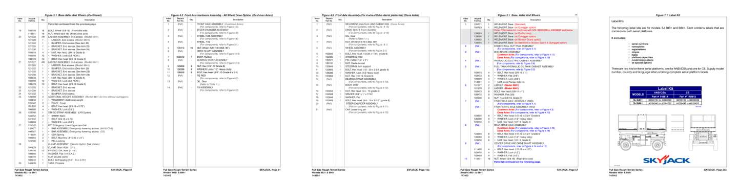
- Parts illustration, page 62: SKYJACK, Page 61
- Parts illustration, page 92: SKYJACK, Page 91
- Parts illustration, page 104: SKYJACK, Page 103
- Color page, page 58: SKYJACK, Page 57
- Color page, page 204: SKYJACK, Page 203
Other manuals for this machine
Save 10% on 2 manuals, 15% on 3 or more. Other manuals for the SJ8831 RT, SJ8841 RT are listed below. Editions cover different serial number ranges: check the serial coverage and tick only the ones that match your machine.
Added to your cart. View cart
This is a parts manual
Here's how it compares to the other manual types.
Service manual
Factory repair procedures and technical information such as specifications, troubleshooting, and wiring and hydraulic diagrams, for the models and systems the manual covers. See What's inside for its topics.
Operator's manual
Safe operation, controls, maintenance schedules, lubrication points, inspections, and basic checks. Repair procedures are in the service manual.
Parts manual
Illustrated diagrams with factory part numbers for identifying components and ordering parts. Repair procedures are in the service manual.
What it's used for
Factory manual for in-house farm and construction shop use. Straightforward, complete, and easy to follow. It contains the OEM information dealership service departments and parts counters use to diagnose problems, identify components, and perform maintenance or repairs correctly.
Service shops and owner/operators who repair their own equipment
Identifying correct parts and seeing how assemblies come apart and go back together
Keeping equipment running with less downtime
Factory manual, 217 pages
Quantity one is the manual described above.
Fast free USA shipping
Ships in 1 business day.
60-day returns
Free if the mistake is ours. A manual ordered in error must come back unopened in its shrink-wrap; you pay return shipping and a 20% restocking fee applies. Return policy
Other editions and similar models
Questions about model, serial number, engine coverage or contents? Contact us before purchasing and we'll help confirm it's the right manual. Please verify the manual type, machine model, serial number range and engine coverage before purchasing: manuals ordered in error carry a 20% restocking fee (return policy).