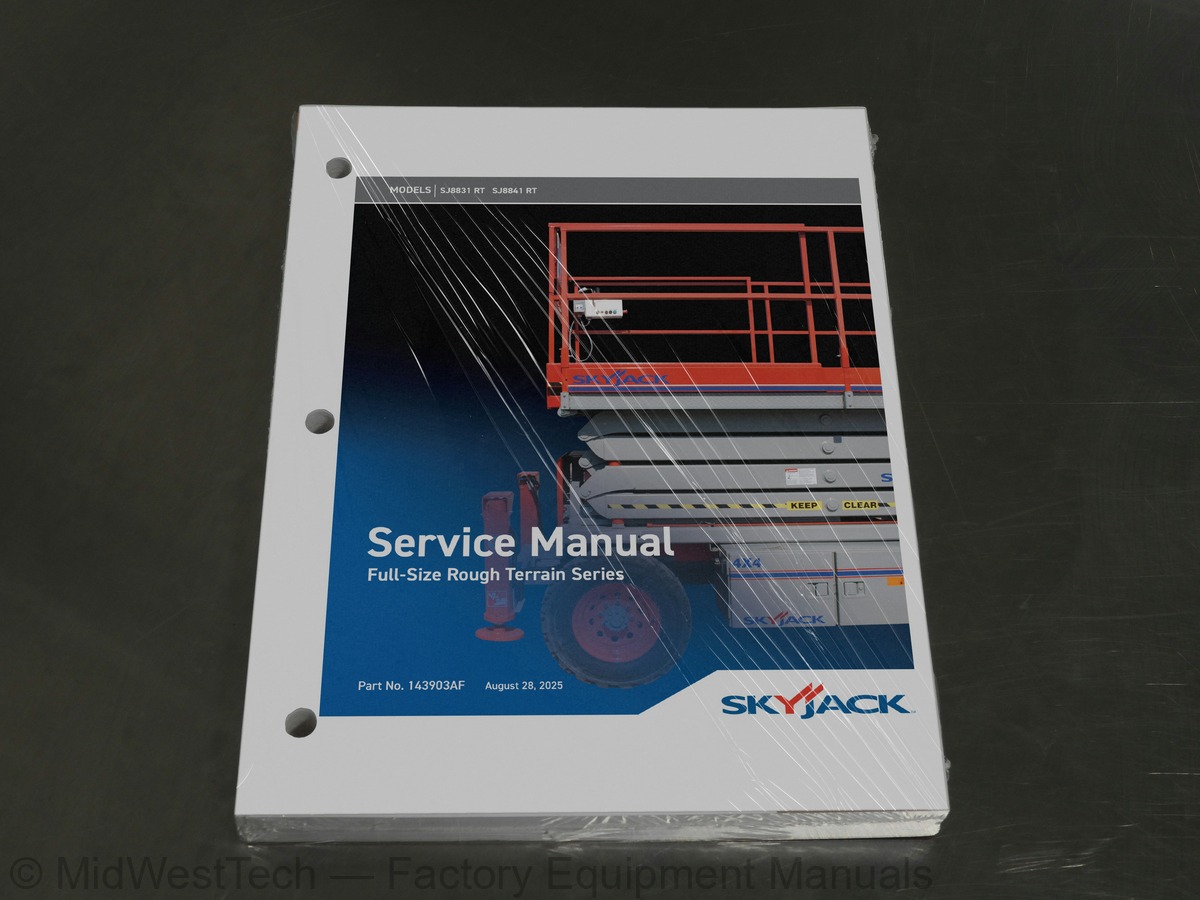
Skyjack SJ8831 RT, SJ8841 RT Rough Terrain Scissor Lift Service Manual
205 pages · Publication 143903AF
Added to your cart. View cart
What's inside
From the manual's own table of contents: 5 sections, 246 entries. See sample pages (PDF, 547 KB)
Operator’s Responsibility for Maintenance30 topics
- Aerial Platform Definition
- Purpose of Equipment
- Use of Equipment
- Manuals
- Operating
- Service & Maintenance
- Operator
- Service Policy and Warranty
- Optional Accessories
- Scope of this Manual
- Operator Safety Reminders
- Electrocution Hazard
- Safety Precautions
- Maintenance and Inspection Schedule
- Owner’s Annual Inspection Record
- Replacement Parts
- Maintenance and Service Safety Tips
- Hydraulic System & Component Maintenance and Repair
- Maintenance Hints
- Railing Maintenance and Repair
- Service and Maintenance
- About this Section
- Service Bulletins
- Maintenance and Inspection
- Maintenance Instructions
- Table 1.1 Owner’s Annual Inspection Record
- Table 1.2 Maintenance and Inspection Checklist
- Scheduled Maintenance
- Scheduled Maintenance Inspections
- Function Tests
Section 2 - Maintenance Tables and Diagrams17 topics
- Table 2.1a Specifications and Features - ANSI/CSA
- Table 2.1b Specifications and Features - CE
- Table 2.1c Specifications and Features - AS
- Table 2.2a Maximum Platform Capacities (Evenly Distributed) - ANSI/CSA
- Table 2.2b Maximum Platform Capacities (Evenly Distributed w/ Optional #7 Tires) - ANSI/CSA
- Table 2.2c Maximum Platform Capacities (Evenly Distributed) - CE
- Table 2.2d Maximum Platform Capacities (Evenly Distributed) - AS
- Table 2.3a Tire Specifications - ANSI/CSA
- Table 2.3b Tire Specifications - CE
- Table 2.3c Tire Specifications - AS
- Floor Loading Pressure
- Table 2.4a Floor Loading Pressure - ANSI/CSA
- Table 2.4b Floor Loading Pressure - CE
- Table 2.4c Floor Loading Pressure - AS
- Table 2.5 Rough Terrain Scissor Fluids
- Table 2.5 Rough Terrain Scissor Fluids (Continued)
- Table 2.6 Torque Specifications
Section 3 - System Component Identification and Schematics38 topics
- Hydraulic Symbol Chart
- Charts
- Electrical Symbol Chart
- Hydraulic Parts List
- Parts List
- Electrical Parts List
- Diagrams and Schematics
- Platform Control Console Diagram - With All Options (ANSI/CSA & AS)
- Platform Control Console Diagram - With All Options (CE)
- Control Cable Assemblies Diagram
- Outrigger/Hydraulic Generator Control Console Wiring
- Main Manifold Components & Port Identifications
- Hydraulic Manifold Components & Port Identifications
- Hydraulic Schematic
- Main Manifold Wiring Diagram (ANSI/CSA & AS)
- Main Manifold Wiring Diagram (CE)
- Horn, Light, Beeper Wiring Diagram (ANSI/CSA and AS)
- Horn, Light, Beeper & Load Sensing Wiring Diagram (CE)
- Powered Extension Platform - Electrical Connection Diagram
- Engine Harness Wiring Diagram - Kubota Diesel Engine
- Engine Harness Wiring Diagram - GM Dual Fuel Engine
- Electrical Panel Diagram - ANSI/CSA & AS
- Electrical Panel Diagram - CE
- Electrical Schematic - Kubota Diesel Engine (ANSI/CSA & AS - All Options)
- Electrical Schematic - Kubota Diesel Engine (ANSI/CSA & AS - Welder Option)
- Electrical Schematic - Kubota Diesel Engine (CE - All Options)
- Electrical Schematic - GM Dual Fuel Engine (ANSI/CSA & AS - No Options)
- Electrical Schematic - GM Dual Fuel Engine (ANSI/CSA & AS - All Options)
- Interface & Engine Electrical Schematic - GM Dual Fuel Engine
- Electrical Panel Diagram - Outrigger Option
- Outrigger Connection Diagram
- Oil Cooler Electrical Panel Diagram
- Hydraulic Generator Electrical Panel Diagram (Kubota Engine) ANSI/CSA & AS
- Hydraulic Generator Electrical Panel Diagram (Kubota Engine) (CE)
- Electrical Panel Diagram - 12kW Generator Modification (ANSI/CSA)
- 3.33 12kW Generator Hydraulic and Electric Wiring Schematics (ANSI/CSA)
- Electrical Inverter Wiring Diagram
- Flashing Light Relay Harness
Section 4 - Troubleshooting Information108 topics
- Introduction
- Electrical System
- 4.1-1 All Controls Inoperative
- 4.1-2 No Power to Platform (ANSI/CSA)
- 4.1-3 No Power to Platform (CE)
- 4.1-4 All Functions Inoperative from Platform
- 4.1-5 Engine will Not Crank from Platform
- 4.1-6 Engine will Not Crank from Platform Controls (Additional for GM Dual Fuel)
- 4.1-7 Engine will Not Crank from Base Controls (GM dual fuel)
- 4.1-8 Engine will Not Crank from Base Controls (Kubota diesel)
- 4.1-9 Engine Cranks but Stops Cranking after a few seconds
- 4.1-10 Glow Plugs Inoperative from Engine Controls
- 4.1-11 Glow Plugs Inoperative from Platform (Additional)
- 4.1-12 Engine Cranks but will Not Start (Kubota diesel)
- 4.1-13 Engine Cranks but will Not Start (GM dual fuel)
- 4.1-14 Mid Throttle Inoperative (on demand) (GM Dual Fuel)
- 4.1-15 High Throttle Inoperative
- 4.1-16 High Throttle Inoperative (additional for GM dual fuel)
- 4.1-17 Drive and Steer Inoperative (Machines without outriggers option)
- 4.1-18 Drive and Steer Inoperative (machines with outriggers option)
- 4.1-19 Brakes will Not Release
- 4.1-20 Steer Right Inoperative
- 4.1-21 Steer Left Inoperative
- 4.1-22 Reverse Drive Inoperative
- 4.1-23 Forward Drive Inoperative
- 4.1-24 First Drive Speed and Steering Inoperative
- 4.1-25 Second Drive Speed Inoperative
- 4.1-26 Third Drive Speed Inoperative
- 4.1-27 High/Low Range Speed Inoperative
- 4.1-28 Up Circuit Inoperative from Platform or Base (machines without outriggers)
- 4.1-29 Up Circuit Inoperative from Base (ANSI/CSA)
- 4.1-30 Up Circuit Inoperative from Base (CE)
- 4.1-31 Platform will Not Lift from Platform or Base Controls with Outriggers Retracted (lift operates correctly with out
- 4.1-32 Platform will Not Lift from Platform or Base Controls with Outriggers Extended
- 4.1-33 Down Circuit Inoperative from Platform or Base
- 4.1-34 Down Circuit Inoperative from Base (ANSI/CSA)
- 4.1-35 Down Circuit Inoperative from Base (CE)
- 4.1-36 Powered Extension Platform Inoperative
- 4.1-37 Powered Extension Platform will Not Extend
- 4.1-38 Powered Extension Platform will Not Retract
- 4.1-39 Hydraulic Generator Inoperative
- 4.1-40 Hydraulic Generator will Not Shut Off from Generator Switch
- 4.1-41 All Outriggers Inoperative (Auto-level and manual)
- 4.1-42 All Outriggers Inoperative (Auto-level and manual from platform controls)
- 4.1-43 All Outriggers Inoperative (Base controls)
- 4.1-44 All Outriggers Inoperative (Auto-level) A: Led Power Indicator Light at Outrigger Control Module (OCM1) Not on Co
- 4.1-45 All Outriggers Inoperative (Auto Level Only) B: Led Power Indicator Light at Outrigger Control Module (OCM1) Flas
- 4.1-46 Left Front Outrigger Inoperative Manually
- 4.1-47 Right Front Outrigger Inoperative Manually
- 4.1-48 Right Rear Outriggers Inoperative Manually
- 4.1-49 Left Rear Outriggers Inoperative Manually
- 4.1-50 Individual Outrigger Functions Inoperative (auto-level)
- 4.1-51 Auto-level Inoperative
- 4.1-52 Auto All Up Inoperative (Retract)
- Hydraulic System
- 4.2-1 All Functions Inoperative
- 4.2-2 Steering Inoperative
- 4.2-3 Steer and First Drive Speed Inoperative
- 4.2-4 Lift and Second Drive Speed Inoperative
- 4.2-5 Drive Inoperative
- 4.2-6 Reverse Drive Inoperative
- 4.2-7 Forward Drive Inoperative
- 4.2-8 Brakes will Not Release
- 4.2-9 Brakes will Not Release (Internal Brake)
- 4.2-10 Brake Slips (Internal Brake)
- 4.2-11 Brake Drags or Runs Hot (Internal Brake)
- 4.2-12 Up Circuit Inoperative
- 4.2-13 Down Circuit Inoperative
- 4.2-14 Powered Extension Platform Inoperative
- 4.2-15 Hydraulic Generator Inoperative
- 4.2-16 All Outriggers Inoperative
- 4.2-17 Left Front Outrigger Inoperative
- 4.2-18 Right Front Outrigger Inoperative
- 4.2-19 Right Rear Outrigger Inoperative
- 4.2-20 Left Rear Outrigger Inoperative
- 4.2-21 Outriggers Drift In
- 4.3-1 Flash Code F01: Check HWFS
- 4.3-2 Flash Code F02: Not Ground Mode
- 4.3-3 Flash Code F03: Not Stopped
- 4.3-4 Flash Code F04: Tilted
- 4.3-5 Flash Code F05: Bad Height
- 4.3-6 Flash Code F06: Check Elev
- 4.3-7 Flash Code F08: Check Elev
- 4.3-8 Flash Code F09: Bad Height
- 4.3-9 Flash Code F10: Bad Height
- Load Sensing System - CE
- 4.3-12 Flash Code F13: Low Height Range
- 4.3-13 Flash Code F14: Bad Height
- 4.3-14 Flash Code F15: Check Elev
- 4.3-15 Flash Code F16: Low Elev.open
- 4.3-16 Flash Code F17: High Elev.open
- 4.3-17 Flash Code F18: Low Elev.close
- 4.3-18 Flash Code F19: High Elev.close
- 4.3-24 Flash Code F25: Check Elev
- 4.3-25 Flash Code F26: Check Elev
- 4.3-26 Flash Code F27: Bad Height
- 4.3-27 Flash Code F30: Bad Heights
- 4.3-28 Flash Code F31: Reject Curve
- 4.3-29 Flash Code F32: Reject Curve
- 4.3-30 Flash Code F33: Reject Curve
- 4.3-31 Flash Code F34: Reject Curve
- 4.3-32 Flash Code F40: Reject Delta
- 4.3-33 Flash Code F42: Low Pressure
- 4.3-34 Flash Code F43: High Pressure
- 4.3-35 Flash Code F44: Low Pressure
- 4.3-36 Flash Code F45: High Pressure
- 4.3-37 Flash Code F46: Check Elev
- 4.3-38 Flash Code F47: Check Elev
Section 5 - Procedures48 topics
- General
- Safety and workmanship
- Engine
- 5.1-1 Kubota dual fuel (DF972) resistance checks
- 5.1-2 ECU Pin reference chart (GM)
- 5.1-3 Throttle actuator (GM)
- 5.1-4 GM Map and IAT sensor (GM)
- 5.1-5 Engine coolant temperature sensor (GM)
- 5.1-6 LPG Temperature sensor (GM)
- 5.1-7 Fuse block layout (GM)
- Base
- 5.2-1 Torque the wheel bolts and nuts
- 5.2-2 Install and torque the wheels
- 5.2-3 Electronic tilt switch setup procedure
- 5.2-4 Front axle hub procedure
- Hydraulics
- 5.3-1 Hydraulic system and brake adjustment procedure (if equipped)
- 5.3-2 Brake assembly and disassembly (if equipped)
- 5.3-3 Multiple disc brake assembly diagram
- 5.3-4 Holding torque testing procedure
- 5.3-5 Adjust the system lift and pressure
- 5.3-6 Change the hydraulic oil
- Outriggers
- 5.4-1 Outrigger mechanical limit switch wiring diagram
- Control Modules Identification
- 5.5-1 Identification
- EZcal Diagnostic Tool
- 5.6-1 Hand held EZcal calibration and diagnostic tool key functions
- 5.6-2 Flash the controller
- 5.6-3 Outrigger codes
- 5.6-4 Curve/group codes
- Auto-leveling Outrigger PC Board
- 5.7-1 Auto-leveling outrigger PC board layout
- GP-102 (CM1) Control Module
- 5.8-1 Set up the GP-102 load sense controller
- 5.8-2 GP-102 Load sense controller pin reference table
- 5.8-3 LED Error codes - quick reference chart
- 5.8-4 LED Error codes - code breakdown chart
- 5.8-5 Control module load calibration - code messages & definitions
- GP-106 (OCM1) Control Module
- 5.9-1 Outrigger control module (GP-106/OCM1) instructions
- 5.9-2 Auto-leveling outrigger setting and error codes
- 5.9-3 Auto-leveling outrigger error code breakdown
- 5.9-4 Set up the GP-106 outrigger controller
- 5.9-5 GP-106 Outrigger controller pin reference table
- GP-108 Control Module
- 5.10-1 Set up the GP-108 overload/outrigger controller
- 5.10-2 GP-108 Overload/outrigger controller pin reference table
Inside this manual
Real pages from this service manual (205 pages). Open the sample pages (PDF, 546 KB)

- Specifications, page 47: SKYJACK, Page 46
- Diagram, page 83: SKYJACK, Page 82
- Troubleshooting, page 134: SKYJACK, Page 133
- Color page, page 49: SKYJACK, Page 48
- Color page, page 106: Full-Size Rough Terrain Series
- Foldout diagram (color), page 102: SKYJACK, Page 101
Other manuals for this machine
Save 10% on 2 manuals, 15% on 3 or more. Other manuals are listed below. Editions cover different serial number ranges: check the serial coverage and tick only the ones that match your machine.
Added to your cart. View cart
This is a service manual
Here's how it compares to the other manual types.
Service manual
Factory repair procedures and technical information such as specifications, troubleshooting, and wiring and hydraulic diagrams, for the models and systems the manual covers. See What's inside for its topics.
Operator's manual
Safe operation, controls, maintenance schedules, lubrication points, inspections, and basic checks. Repair procedures are in the service manual.
Parts manual
Illustrated diagrams with factory part numbers for identifying components and ordering parts. Repair procedures are in the service manual.
Engine service manuals are sometimes sold separately, since certain machine models were offered with more than one engine option.
What it's used for
Factory manual for in-house farm and construction shop use. Straightforward, complete, and easy to follow. It contains the OEM information dealership service departments and parts counters use to diagnose problems, identify components, and perform maintenance or repairs correctly.
Service shops and owner/operators who repair their own equipment
Identifying correct parts and seeing how assemblies come apart and go back together
Keeping equipment running with less downtime
Factory manual, 205 pages
Quantity one is the manual described above.
Fast free USA shipping
Ships in 1 business day.
60-day returns
Free if the mistake is ours. A manual ordered in error must come back unopened in its shrink-wrap; you pay return shipping and a 20% restocking fee applies. Return policy
Other editions and similar models
Questions about model, serial number, engine coverage or contents? Contact us before purchasing and we'll help confirm it's the right manual. Please verify the manual type, machine model, serial number range and engine coverage before purchasing: manuals ordered in error carry a 20% restocking fee (return policy).