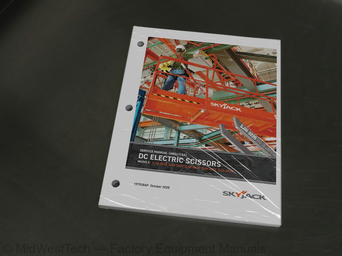
Skyjack SJIII 3220, SJIII 3226, SJIII 4620, SJIII 4626, SJIII 4632 Electric Scissor Lift Service Manual
187 pages · Publication 157928AP
Added to your cart. View cart
- Models
- SJIII 3220, SJIII 3226, SJIII 4620, SJIII 4626, SJIII 4632
- Serial coverage
- As printed on applicability page: SJIII 3220: 60002259 - 60999999
- SJIII 3226: 27006432 - 27999999
- SJIII 4720: 70007139 - 70999999
- SJIII 4726: 70007139 - 70999999
- SJIII 4732: 70007139 - 70999999
- Manual type
- Service Manual
- Pages
- 187
- Publication
- 157928AP
- Condition
- Brand new
What's inside
From the manual's own table of contents: 6 sections, 235 entries. See sample pages (PDF, 514 KB)
Section 1 - scheduled maintenance24 topics
- Aerial Platform and Mobile Elevating Work Platform Definition
- Purpose of Equipment
- Use of Equipment
- Manuals
- Service Policy and Warranty
- Operator Safety Reminders, Warnings and Precautions
- Operator’s Responsibility for Maintenance
- Maintenance and Inspection Schedule
- Owner’s Annual Inspection Record
- Replacement Parts
- Maintenance and Service Safety Tips
- Hydraulic System & Component Maintenance and Repair
- Maintenance Hints
- Railing Maintenance and Repair
- Service and Maintenance
- About this Section
- Service Bulletins
- Maintenance and Inspection
- Maintenance Instructions
- Table 1.1 Owner’s Annual Inspection Record
- Table 1.2 Pre-Delivery/Maintenance Inspection Checklist
- Scheduled Maintenance
- Scheduled Maintenance Inspections
- Function Tests
Section 2 - maintenance tables and diagrams8 topics
- Table 2.1 Specifications and Features
- Table 2.1 Specifications and Features (Continued)
- Table 2.2 Floor Loading Pressure
- Table 2.3 Maximum Platform Capacities (Evenly Distributed)
- Table 2.4 Torque Specifications
- Table 2.5 Torque Specifications for Fasteners (Imperial)
- Table 2.6 Torque Specifications for Fasteners (Metric)
- Table 2.7 Torque Specifications for Hydraulic Couplings & Hoses
Section 3 - System component idenTification and schematics59 topics
- Electrical Symbol Chart
- Charts
- Hydraulic Symbol Chart
- Wire Number and Color Code
- AC Cord Color Code
- Parts List
- Hydraulic Schematic Parts List
- Hydraulic Schematic Parts List (Continued)
- Electrical Components Parts List
- 3.6a Electrical Component Parts List (Continued)
- 3.6b Electrical Component Parts List (Continued)
- 3.7a Hydraulic Manifold and Port Identifications
- 3.7b Hydraulic Manifold and Port Identifications
- Diagrams and Schematics
- 3.8a Platform Control Console Diagram
- 3.8b Platform Control Console Diagram - Long Cable Option
- 3.9a Powerdeck Platform Modification Diagram
- 3.9b Powerdeck Platform Modification Diagram
- 3.10a Powered Extension Platform Control Console and Harness
- 3.10b Powered Extension Platform Control Console
- 3.11a Base Control Console Diagram (Including EE-Rated)
- 3.11b Base Control Console Diagram (Non EE-Rated Only)
- 3.12a Scissor Arm Control Cable Diagram
- 3.12b Scissor Arm Control Cable Diagram (EE-Rated)
- Limit Switch Assembly Wire Diagrams
- Harness Wire Diagrams
- Telematics Harness - ZTR
- 3.16a Hydraulic Schematic (Models 322x)
- 3.16b Hydraulic Schematic (Models 322x)
- 3.17a Hydraulic Schematic (Models 46xx)
- 3.17b Hydraulic Schematic (Models 46xx)
- 3.17c Hydraulic Schematic (Models 46xx)
- Main Manifold Harness
- Main Manifold Harness (EE-Rated)
- Elevate Telematics Harness
- 3.21a Electrical Panel Diagram
- 3.21b Electrical Panel Diagram
- 3.22a Electrical Panel Diagram with Power Deck
- 3.22b Electrical Panel Diagram with Power Deck
- 3.23a Electrical Panel Diagram (EE Rated)
- 3.23b Electrical Panel Diagram (EE Rated)
- 3.23c Electrical Panel Diagram (EE Rated)
- 3.24a Electrical Panel Diagram (EE Rated) with Power Deck
- 3.24b Electrical Panel Diagram (EE Rated) with Power Deck
- 3.24c Electrical Panel Diagram (EE Rated) with Power Deck
- 3.25a Electrical Panel Diagram - Inverter
- 3.25b Electrical Panel Diagram - Inverter
- 3.26a Electrical Panel Diagram with Power Deck - Inverter
- 3.26b Electrical Panel Diagram with Power Deck - Inverter
- Horn/Tilt Switch/Flashing Light Diagram
- 3.28a Electrical Schematic (ANSI/CSA except EE rated - Equipped with no options)
- 3.28b Electrical Schematic (ANSI/CSA except EE rated - Equipped with no options)
- 3.29a Electrical Schematic (EE Rated - Equipped with no options)
- 3.29b Electrical Schematic (EE Rated - Equipped with no options)
- 3.29c Electrical Schematic (EE Rated - Equipped with no options)
- 3.30a Electrical Schematic (All Models - Equipped with all options)
- 3.30b Electrical Schematic (All Models - Equipped with all options)
- 3.30c Electrical Schematic (All Models - Equipped with all options)
- 3.30d Electrical Schematic (All Models - Equipped with all options) - EE-Rated
Section 4 - Troubleshooting Information45 topics
- Introduction
- Electrical System
- 4.1-1 All Controls Inoperative
- 4.1-2 All Controls Except for Down Function Inoperative
- 4.1-3 All Controls Inoperative From Base Control Console
- 4.1-4 All Controls Inoperative From Platform Control Console
- 4.1-5 No Drive or Up Function from Platform or Base Controls (CE only)
- 4.1-6 No Down or Reverse Only Function from Platform Controls
- 4.1-7 No Up or Forward Only Function from Platform Control Console
- 4.1-8 No Up Function from Platform or Base Control Console
- 4.1-9 No Down Function from Platform or Base Control Console (ANSI/CSA)
- 4.1-10 No Down Function from Platform or Base Control Console (CE)
- 4.1-11 No Up Function from Base Control Console
- 4.1-12 No Down Function from Base Control Console
- 4.1-13 Steer Only Inoperative
- 4.1-14 Drive Only Inoperative
- 4.1-15 No Drive or Steer when Platform Fully Lowered
- 4.1-16 No Drive or Steer when Platform Elevated
- 4.1-17 Elevated Drive Speed Does not Activate
- 4.1-18 Work Platform Drives in Slow Speed Only
- 4.1-19 Forward Drive Function Inoperative
- 4.1-20 Reverse Drive Function Inoperative
- 4.1-21 Brake will not Release
- 4.1-22 High/Low Torque Inoperative
- 4.1-23 Right Steer Inoperative
- 4.1-24 Left Steer Inoperative
- 4.1-25 Power Extension Platform will not Extend or Retract
- 4.1-26 Power Extension Platform will not Extend
- 4.1-27 Power Extension Platform will not Retract
- 4.1-28 Two or more Functions at one time
- Hydraulic Systems
- 4.2-1 All Function Inoperative
- 4.2-2 Platform Drifts Down
- 4.2-3 Platform Lifts Slowly
- 4.2-4 Platform does not Lift
- 4.2-5 Platform will not Lower
- 4.2-6 Platform Drives Slow
- 4.2-7 Platform will not Drive in Forward or Reverse
- 4.2-8 Brake(s) will not Release
- 4.2-9 Brake(s) will not Release (Additional for machines with Integral Brakes)
- 4.2-10 Aerial Platform will not hold on a Grade (Machines with Integrals Brakes)
- 4.2-11 Platform does not Steer
- 4.2-12 All System sluggish
- 4.2-13 Power Extension Platform will not Extend or Retract
- 4.2-14 High/Low Torque Inoperative
Section 5 - Procedures20 topics
- Service & Maintenance
- General
- Safety and Workmanship
- Platform
- 5.1-1 OEM Controller Electronics Information
- 5.1-2 OEM Controller Troubleshooting
- 5.1-3 OEM Controller Switch Wiring
- 5.1-4 Gate Spring Hinge Adjustment
- 5.1-5 Railing Modification to Enhance Resistance to Damage
- 5.1-6 Platform Mounting Hardware
- Base
- 5.2-1 System Relief Pressure Adjustment
- 5.2-2 Lift Pressure Adjustment
- 5.2-3 Electronic Tilt Switch Setup Procedure
- 5.2-4 Pothole Limit Switches (LS4 & LS5) Replacement and Adjustment
- 5.2-5 Wheel Replacement and Torquing Procedure
- 5.2-6 Tightening and Torque Recommendations for Hydraulic Couplings and Hoses
- 5.2-7 Battery Maintenance
- 5.2-8 Charger Maintenance - Delta-Q
- 5.3-1 High Speed Cutout Limit Switches (LS1A & LS1B) & Drive Override Limit Switch (LS6) Replacement and Adjustment
Section 6 - APPENDIX A73 topics
- Electrical Component Parts List
- Platform Control Console Diagram
- Scissor Assembly Limit Switches
- 6.4a Electrical Panel Diagram - Motor Controller
- 6.4b Electrical Panel Diagram - Motor Controller
- 6.4c Electrical Panel Diagram - Motor Controller
- 6.5a Electrical Panel Diagram Powerdeck - Motor Controller
- 6.5b Electrical Panel Diagram Powerdeck - Motor Controller
- 6.5c Electrical Panel Diagram Powerdeck - Motor Controller
- 6.6a Electrical Panel Diagram - Motor Controller - Inverter Option
- 6.6b Electrical Panel Diagram - Motor Controller - Inverter Option
- 6.6c Electrical Panel Diagram - Motor Controller - Inverter Option
- 6.7a Electrical Panel Diagram Powerdeck - Motor Controller - Inverter Option
- 6.7b Electrical Panel Diagram Powerdeck - Motor Controller - Inverter Option
- 6.7c Electrical Panel Diagram Powerdeck - Motor Controller - Inverter Option
- Main Manifold Harness - Motor Controller
- Hydraulic Schematic (Models 32XX) - Motor Controller
- 6.10a Hydraulic Schematic (Models 46XX) - Motor Controller
- 6.10b Hydraulic Schematic (Models 46XX) - Motor Controller
- 6.11a Electrical Schematic - Motor Controller
- 6.11b Electrical Schematic - Motor Controller
- 6.11c Electrical Schematic - Motor Controller
- Troubleshooting
- Introduction - Troubleshooting
- 6.12-1 All Controls Inoperative
- 6.12-2 All Controls Except for Down Function Inoperative
- 6.12-3 All Controls Inoperative From Base Control Console
- 6.12-4 No Up Function from Base Control Console
- 6.12-5 Up Function Slow from Base Control Console
- 6.12-6 No Down Function from Base Control Console
- 6.12-7 All Controls Inoperative From Platform Control Console
- 6.12-8 No Up Function from Platform Controls
- 6.12-9 Up Function Slow from Platform Control Console
- 6.12-10 No Down Function from Platform Controls
- 6.12-11 Steer Only Inoperative
- 6.12-12 Right Steer Inoperative (Without power deck option)
- 6.12-13 Right Steer Inoperative (With power deck option)
- 6.12-14 Left Steer Inoperative (Without power deck option)
- 6.12-15 Left Steer Inoperative (With power deck option)
- 6.12-16 Drive Only Inoperative
- 6.12-17 No Drive or Steer when Platform Fully Lowered
- 6.12-18 No Drive or Steer when Platform Elevated
- 6.12-19 Platform Drives in Slow Speed Only
- 6.12-20 High/Low Torque Inoperative
- 6.12-21 Brake will not Release
- 6.12-22 Forward Drive Function Inoperative
- 6.12-23 Reverse Drive Function Inoperative
- 6.12-24 Power Extension Platform will not Extend or Retract
- 6.12-25 Power Extension Platform will not Extend
- 6.12-26 Power Extension Platform will not Retract
- 6.13-1 All Function Inoperative
- 6.13-2 All System sluggish
- 6.13-3 Platform Drifts Down
- 6.13-4 Platform Lifts Slowly
- Hydraulic System
- 6.13-5 Platform does not Lift
- 6.13-6 Platform will not Lower
- 6.13-7 Platform Drives Slow
- 6.13-8 Platform will not Drive in Forward or Reverse
- 6.13-9 Brake(s) will not Release (Pin brakes)
- 6.13-10 Brake(s) will not Release (Integral brakes)
- 6.13-11 Aerial Platform will not hold on a Grade (Integral brakes)
- 6.13-12 Platform does not Steer
- 6.13-13 Power Extension Platform will not Extend or Retract
- 6.13-14 High/Low Torque Inoperative
- Procedure
- General
- Safety and Workmanship
- 6.14-1 OEM Controller Electronics Information
- 6.14-2 OEM Controller Troubleshooting
- 6.14-3 OEM Controller Switch Wiring
- 6.14-4 Gate Spring Hinge Adjustment
- 6.15-3 Resistor - Voltage Divider
Inside this manual
Real pages from this service manual (187 pages). Open the sample pages (PDF, 513 KB)

- Specifications, page 30: Section 2 - Maintenance Tables and Diagrams
- Diagram, page 62: Section 3 - System Component Identification and Schematics
- Troubleshooting, page 166: Section 6
- Color page, page 37: SJIII DC Electric
- Color page, page 141: SJIII DC Electric
- Foldout diagram (color), page 78: SJIII DC Electric
Other manuals for this machine
Save 10% on 2 manuals, 15% on 3 or more. Other manuals are listed below. Editions cover different serial number ranges: check the serial coverage and tick only the ones that match your machine.
Added to your cart. View cart
This is a service manual
Here's how it compares to the other manual types.
Service manual
Factory repair procedures and technical information such as specifications, troubleshooting, and wiring and hydraulic diagrams, for the models and systems the manual covers. See What's inside for its topics.
Operator's manual
Safe operation, controls, maintenance schedules, lubrication points, inspections, and basic checks. Repair procedures are in the service manual.
Parts manual
Illustrated diagrams with factory part numbers for identifying components and ordering parts. Repair procedures are in the service manual.
Engine service manuals are sometimes sold separately, since certain machine models were offered with more than one engine option.
What it's used for
Factory manual for in-house farm and construction shop use. Straightforward, complete, and easy to follow. It contains the OEM information dealership service departments and parts counters use to diagnose problems, identify components, and perform maintenance or repairs correctly.
Service shops and owner/operators who repair their own equipment
Identifying correct parts and seeing how assemblies come apart and go back together
Keeping equipment running with less downtime
Factory manual, 187 pages
Quantity one is the manual described above.
Fast free USA shipping
Ships in 1 business day.
60-day returns
Free if the mistake is ours. A manual ordered in error must come back unopened in its shrink-wrap; you pay return shipping and a 20% restocking fee applies. Return policy
Other editions and similar models
Questions about model, serial number, engine coverage or contents? Contact us before purchasing and we'll help confirm it's the right manual. Please verify the manual type, machine model, serial number range and engine coverage before purchasing: manuals ordered in error carry a 20% restocking fee (return policy).