Specifications
Description
Chassis
Operator's Console
Operator Compartment Options
Steering and Controls
Steer Controller Guidance System
DriveandBrake
Driveunit
Brake
Mast Assembly
HydraulicComponents
Lift/Lower System
Electrical Components and Systems
General
Miscellaneous Circuits
Fuses
Sidegate Switches (S60. S6 1)
Tie - Points
Cables
Planned Maintenance
PlannedMaintenance
General Maintenance Instructions
Introduction
Maintenance Manual
BatteryMaintenance
BatterySafety
Battery Inspection and Care
Battery Cleaning Procedure
Charging Process
Troubleshooting
How to Use This Chapter
Electrical Troubleshooting Guidelines
Electrical Connector Locator Chart
Shorts to Frame Test
Electric Motor Tests
MotorTypes
Open Circuit Motor Test
Grounded Motor Test
Short Circuited Armature or Field Winding
Hydraulic Troubleshooting Guidelines
HydraulicLeakage
List of Troubleshooting Charts
Electrical Codes and Tests
Modes of Operation
Overview
Passwords
Disable the Brush Wear Warning
Entering the Secondary Password
Start the Hour Meter
Entering the Secondary Password
Self - diagnosis Mode
Self-diagnosis Mode
Analyzer (AnL) Mode
Entering Analyzer Mode
Maneuvering within Analyzer Mode
Tuning (Tuning) Mode
Entering the Secondary Password
Maneuvering within Tuning Mode
Exiting Tuning Mode
Calibrate (Calibrte) Mode
Entering Calibrate Mode
Maneuvering within Calibrate Mode
Configure (Configur) Mode
Code Summary Tables
Analog Inputs
Category 1 Class 2
Tests
CodesandTests
Analog Input Tests: (Category 1. Class 2: 12)
12 - 20: Steer Controller Power Supply Voltage
Component Locator Photos
Maintenance Practices
Adjustment and Repair
Powersection
Electrical Functions
Operating Description Overview
LiftILower System
Lift
Lower
Brakingsystem
Appendix
Lubrication Equivalency Chart
Torque Chart Standard (Ferrous)
Torque Chart Standard (Brass)
Torque Chart . Metric
Decimal Equivalent Chart
StandardIMetric Conversions
Electrical Schematic
Hydraulic Schematic
Index
Figure 2 - 1 : Anti - Static Kit with Wrist Strap and Mat
Figure 2 - 2: Correct Jacking Locations
Figure 3 - 1 : Toyota Orderpicker
Figure 3 - 2: Component Identification
Figure 3 - 3: Operator's Console
Figure 3 - 4: Hydraulic Compartment Components (Sheet 1 of 2)
Figure 3 - 5: Electrical Compartment Components
Figure 3 - 7: Caniage Interface Card
Figure 3 - 8: Tractor Interface Card
Figure 3 - 9: Steer Controller Card
Figure 3 - 10: Display Controller Card
Figure 3 - 1 1 : Filter Card (with wire guidance only)
Figure 4 - 1: Lubrication/Inspection Points
Figure 5 - 1 : Shorts to Frame Test
Figure 5 - 2: Motor Circuits
Figure 5 - 3: GEN 1 : General Troubleshooting
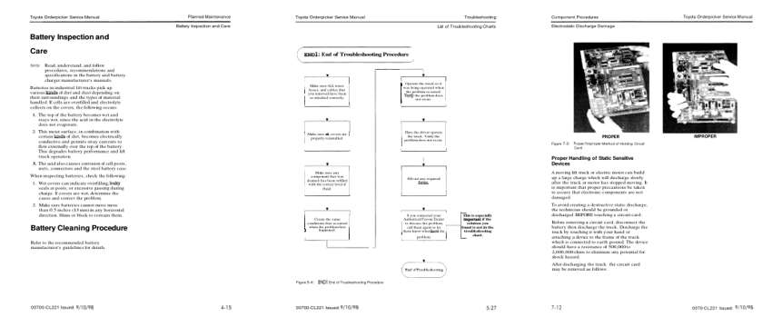
Figure 5 - 4: END 1 : End of Troubleshooting Procedure
Figure 5 - 5: W - 1 : Truck Functions Partially
Figure 5 - 6: H - 1 : Hydraulic Lift/Lower Problem
Figure 5 - 7: H - 2: No Lift; Lift Motor/Pump Won't Turn
Figure 5 - 8: H - 3: No Lift; Lift Pump/Motor Rotate
Figure 5 - 9: H - 4: Load Drifts Down while Forks are Elevated
Figure 5 - 10: H - 5: Cannot Pick Up a Load
Figure 5 - 12: T - 2: No Travel in Either Direction
Figure 5 - 13: T - 3: Travel in One Direction Only
Figure 5 - 14: T - 4: Problem with Slow Travel
Figure 5 - 15: T - 5: Truck Does Not Accelerate Properly
Figure 5 - 16: T - 6: Truck Does Not Travel1 topic
Figure 5 - 18: T - 8: Slow travel Speed Occurs All the Time
Figure 6 - 1 : Menu Structure for the Different Modes
Figure 6 - 2: Steer Controller Card . Code 52
Figure 6 - 3: Steer Controller Card . Code 53
Figure 6 - 4: Location of Wire Guidance Coils and Related Tests
Figure 6 - 5: Location of Wire Guidance Coils and Related Tests
Figure 6 - 6: Location of Wire Guidance Coils and Related Tests
Figure 6 - 7: Location of Wire Guidance Coils and Related Tests
Figure 6 - 8: Location of Wire Guidance Coils and Related Tests
Figure 6 - 9: Location of Wire Guidance Coils and Related Tests
Figure 7 - 1 : Component Locations (Sheet 1 of 5)
Figure 7 - 2: Correct Jacking Locations
Figure 7-3: Proper/Improper Method of Holding Circuit Card
Figure 7-4: Integrated Circuit Tool
Figure 7-5: Preparing Integrated Circuit for Insertion
Figure 7-6: Installation of Integrated Circuit
Figure 7-7: Removing Drive Unit
Figure 7-8: Drive Unit Senice Tools
Figure 7-9: Drive Unit Cross Section
Figure 7- 12: Pressing Bearing Cone onto Axle
Figure 7 - 13: Assembly of Axle into Housing
Figure 7- 14: Preparing Axle Seal for Assembly into Housing
Figure 7 - 15: Install/Torque Clamp Nut on Axle
Figure 7 - 16: Securing Clamp Nut by Tightening Retaining Screw
Figure 7 - 17: Installing Cover
Figure 7- 18: Drive Unit Assembly
Figure 7 - 19: Checking Skidpads
Figure 7 - 20: Deadman Pedal/Master Cylinder
Figure 7 - 2 1: Brake Bleeding Set-Up
Figure 7 - 22: Exploded View of Brake Assembly
Figure 7-23: Deadman Switch (S2) Adjustment (Not to Scale)
Figure 7-24: 2 Stage Lift Cylinder (Top End)
Figure 7-25: 2 Stage Lift Cylinder (Bottom End)
Figure 7-26: Center Lift Cylinder, 3 Stage (Top End)
Figure 7-27: Center Lift Cylinder, 3 Stage (Bottom End)
Figure 7 - 28: Lift/Lower Manifolds
Figure 7-29: Proper Installation of Proportional Valve
Figure 7 - 30: Access for Lift Cylinder Bleed Screws
Figure 7 - 31: Directional/Speed Control . Exploded View
Figure 7-32: Lift/Lower Return Spring Replacement
Figure 7-33: Lift/Lower Control Assembly, Potentiometer Wiring
Figure 7 - 34: Elevating Section
Figure 7 - 35: Elevating Section (cont.)
Figure 7 - 36: Elevating Section (cont.)
Figure 7 - 37: Elevating Section (cont.)
Figure 7-38: Three Stage Elevating Section
Figure 7-39: End Cap Pulley Assembly (3 Stage mast only)
Figure 7 - 40: Staging of Mast Prior to Shimming Bearings
Figure 7 - 4 1 : End Cap Assembly, 3 Stage Mast
Figure 7 - 42: Steering Control Assembly
Figure 8 - 1: Steering Encoder Output . Left Turn
Figure 8 - 2: Steering Encoder Output . Right Turn
Figure 8 - 3: Wire Guidance Functional Block Diagram
Figure 8 - 4: Location of Wire Guidance Coils and Related Tests
Figure 8 - 5: Wire Guidance LEDs on the Operator's Display
Figure 9 - 1 : Lubrication Equivalency Chart
Figure 9 - 2: Torque Chart . Standard
Figure 9 - 3: Torque Chart . Standard Brass
Figure 9 - 4: Torque Chart . Ferrous Metric
Figure 9 - 5: Torque Chart . Brass Metric
Figure 9 - 6: Decimal Equivalent Chart
Figure 9 - 7: Electrical Schematic
Figure 9 - 8: Electrical Schematic
Figure 9 - 9: Hydraulic Schematic