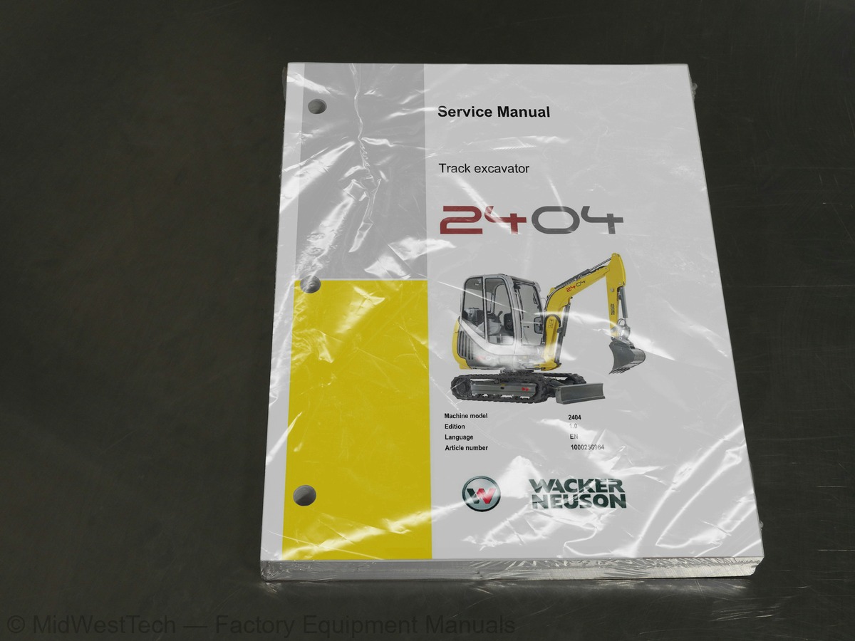
Wacker Neuson 2404 Track Excavator Service Manual
238 pages · Publication 1000256964
Added to your cart. View cart
- Models
- 2404
- Manual type
- Service Manual
- Pages
- 238
- Publication
- 1000256964
- Condition
- Brand new
What's inside
From the manual's own table of contents: 59 sections, 273 entries. See sample pages (PDF, 773 KB)
General52 topics
- Important information on this service manual
- Identification of warnings and dangers
- Designated use and exemption from liability
- Type labels and component numbers
- Machine overview
- Cab overview
- Cab (legend)
- Instrument panel overview
- Instrument panel legend
- Engine compartment overview
- Overview of the engine compartment rear side
- Chassis overview
- Overview of right/left-hand side chassis
- Engine
- Fuel injection pump
- Engine capacities
- Engine tightening torques
- Hydraulic system
- Auxiliary hydraulics oil flow
- Undercarriage and swivel unit
- Stabiliser blade
- Screwable hose burst valve
- Electrical system
- Noise levels
- Vibration
- Coolant compound table
- Towing and raising
- Model-specific tightening torques
- General tightening torques
- Tightening torques for hydraulic screw connections (dry assembly)
- Tightening torques for high-resistance screw connections
- Dimensions 2404
- Dimensions 2404 VDS (option)
- Lift capacity table 2404
- Short stick
- Long stick
- Lift capacity table 2404 VDS
- Kinematics
- Attachments
- Fluids and lubricants
- Additional oil change and filter replacement (hydraulics)
- Maintenance plan (overview)
- Introduction
- Fuel system
- Specific safety instructions
- Refuelling
- Stationary fuel pumps
- Diesel fuel specification
- Bleeding the fuel system
- Emptying the fuel tank
- Fuel prefilter with water separator
- Replacing the fuel filter
Engine lubrication system4 topics
- Checking the oil level
- Filling up engine oil
- Changing engine oil
- Replacing the engine oil filter cartridge
Cooling system3 topics
- Checking/filling up coolant
- Filling up coolant
- Draining coolant
Air filter3 topics
- Replacing the filter elements
- Daily inspection of the fouling indicator
- Functional check once a week of the dust valve
V-belt2 topics
- Checking V-belt tension
- Retightening the V-belt
Hydraulic system7 topics
- Checking the hydraulic oil level
- Filling up hydraulic oil
- Changing hydraulic oil
- Replacing the hydraulic oil filter
- Draining condensation water from the hydraulic oil tank
- Bleeding the hydraulic pump
- Checking hydraulic pressure lines
Pressure check9 topics
- General
- Checking pilot control pressure
- Pressure check of variable displacement pump P1
- Pressure check of variable displacement pump P2
- Pressure check of gear pump P3
- Secondary pressure limiting valve for swivel unit
- Secondary pressure limiting valve of travelling drive
- Measuring ports: overview
- Overview of primary pressure limiting valves
Power train2 topics
- Checking the oil level and filling up oil
- Draining oil
Tracks2 topics
- Checking track tension
- Setting the tracks
Lubrication work60 topics
- Swivelling console
- Boom ram
- Stick ram
- Bucket ram
- Bucket joint
- Lubrication strip
- VDS (option)
- Mechanical quickhitch (option)
- Hydraulic quickhitch (option)
- Maintenance of attachments
- Service and maintenance work at regular intervals
- Instructions concerning specific components
- Alternator
- Battery
- Cab and seat console
- Removing the cab
- Raising the seat console with the cab
- General maintenance work
- Cleaning
- General instructions for all areas of the machine
- Inside the cab
- Exterior of the machine
- Engine compartment
- Screw connections and attachments
- Engine 3TNV76-SNS
- Checking and adjusting valve clearance
- Tightening order for cylinder head bolts
- Checking the injection nozzles
- Injection nozzle design
- Pressure check
- Leakage check
- Checking the nozzle jet
- Injection time
- Checking injection time
- Setting injection time
- Mounting and removing the injection pump
- Removing the injection pump
- Fitting the injection pump
- Measuring and adjusting the engine speed
- Checking compression
- Checking the coolant thermostat
- Checking the temperature switch
- Oil pressure switch
- Checking the coolant circuit
- Cleaning the cooling water channels
- Coolant and fuel hoses
- Crankcase vent
- Replacing the glow plugs
- Hydraulic pump PVD-0B-22BP
- Pump unit exploded view
- Pilot oil supply unit
- Dismantling the hydraulic pump
- Assembling the hydraulic pump
- Troubleshooting on the hydraulic pump
- Main valve block
- Sections and ports
- Legend
- Main valve block diagram
- Pressure limiting and other valves
- Pump assignment
Drive counterbalancing system1 topic
- Pump assignment for drive counterbalancing
Pilot valves3 topics
- Joystick on left and right
- Pilot valve (driving)
- Auxiliary hydraulics pedal
Valves2 topics
- 7/2 directional valve (changeover valve)
- 8/2 directional valve – changeover valve SAE/ISO controls (option)
Travelling drive1 topic
- Function
Swivel unit1 topic
- Swivel unit design
Show all 60 sections
Swivel joint1 topic
- Sealing the swivel joint
Relays1 topic
- Use, mode of function
Relay box with main fuse1 topic
- Relay connector assignment
Control lever tip switch34 topics
- Standard control lever
- Control lever (option)
- A alternator and dynamo
- Regulator
- Starter
- Working lights (option)
- Rotating beacon (option)
- Driving signal (option)
- Wiring diagram A4 (legend)
- Wiring diagram A4
- Wiring diagram legend with 40 A alternator A4 (option)
- Wiring diagram with 40 A alternator A4 (option)
- Wiring diagram A3 (legend)
- Wiring diagram A3
- Wiring diagram legend with 40 A alternator A3 (option)
- Wiring diagram with 40 A alternator A3 (option)
- Flat seal couplings
- Installing a grab
- 3rd control circuit/PowerTilt connection
- Auxiliary hydraulics connections
- Safe load indicator DE up to serial number AF05561
- Wiring diagram
- Setting the pressure switch
- Safe load indicator DE from serial number AF05562
- Safe load indicator FR up to serial number AF05561
- Safe load indicator FR from serial number AF05562
- stick and stabiliser blade)
- Vertical digging system (VDS)
- KAT drive interlock (antitheft protection)
- Malfunctions
- Drive interlock (antitheft protection) Trebe
- Disabling the drive interlock
- Enabling the drive interlock
- Programming
Proportional controls7 topics
- Auxiliary hydraulics control/3rd control circuit control
- Programming characteristic curves
- Solenoid valve connections
- Control unit connector assignment
- Safety features
- Measures to be taken in case of malfunctions
- Diagnosis display
General instructions5 topics
- General safety instructions
- Checking the product
- Decompression valve
- Testing the hydraulic system of the machine
- Specifications/requirements
Tools1 topic
- Making a tool VI for removing the seals
Replacement sealing kit A and bearing kit B10 topics
- Dismantling the base blocks
- Removing the end cap
- Removing the shaft
- Removing the piston tube body
- Removing all seals (kit A), shaft bearing and pressure discs (kit B)
- Fitting seals (kit A), shaft bearing and pressure discs (kit B)
- Fitting the piston tube body
- Fitting the shaft
- Mounting the end cap
- Fitting the base blocks
Lubrication and tests2 topics
- Lubrication
- Test
Inside this manual
Real pages from this service manual (238 pages). Open the sample pages (PDF, 771 KB)

- Specifications, page 48: SERV-HB 2404 EN – Edition 1.0 *2404s310.fm
- Diagram, page 171: SERV-HB 2404 EN – Edition 1.0 *2404s611.fm
- Troubleshooting, page 213: SERV-HB 2404 EN – Edition 1.0 *2404s710.fm
- Color page, page 120: SERV-HB 2404 EN – Edition 1.0 *2404s510.fm
- Color page, page 21: SERV-HB 2404 EN – Edition 1.0 *2404s110.fm
- Foldout diagram (color), page 179: Electrical system
Other manuals for this machine
Save 10% on 2 manuals, 15% on 3 or more. Other manuals for the 2404 are listed below. Editions cover different serial number ranges: check the serial coverage and tick only the ones that match your machine.
Added to your cart. View cart
This is a service manual
Here's how it compares to the other manual types.
Service manual
Factory repair procedures and technical information such as specifications, troubleshooting, and wiring and hydraulic diagrams, for the models and systems the manual covers. See What's inside for its topics.
Operator's manual
Safe operation, controls, maintenance schedules, lubrication points, inspections, and basic checks. Repair procedures are in the service manual.
Parts manual
Illustrated diagrams with factory part numbers for identifying components and ordering parts. Repair procedures are in the service manual.
Engine service manuals are sometimes sold separately, since certain machine models were offered with more than one engine option.
What it's used for
Factory manual for in-house farm and construction shop use. Straightforward, complete, and easy to follow. It contains the OEM information dealership service departments and parts counters use to diagnose problems, identify components, and perform maintenance or repairs correctly.
Service shops and owner/operators who repair their own equipment
Identifying correct parts and seeing how assemblies come apart and go back together
Keeping equipment running with less downtime
Factory manual, 238 pages
Quantity one is the manual described above.
Fast free USA shipping
Ships in 1 business day.
60-day returns
Free if the mistake is ours. A manual ordered in error must come back unopened in its shrink-wrap; you pay return shipping and a 20% restocking fee applies. Return policy
Questions about model, serial number, engine coverage or contents? Contact us before purchasing and we'll help confirm it's the right manual. Please verify the manual type, machine model, serial number range and engine coverage before purchasing: manuals ordered in error carry a 20% restocking fee (return policy).