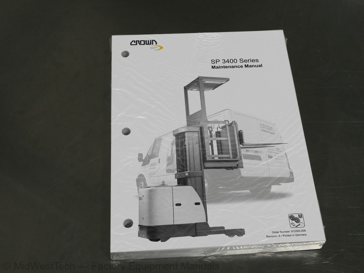
Crown SP 3400 Series High Level Order Picker Service Manual
446 pages · Publication 812563-006
Added to your cart. View cart
- Models
- SP 3400 Series
- Manual type
- Service Manual
- Pages
- 446
- Publication
- 812563-006
- Condition
- Brand new
What's inside
From the manual's own table of contents: 508 topics. See sample pages (PDF, 567 KB)
- Symbols Used in the Manual
- Safety Symbols
- General Symbols
- Fork direction
- General Safety Instructions
- Maintenance and Repair Instructions
- Maintenance and Repair
- Before Parking the Truck
- Before Working on the Truck
- Before Starting the Truck
- Warning and Instruction Decals on the Truck
- Control of Hazardous Energy
- Battery
- Safety Rules
- Battery Removal
- Battery Installation
- Lockout - Tagout
- Brake
- Capacitance
- Hydraulic System
- Depressurising the hydraulic system
- Accumulator
- Lifting and Blocking
- Required tools
Show all 508 topics
- Raising the Side
- Raising the Drive Wheel
- Blocking Masts
- Cleaning Methods
- General
- Operating Instructions
- Service Training
- Ordering Spare Parts
- Using the Manual
- Data Plate
- Model Number
- Truck Data Number
- Charts
- Componentry
- Status Alarm
- Battery Restraint Switch
- Brake Switch
- Chain Slack Switches (TT Mast Only)
- Chain Slack Switches
- Check Valve
- Free Lift (TT Mast Only)
- Mast
- Display Module
- Display Switch
- Drive / Tow Switch
- Steering Command Encoder
- Steering Feedback Encoder
- Traction Speed Encoder
- Lift Height Sensor
- Emergency Disconnect Main Contactor
- Emergency Disconnect Traction & Steering Contactor
- Emergency Disconnect Switch
- Operator Fan
- Return
- Fan Switch
- Forward Switch
- Lights and Fan Fuse
- Control Fuse
- Options Fuse
- Manual Brake Fuse
- Brake Outer Coil Fuse
- Brake Inner Coil Fuse
- Pump Motor 1 Fuse
- Pump Motor 2 Fuse
- Steer Module Fuse
- Freezer Condition Power Unit Fuse
- Freezer Condition Platform Fuse
- Traction Motor Fuse
- Guidance Control Module
- Side Gate Switches
- Rear Gate Switches
- Guidance Switch
- Horn
- Back-Up or Travel Alarm
- Horn Switch
- High Speed Lower Cutout Switch
- High Speed Raise Cutout Switch
- mm (24 in.) Height Limit Switch
- mm (60 in.) Height Limit Switch
- mm (120 in.) Height Limit Switch
- mm (150 in.) Height Limit Switch
- mm (180 in.) Height Limit Switch
- Power Up Relay
- Module Power
- Steer Motor Relay
- Freezer Condition Relay
- Key Switch
- Lower Cutout Switch
- Dome Light Switch
- Work Light Switch
- Spot Light Switch
- Strobe or Flashing Light
- Work Lights
- Dome Lights
- Spot Lights
- Low Speed Lower Switch
- High Speed Lower Switch
- Traction Motor
- Power Steering Motor
- Lift Pump Motor
- Traction Module
- Manual Valve Lowering
- Override Switch
- Low Speed Lift Pump Contactor
- Low Speed Lift Pump
- High Speed Lift Pump Contactor
- High Speed Lift Pump
- Traction Request Potentiometer
- Light Power Supply
- Proportional Lowering Valve
- Low Speed Raise Switch
- High Speed Raise Switch
- Raise Cutout Switches
- Resistor
- Freezer Condition Heater
- Reservoir
- Rail Guide Switches
- Reverse Switch
- Relief Valve
- Suppressor Block
- Steering Control Module
- Wire Guidance
- Suction
- Test Port
- Power Unit Thermostat
- Platform Thermostat
- Zone Select Switch
- Skids
- Torque Values
- Hydraulic Symbols
- Hydraulic Circuits
- Lift Circuit - One Speed Lift
- Relief Valve Operation
- Accumulator Operation
- Lift Circuit - Two Speed Lift
- Low Speed Lift
- High Speed Lift
- Lower Circuit - One Speed/Two Speed Lower
- Lower
- Manual Lower Circuits
- Lifting Fork Lift Circuit
- Lift Circuit - Two Speed Lift W/Lifting Forks
- Hydraulic Lines and Fittings
- Filter
- Drift Test
- Lift Drift Test
- Freezer Preparation
- Hydraulic Pump
- Pump - Gear
- Oil Seal Removal
- Oil Seal Replacement
- Pump Disassembly
- Parts Inspection
- Pump Reassembly
- Lift/Lower Control Valve
- Relief Valve- RV1 Operation
- Adjustment (1.25 Trucks)
- Relief Valve- RV1 & RV2 Operation
- Adjustment (1.0 Trucks)
- Precharging
- Maintenance
- Hydraulics Troubleshooting Chart
- Drive Tire Replacement
- Drive Unit Lubrication
- Encoders
- Electrical Wiring
- Wiring Color Codes
- Color
- Number
- Power Cables
- Symbols
- Basic Symbols
- Motor Monitoring System (MMS)
- Overtemperature Sensors
- Brushwear Sensors
- Event Codes
- Some Troubleshooting Basics
- Check the Event Code Listing
- No Event Code?
- To Locate Malfunctioning Components
- Test Points
- Event Code 201
- Event Code 202
- Event Code 204
- Event Code 208
- Event Code 209
- Event Code 210
- Event Code 211
- Event Code 212
- Event Code 213
- Event Code 215
- Event Code 216
- Event Code 217
- Event Code 218
- Event Code 219
- Event Code 221
- Event Code 222
- Event Code 223
- Event Code 224
- Event Code 227
- Event Code 228
- Event Code 311
- Event Code 312
- Event Code 313
- Event Code 314
- Event Code 315
- Event Code 316
- Event Code 317
- Event Code 318
- Event Code 319
- Event Code 321
- Event Code 322
- Event Code 323
- Event Code 324
- Event Code 326
- Event Code 327
- Event Code 328
- Event Code 331
- Event Code 332
- Event Code 333
- Event Code 334
- Event Code 335
- Event Code 336
- Event Code 337
- Event Code 339
- Event Code 341
- Event Code 342
- Event Code 343
- Event Code 344
- Event Code 345
- Event Code 346
- Event Code 347
- Event Code 348
- Event Code 349
- Event Code 351
- Event Code 352
- Event Code 353
- Event Code 354
- Event Code 355
- Event Code 356
- Event Code 357
- Event Code 358
- Event Code 362
- Event Code 363
- Event Code 364
- Event Code 365
- Event Code 366
- Event Code 367
- Event Code 368
- Event Code 369
- Event Code 371
- Event Code 372
- Event Code 373
- Event Code 374
- Event Code 375
- Event Code 376
- Event Code 377
- Event Code 378
- Event Code 379
- Event Code 381
- Event Code 382
- Event Code 383
- Event Code 384
- Event Code 385
- Event Code 386
- Event Code 387
- Event Code 388
- Event Code 391
- Event Code 392
- Event Code 393
- Event Code 394
- Event Code 396
- Event Code 397
- Event Code 398
- Event Code 399
- Event Code 411
- Event Code 412
- Event Code 413
- Event Code 414
- Event Code 415
- Event Code 416
- Event Code 417
- Event Code 418
- Event Code 419
- Event Code 421
- Event Code 422
- Event Code 423
- Event Code 424
- Event Code 425
- Event Code 426
- Event Code 427
- Event Code 428
- Event Code 429
- Event Code 431
- Event Code 432
- Event Code 433
- Event Code 434
- Event Code 435
- Event Code 436
- Event Code 437
- Event Code 438
- Event Code 439
- Event Code 441
- Event Code 442
- Then replace GCM
- Event Code 800
- Event Code 801
- Event Code 802
- Event Code 803
- Event Code 804
- Event Code 805
- Event Code 806
- Event Code 807
- Event Code 808
- Event Code 809
- Event Code 810
- Event Code 811
- Event Code 812
- Event Code 813
- Event Code 814
- Event Code 827
- Event Code 828
- Event Code 829
- Event Code 831
- Event Code 832
- Event Code 833
- Event Code 834
- Event Code 835
- Event Code 836
- Event Code 837
- Event Code 838
- Tune Up
- Service Terminal
- Description
- Service Terminal Operation
- Keyboard Commands
- Calibration
- Truck Setup Menus
- Lift Cutouts or Zone Menus
- Truck Option Menus
- P.M. Interval Setup Menus
- Hourmeter Reset Menus
- Wire Guidance Calibration Menus
- Traction Setups/Calibration Menus
- Traction Setups/Features Menus
- Features/Travel Alarm Menus
- Traction Setups/Performance Menus
- Traction Setups/Performance Menus (cont'd)
- System Information Menus
- View Enable Config Menus
- Truck Monitors Menus / View Encoder Counts Menu
- View Hardware Outputs Menus
- Traction Analyzer Menus
- Status Analyzer Menus
- Traction Inputs Menus
- View Switches Menu
- Traction Outputs Menus
- Wire Guidance System
- Operation Modes
- Manual
- Automatic
- Sensors
- Troubleshooting
- Guidance Module (GCM)
- Pin assignment
- Line Driver Output
- Sensor Bearing
- Checking Truck Steering System
- Truck Steering System Components
- Contactors
- Inspection
- Contacts
- Coil
- Component Replacement
- Contact Replacement
- Coil Replacement
- Steering Feedback
- Gear Assembly
- Control Module
- Access
- Adjustment
- Acceleration Potentiometer (POT1)s
- Directional Switches (FS & RS)
- FS and RS
- Actuator Arm
- Potentiometer (POT1)
- Cam Torsion Spring, Stop
- Twist Grip
- RAS1, RAS2, LOS1, LOS2, HNS, EDS
- Checking
- Battery Care
- Charging
- Placing battery on charge
- Removing battery from charge
- Battery Stop Adjustment
- Battery Cleaning
- Trouble Shooting
- Motors
- Braking Force
- Brake Force Adjustment
- BRAKE ADJUSTMENT
- Air Gap Adjustment
- Torque Gap Adjustment
- Rotor and Brake Pad Replacement
- Brake Assembly
- System Description
- Steering Direction
- Steering Wheel Direction Indicator
- Steering Wheel Adjustment
- Steering Motor Gearbox
- Lift Chains
- Cleaning
- Wear
- Freedom of Movement of Chain Links
- Chain Tension
- Chain Anchor and Pulleys
- Worn Connection Plates
- Protruding or Turned Chain Pins
- Corrosion
- Chain Lateral Wear
- Uneven Chain Tension
- Misaligned Lift Components
- Lift Chain Lubrication
- Separating Lift Chains
- Tools and Equipment Required
- Separation
- FEM / ISO Forks
- Terms
- Fork Identification
- FEM / ISO Fork Inspection
- Repair
- Inspection Intervals
- Crack Inspection
- Fork Blade Warping
- Fork Tip Straightness Test
- Measuring the Fork Tip Height
- Fork Tine Height Difference
- Fork Stop
- Fork Blade Abrasion Check
- Platform Fork Blades
- Fork Inspection
- Overloading
- Bent or Twisted Forks
- Hanger
- Safety
- For your personal protection
- Rod Seal Assembly
- Large Rod Seal Assembly
- Small Seal Rod Assembly
- Rod Seal Assembly, Sealing Lip First
- Mast, Free Lift and Auxiliary Fork Cylinders
- Disassembly
- Accessing Rod Packing- Mast Cylinder
- Accessing Rod Packing - Free Lift Cylinder
- Accessing Rod Packing- Auxiliary Fork Cylinder
- Rod Packing Replacement
- Mast Cylinder Removal
- Auxiliary Fork Cylinder Removal
- Free Lift Cylinder Removal
- Safety Shield Installation
- Floor Mat Replacement
- Forks
- Fork Replacement
- Removal
- Installation
- Pallet Grab (Option)
- Release Handle Adjustment
- Pedal Adjustment
- Pallet Grab Removal
- Operator Compartment Gates
- Spring Replacement
- Operator Egress System
- Platform Removal & Shimming
- Basics
- Platform Removal and Shimming, TL Mast
- Shimming
- Removing the Platform for Shimming
- Platform Removal & Shimming TT Mast
- Block Diagram
- Schematic, Standard
- Schematic with Options
- Platform, Standard
- Platform, Auxiliary Fork Lift
- Distribution Panel
- Traction, Standard
- Traction, Auxiliary Fork Lift
- Display Module (DCM)
- Traction Module (MRC1)
- Steering Module (SCM)
- Traction Control
- Guidance Control Module (GCM)
- Lights, Fan, Power Supply
- Freezer Condition
- Order Information
- Wire Harness
- Platform
- Power Unit
- Platform with Auxiliary Lift Fork
- Single Speed Lift
- Two Speed Lift
- Single Speed Lift With Lifting Forks
- Two Speed Lift With Lifting Forks
- TL Mast
- TT Mast
Inside this manual
Real pages from this service manual (446 pages). Open the sample pages (PDF, 566 KB)
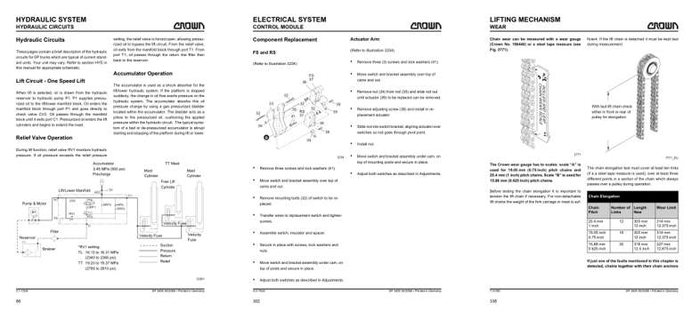
- Diagram, page 104: HYDRAULIC SYSTEM
- Repair procedure, page 320: CONTROL MODULE
- Specifications, page 356: LIFTING MECHANISM
Other manuals for this machine
Save 10% on 2 manuals, 15% on 3 or more. Other manuals for the SP 3400 Series are listed below. Editions cover different serial number ranges: check the serial coverage and tick only the ones that match your machine.
Added to your cart. View cart
This is a service manual
Here's how it compares to the other manual types.
Service manual
Factory repair procedures and technical information such as specifications, troubleshooting, and wiring and hydraulic diagrams, for the models and systems the manual covers. See What's inside for its topics.
Operator's manual
Safe operation, controls, maintenance schedules, lubrication points, inspections, and basic checks. Repair procedures are in the service manual.
Parts manual
Illustrated diagrams with factory part numbers for identifying components and ordering parts. Repair procedures are in the service manual.
Engine service manuals are sometimes sold separately, since certain machine models were offered with more than one engine option.
What it's used for
Factory manual for in-house farm and construction shop use. Straightforward, complete, and easy to follow. It contains the OEM information dealership service departments and parts counters use to diagnose problems, identify components, and perform maintenance or repairs correctly.
Service shops and owner/operators who repair their own equipment
Identifying correct parts and seeing how assemblies come apart and go back together
Keeping equipment running with less downtime
Factory manual, 446 pages
Quantity one is the manual described above.
Fast free USA shipping
Ships in 1 business day.
60-day returns
Free if the mistake is ours. A manual ordered in error must come back unopened in its shrink-wrap; you pay return shipping and a 20% restocking fee applies. Return policy
Binder not included
Manuals over about 300 pages may need a standard 3-ring binder, which you can buy locally to keep the pages organized for shop use.
Other editions and similar models
Questions about model, serial number, engine coverage or contents? Contact us before purchasing and we'll help confirm it's the right manual. Please verify the manual type, machine model, serial number range and engine coverage before purchasing: manuals ordered in error carry a 20% restocking fee (return policy).