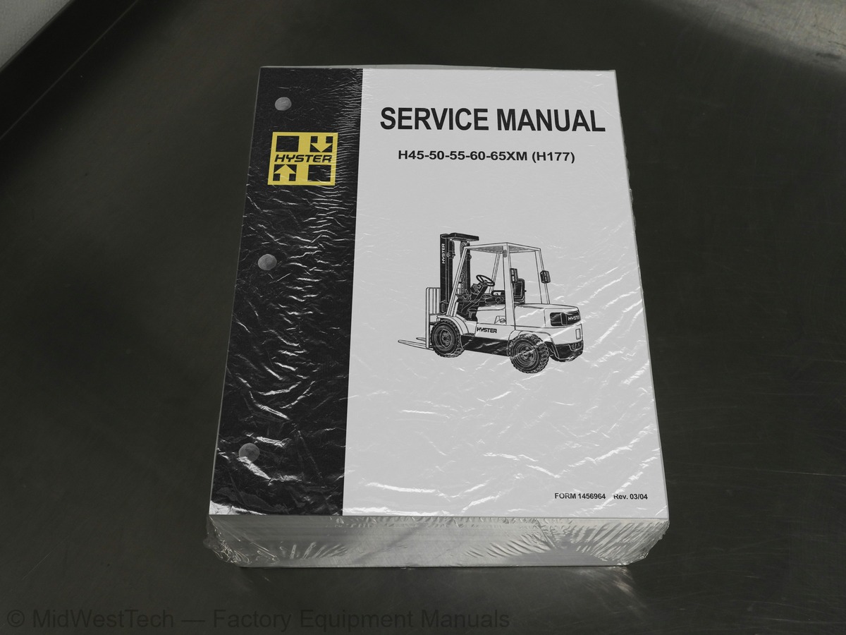
Hyster H45-50-55-60-65XM (H177) Forklift Service Manual
1,753 pages · Publication 1456964
Added to your cart. View cart
- Models
- H45-50-55-60-65XM (H177)
- Manual type
- Service Manual
- Pages
- 1,753
- Publication
- 1456964
- Condition
- Brand new
What's inside
From the manual's own table of contents: 333 sections, 700 entries. See sample pages (PDF, 299 KB)
Steering Axle Assembly Repair2 topics
- Remove
- Install
Wheels and Hubs Repair3 topics
- Remove and Disassemble
- Clean
- Assemble and Install
Steering Cylinder Repair1 topic
- Clean and Inspect
Cylinder Head, Camshaft, and Valve Mechanism Repair1 topic
- Inspect and Repair
Oil Pump Repair3 topics
- Disassemble
- Inspect
- Assemble
Cooling System Repair3 topics
- Thermostat
- Fan Assembly
- Water Pump
Flywheel and Ring Gear Repair S/H2.00-3.20XM (S/H40-65XM)1 topic
- Ring Gear, Replace
Throttle Linkage Adjustment3 topics
- Gasoline Engines
- LPG Engines (IMPCO)
- LPG Engines (AISAN)
Show all 333 sections
Engine Specifications9 topics
- Engine Data
- Cylinder Head
- Valve Mechanism
- Camshaft
- Crankshaft
- Connecting Rods
- Cylinder Block
- Pistons
- Oil Pump
Description and Operation8 topics
- General
- Torque Converter
- Clutch Assemblies
- Hydraulic System
- Control Valve
- MONOTROL® Pedal
- Direction Control Lever
- Differential
Oil Flow Diagrams4 topics
- Neutral
- Modulator Operation
- Forward
- Forward-Inching
Transmission Pump Repair1 topic
- Repair
Oil Pressure Checks5 topics
- Relief Valve for Transmission Pump Check, TEST PORT 1
- Clutch Pressure Check, TEST PORTS 2 and 3
- Torque Converter Regulator Check, TEST PORT 4
- Lubrication Circuit Oil Pressure Check, TEST PORT 5
- Modulator Pressure Check, TEST PORT 6
Overhead Guard Repair1 topic
- Remove and Install
Exhaust System Repair1 topic
- Muffler, Replace
Engine Repair4 topics
- Remove Engine Only
- Remove Engine and Transmission
- Install Engine Only
- Install Engine and Transmission
Fuel and Hydraulic Tanks Repair3 topics
- Small Leaks, Repair
- Large Leaks, Repair
- Additional Preparations for Repair
Brake System3 topics
- Service Brakes
- Master Cylinder
- Parking Brake
Service Brakes Repair1 topic
- Adjust
Instrument Cluster3 topics
- Display Panels on Steering Column, Internal Combustion
- Display Panels on Steering Column, Electric Lift Trucks
- Curtis 1215 Display Panel
Cluster Display Panel (Electric Lift Truck) Replacement7 topics
- Display Panel Assembly, Replace
- LED Indicators
- Battery Indicators
- Digital Display (Enhanced Display Panel Only)
- Status Code or Performance Level Switches and LED indicators (En
- Standard Display Panel Parts, Replace
- Enhanced Display Panel Parts, Replace
Mast2 topics
- Carriages
- Mast Mounts
Two-Stage Mast, Limited Free-Lift (LFL)1 topic
- Description and Operation
Carriages Repair6 topics
- Standard Carriage, Remove
- Hang-On Sideshift Carriage, Remove
- Standard Carriage and Hang-On Sideshift Carriage, Repair
- Standard Carriage, Install
- Hang-On Sideshift Carriage, Install
- Integral Sideshift Carriage
Mast Repair4 topics
- Two-Stage LFL and Two-Stage FFL Masts, Disassemble
- Three-Stage FFL Mast
- Two-Stage LFL and Two-Stage FFL Mast, Assemble
- Three-Stage FFL Mast, Assemble
Lift Cylinders Repair6 topics
- Main Lift Cylinders, Remove
- Free-Lift Cylinder, Remove
- Lift Cylinders, Disassemble
- Lift Cylinders, Assemble
- Main Lift Cylinders, Install
- Free-Lift Cylinder, Install
Header Hose Arrangements6 topics
- Two-Stage LFL Mast, New Hose Install
- Two-Stage LFL Mast, Adjust Hoses After Installation
- Two-Stage FFL Mast, New Hose Install
- Two-Stage FFL Mast, Adjust Hoses After Installation
- Three-Stage FFL Mast, New Hose Install
- Three-Stage FFL Mast, Adjust Hoses After Installation
Header Hose Arrangement1 topic
- Three-Stage FFL Mast, Adjust Hoses After Install
Lift and Tilt System Leak Check2 topics
- Lift Cylinders Leak Check
- Tilt Cylinders Leak Check
Electrical System3 topics
- Starting System
- Ignition System
- Charging System
Starter Checks5 topics
- Operation, Check
- Brush Holder, Check
- Armature, Check
- Field Windings, Check
- Clutch and Bearing, Check
Ignition System Check and Adjustment2 topics
- Engine Timing, Adjust
- Spark Plugs, Check
Charging Circuit Checks7 topics
- Low Output, Check
- High Output, Check
- Diodes, Check
- Rotor Field Winding, Check
- Stator Windings, Check
- Brushes and Bearings, Check
- Voltage Regulator, Check
Cooling System3 topics
- Radiator
- Radiator Cap
- Fan and Fan Shroud
Cooling System Checks1 topic
- Exhaust Leaks
Radiator Cleaning2 topics
- Drain
- Fill
Alternator with Regulator2 topics
- Alternator Type A
- Alternator Type B
Brushes Circuit Check2 topics
- Delco Alternators
- Motorola Alternators
Diode Bridge Check1 topic
- Delco and Leece-Neville Alternators
High Energy Ignition (HEI) System2 topics
- Install, If Crankshaft WAS NOT Rotated when Distributor was Remo
- Install, If Crankshaft WAS Rotated when Distributor was Removed
Ignition Coil Replacement2 topics
- Some Four- and Six-Cylinder Models
- V8, Some Four- and Six-Cylinder Models
Ignition Coil Check3 topics
- Coil in Distributor Cap Design
- Separate Coil Design
- Sensing Coil, Check
Tilt Cylinder Stroke and Mast Tilt Angle Adjustment2 topics
- Piston Rod Nut
- Retainer
Metric and Inch (SAE) Fasteners6 topics
- Threaded Fasteners
- Nomenclature, Threads
- Strength Identification
- Cotter (Split) Pins
- Fastener Torque Tables
- Conversion Table
General Safety Rules1 topic
- Lifting Engine
Cylinder Head Assembly Repair5 topics
- Description
- Valve Cover
- Rocker Assembly
- Valves and Valve Springs
- Valve Guides
Piston and Connecting Rod Assembly Repair3 topics
- Connecting Rod Bearings, Replace
- Piston and Connecting Rods
- Piston Rings
Crankshaft Assembly Repair5 topics
- Crankshaft Pulley
- Rear Oil Seal
- Thrust Washers
- Main Bearings
- Front and Rear Bearing Cap Seals, Install
Timing Case and Timing Gears Repair9 topics
- Timing Case
- Front Oil Seal
- Idler Gear
- Idler Gear Bushings, Replace
- Idler Gear Hub
- Camshaft Assembly, Fuel Injection Pump
- Camshaft Assembly, Valves
- Crankshaft Gear
- Timing Case Backplate
Engine Timing3 topics
- Set Timing of Number One Piston to Top Dead Center (TDC)
- Valve Timing, Check
- Fuel Pump Timing Check
Lubrication System Repair3 topics
- Oil Filter, Replace
- Oil Sump
- Relief Valve
Fuel System Repair13 topics
- Fuel Filter, Replace
- Fuel Injectors
- Fuel Pump
- Water Separator
- Fuel Injection Pump
- Fuel System Air Removal
- Governor Weight Assembly
- Engine Speed Control Assembly
- Fuel Injection Pump Linkage
- Record Maximum Fuel Position
- Electrical Stop Solenoid
- Thermostat, Replace
- Coolant Pump
Flywheel and Housing Repair2 topics
- Flywheel
- Flywheel Housing
Electrical System Repair15 topics
- Drive Belt
- Alternator
- Starter Motor
- Glow Plugs
- Cylinder Head Assembly
- Crankshaft Assembly
- Timing Case and Gear Assembly
- Engine Block Assembly
- Timing Data
- Lubrication System
- Fuel System
- Cooling System
- Electrical Equipment
- Piston and Connecting Rod Assemblies
- Timing Case and Drive Assembly
Periodic Maintenance3 topics
- Serial Number
- How to Move Disabled Lift Truck
- How to Put Lift Truck on Blocks
Maintenance Procedures Every 8 Hours or Daily2 topics
- How to Make Checks With Engine Stopped
- How to Make Checks With Engine Running
Maintenance Procedures Every 250 Hours or 6 Weeks10 topics
- Air Filter
- Engine Oil and Filter
- Brake Fluid
- Hydraulic Tank Breather
- Battery
- Forks
- Lift Chains
- Mast
- Steering Axle
- Cooling System, Clean Debris From Radiator Core
Maintenance Procedures Every 500 Hours or 3 Months2 topics
- Drain Tar From Aisan LPG Regulator
- PCV Valve
Maintenance Procedures Every 1000 Hours or 6 Months9 topics
- Diesel Fuel System
- Differential and Drive Axle, Powershift Transmission
- Valve Clearance, Check and Adjust
- Aisan Regulator Pressure/Diaphragm and O-Ring Checks
- Integral Sideshift Carriage, Check Bearings
- Control Levers and Pedals
- Cooling System, GM 3.0L EPA Compliant Engine
- LPG Fuel Filter (IMPCO), GM 3.0L EPA Compliant Engine, Replace
- Inspect Engine Electrical System, Connectors, and FCVS Connectio
Maintenance Procedures Every 2000 Hours or Yearly12 topics
- Powershift Transmission Oil and Filter
- LPG Fuel Filter Replace, (Pre-2004)
- Gasoline Fuel Filter
- Fuel Filter (Aisan LPG System), Replace
- LPG Fuel Injector (Aisan Closed-Loop Low Emission System)
- Integral Sideshift Carriage, Replace Bearings
- Oxygen Sensor, GM 3.0L EPA Compliant Engine
- Air Filter Element, GM 3.0L EPA Compliant Engine
- Inspect Low Pressure Regulator (LPR) for Oil Buildup and Leaks
- Check Throttle Shaft for Sticking
- Inspect Exhaust Manifold and Piping for Leaks
- Test LPG/GAS Regulator Pressure
Lift Chain Adjustments2 topics
- Lift Cylinder, Leak Check
- Tilt Cylinder, Leak Check
Wheel and Tire Replacement4 topics
- Solid Rubber Tire, Change S40-65XM Models
- Pneumatic Tire, Repair H45-65XM Models
- Add Air to Pneumatic Tires
- Solid Rubber Tire, Change H45-65XM Models
Tire Sizes2 topics
- Gasoline/LPG
- Diesel
Mast Speeds20 topics
- H40-65XM Mast Speeds (US Models) - Mazda M4-2.0G Engine
- H40-65XM Mast Speeds (US Models) - Mazda M4-2.2G Engine
- H40-65XM Mast Speeds (US Models) - GM 3.0L Engine
- H45-65XM Mast Speeds (US Models) - Perkins 704-26 (UB) Diesel En
- S45-65XM Mast Speeds (US Models) - Mazda M4-2.0G Engine
- S40-65XM Mast Speeds (US Models) - Mazda M4-2.2G Engine
- S40-65XM Mast Speeds (US Models) - GM 3.0L Engine
- H2.00-3.20XM Mast Speeds (European Models) - Mazda M4-2.0G Engin
- H2.00-3.20XM Mast Speeds (European Models) - Mazda M4-2.2G Engin
- H2.00-3.20XM Mast Speeds (European Models) - GM 3.0L Engine
- H2.00-3.20XM Mast Speeds (European Models) - Perkins 704-26 (UB)
- S2.00-3.20XM Mast Speeds (European Models) - Mazda M4-2.0G Engin
- S2.00-3.20XM Mast Speeds (European Models) - Mazda M4-2.2G Engin
- S2.00-3.20XM Mast Speeds (European Models) - GM 3.0L Engine
- Frame
- Brake System
- Steering System
- Drive Axle
- Transmission and Differential
- Engine - GM 3.0L
Steering Wheel and Column Assembly Repair5 topics
- Assembly Components, Remove
- Steering Control Unit, Disassemble
- Steering Control Unit, Clean
- Steering Control Unit, Assemble
- Assembly Components, Install
LPG Fuel System4 topics
- Fuel Tank
- Regulator
- Resonator
- Carburetor
Regulator Adjustment2 topics
- Regulator Height Adjustment
- Regulator Assembly Air Tightness Test
Carburetor Adjustment2 topics
- Idle Speed and Fuel Mixture
- Idle Control Adjustment
Governor Adjustment2 topics
- Checks
- Adjustments
Table 4. Idle Mixture Adjusting Screw1 topic
- Oxygen Sensor
Check Engine Light9 topics
- Inspect Warning Lamp
- Check Feedback Operation
- Check VAC1 and VAC2 Signals
- Check Resistor
- Check Fuel Injector
- Check Oxygen Sensor
- Check Vacuum Switch 1
- Check Vacuum Switch 2
- After Completing Checks
Electronic Engine Control14 topics
- Electronic Control Module (ECM)
- Electronic Engine Control
- Fuel Control
- ECM Sensors and Controllers
- Troubleshooting Procedure
- How This Section Is Arranged
- Where Do I Start?
- Visual/Physical Inspection
- Knowledge/Tools Required
- Damage From Static Discharge (Static Electricity)
- Troubleshooting Information
- ECM Diagnostic Codes Available
- SCAN Tool Information
- On-Board Diagnostic (OBD) System Check
Troubleshooting Charts1 topic
- Troubleshooting Chart Description Summary
A-1 No Malfunction Indicator Lamp3 topics
- Circuit Description
- Diagnostic Aids
- Test Description
Troubleshooting, Poor Operation14 topics
- Make a Careful Visual Check
- FAULT: Codes or Performance That Is Abnormal
- FAULT: Loss of Diagnostic Trouble Code (DTC) Memory
- FAULT: Engine Quits While Driving
- FAULT: Engine Is Difficult to Start
- FAULT: Variation in Engine Power When Throttle Is Held Steady
- FAULT: Decreased Engine Power
- FAULT: Detonation/Spark Knock
- FAULT: Engine Momentarily Does Not Increase Power When Throttle
- FAULT: One or More Cylinders Do Not Operate Correctly - Engine D
- FAULT: Rough Idle or Engine Stalls During Idle
- FAULT: Fuel Usage Too High
- FAULT: Dieseling
- FAULT: Backfire
System Test Charts3 topics
- Engine Coolant Temperature (ECT) Sensor Test
- Throttle Position (TP) Sensor Check
- Minimum Idle Speed
B-3 - Check Governor System3 topics
- Governor System Not Operating Correctly
- Check Function of Governor System
- Check PCV System
Fuel System Components Repair8 topics
- Fuel Pressure Relief Procedure
- Fuel Pump Replacement
- Throttle Body Injection Unit (TBI)
- Fuel Meter Body
- Fuel Injector
- Pressure Regulator
- Throttle Position Sensor (TPS)
- Idle Air Control (IAC) Valve
Governor System 3.0L Engine Repair4 topics
- Governor Module, Replace
- Governor Motor, Replace
- Throttle Cables, Install and Adjust
- MONOTROL® Pedal, Check
Governor System 4.3L Engine Repair2 topics
- Governor Throttle Drive Assembly
- Governor Drive Motor
Ignition System Components Repair3 topics
- ECM Replacement
- Function Check
- Distributor
Ignition Module Repair4 topics
- Test For Fault
- Replace
- Sensing Coil
- Ignition Coil
Sensors Repair2 topics
- Engine Coolant Temperature (ECT) Sensor, Replace
- MAP Sensor, Replace
Wiring3 topics
- Connectors and Terminals
- Procedures for Spark Plugs, Spark Plug Wires, and Boots
- Wiring Diagram
Cylinder Head and Valve Mechanism Repair9 topics
- Cylinder Head, Remove
- Cylinder Head, Disassemble
- Valves and Valve Seats
- Studs for Rocker Arms
- Hydraulic Valve Lifters
- Cylinder Head, Assemble
- Cylinder Head, Install
- Valve Clearance, Adjust
- Rocker Arm Cover, Install
Camshaft Repair6 topics
- Camshaft, Remove
- Camshaft, Clean and Inspect
- Camshaft Bearings, Remove
- Camshaft Bearings, Clean and Inspect
- Camshaft Bearings, Install
- Camshaft, Install
Inside this manual
Real pages from this service manual (1,753 pages). Open the sample pages (PDF, 298 KB)
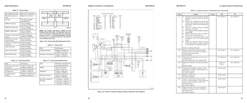
- Specifications, page 829: Engine Specifications
- Diagram, page 991: Diagrams, Schematics, or Arrangements
- Troubleshooting, page 1,342: A-7 Ignition System Troubleshooting
This is a service manual
Here's how it compares to the other manual types.
Service manual
Factory repair procedures and technical information such as specifications, troubleshooting, and wiring and hydraulic diagrams, for the models and systems the manual covers. See What's inside for its topics.
Operator's manual
Safe operation, controls, maintenance schedules, lubrication points, inspections, and basic checks. Repair procedures are in the service manual.
Parts manual
Illustrated diagrams with factory part numbers for identifying components and ordering parts. Repair procedures are in the service manual.
Engine service manuals are sometimes sold separately, since certain machine models were offered with more than one engine option.
What it's used for
Factory manual for in-house farm and construction shop use. Straightforward, complete, and easy to follow. It contains the OEM information dealership service departments and parts counters use to diagnose problems, identify components, and perform maintenance or repairs correctly.
Service shops and owner/operators who repair their own equipment
Identifying correct parts and seeing how assemblies come apart and go back together
Keeping equipment running with less downtime
Factory manual, 1,753 pages
Quantity one is the manual described above.
Fast free USA shipping
Ships in 1 business day.
60-day returns
Free if the mistake is ours. A manual ordered in error must come back unopened in its shrink-wrap; you pay return shipping and a 20% restocking fee applies. Return policy
Binder not included
Manuals over about 300 pages may need a standard 3-ring binder, which you can buy locally to keep the pages organized for shop use.
Other editions and similar models
Questions about model, serial number, engine coverage or contents? Contact us before purchasing and we'll help confirm it's the right manual. Please verify the manual type, machine model, serial number range and engine coverage before purchasing: manuals ordered in error carry a 20% restocking fee (return policy).