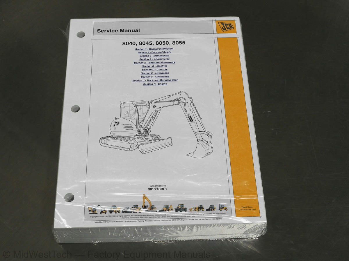
JCB 8040, 8045, 8050, 8055 Mini Excavator Service Manual
457 pages · Publication 9813-1850-1


Added to your cart. View cart
- Models
- 8040, 8045, 8050, 8055
- Serial coverage
- 8040ZTS from SN 1056000, 8045ZTS from SN 1057000, 8050ZTS from SN 1741500, 8050RTS from SN 1741500, 8055ZTS from SN 2060250, 8055RTS from SN 2060250
- Manual type
- Service Manual
- Pages
- 457
- Publication
- 9813-1850-1
- Condition
- Brand new
What's inside
From the manual's own table of contents: 3 sections, 254 entries. See sample pages (PDF, 322 KB)
Section 1 - General Information81 topics
- About this Manual
- Machine Model and Serial Number
- Using the Service Manual
- Section Numbering
- Left Side, Right Side
- Cross References
- Identification Plates
- Machine Identification Plate
- Typical Product Identification Number (PIN)
- Typical Engine Identification Number
- ROPS, TOPS and FOGS
- Zinc Plated Fasteners and Dacromet Fasteners
- Introduction
- Bolts and Screws
- Hydraulic Connections
- O' Ring Face Seal System
- Torque Stop' Hose System
- Numerical List
- Tool Detail Reference
- Section B - Frame and Bodywork
- Section C - Electrics
- Section E - Hydraulics
- Section K - Engine
- Sealing and Retaining Compounds
- Colour Coding
- Hydraulic Schematic Colour Codes
- Important Information
- The Operator Manual
- Safety Warnings
- Safety Check List
- Safety - Yours and Others
- General Safety
- Operating Safety
- Maintenance Safety
- Safety Labels
- Safety Label Identification
- Service Requirements
- Owner/Operator Support
- Service/Maintenance Agreements
- Fit for Purpose Tests for Lifting Equipment
- Obtaining Replacement Parts
- Health and Safety
- Lubricants
- Battery
- Service Schedules
- How to Use the Service Schedules
- Calendar Equivalents
- Pre-Start Cold Checks, Service Points and Fluid Levels
- Functional Test and Final Inspection
- Fluids, Lubricants and Capacities
- Coolant Mixtures
- Fuels
- Tools
- Toolbox (if fitted)
- Carrying Tools onto the Machine
- Prepare the Machine for Maintenance
- How to Make the Machine Safe (Excavator Lowered)
- Cleaning the Machine
- Preparing the Machine for Cleaning
- Cleaning the Tracks
- Checking for Damage
- Check the Machine Body and Structure
- Check the Seat and Seat Belt
- Check the Hydraulic Hoses and Fittings
- Check the Electrical Circuits
- Checking the ROPS/FOPS Structure
- Checking the Ram Piston Rods
- Greasing
- Pivot Pins
- Slew Ring Bearings
- Slew Ring Gear Teeth
- Access Panels
- Engine Cover
- Hydraulic Bay Cover
- Electrical System
- Fuses
- Engine
- Oil and Filter
- Cooling System
- Fan Belt
- Air Filter
Section 3 - Maintenance121 topics
- Fuel System
- Water Separator and Engine Fuel Filter
- Bleeding the System
- Hydraulic System
- Releasing the Hydraulic Pressure
- Tracks and Running Gear
- Checking the Track Gearbox Oil Level
- Changing the Track Gearbox Oil
- Checking the Track Tension
- Windscreen Washer
- Checking the Level
- Fire Extinguisher (if fitted)
- Checking the Fire Extinguisher
- Attachments For Your Machine
- Impact Protection
- Connecting/Disconnecting Hydraulic Hoses
- Connecting the Hydraulic Hoses
- Disconnecting the Hydraulic Hoses
- Quick Release Couplings
- Manual Quickhitch
- Installation
- Removal
- Maintenance
- Buckets
- Bucket Selection
- Removing a Bucket - Non Quickhitch Models
- Installing a Bucket - Non Quickhitch Models
- Removing a Bucket from a Quickhitch
- Installing a Bucket on a Quickhitch
- Replacing Bucket Teeth
- Quickhitch Rockbreaker
- Removing a Quickhitch Rockbreaker
- Installing a Quickhitch Rockbreaker
- Operation
- Rivet Nuts
- Fitting Procedure
- Glazing
- Direct Glazing
- Removal and Replacement
- Replacement
- Inspection
- Checking Slew Bearing Backlash
- Checking Slew Bearing Vertical Lift
- General Electrical Data
- Using a Multimeter
- Measuring DC Voltage
- Measuring Resistance
- Measuring Continuity
- Measuring Frequency
- Testing a Diode or a Diode Wire
- Alternator
- General Description
- Service Precautions
- Charging Circuit Test
- Alternator Charging Test
- Starter Motor
- Starting Circuit Test
- First Aid - Electrolyte
- Testing
- Specific Gravity Testing
- Wiring Harness Repair
- Repair Procedure
- Machines Built Up to September 2006
- Component Key
- Tier 2 Machines Built September 2006 to January 2008
- Tier 3 Machines Built January 2008 to December 2010
- tion)
- Wire and Harness Number Identification
- Wire Numbers and Functions
- Mainframe Harness - Machines Built up to September 2006
- Drawings
- Mainframe Harness - Tier 3 Machines Built January 2011 Onwards
- Controls Identification
- Servo Hand Controllers
- Leakage Amount
- Spool
- Plunger
- Loose Movement in the Operating Controls
- Actuation Stability
- Dismantling and Assembly
- Dismantling
- Assembly
- Fault Finding
- Track Controls
- Dozer Controls
- Mechanical Throttle (Machines up to end of February 2012)
- Cable Adjustment and Calibration
- Electronic Throttle System (Machines from March 2012)
- Electronic Throttle Control Module (ECM)
- Magnetic Speed Sensor
- ECG Actuator
- Mounting Kit and Isolators
- System Adjustments
- Flash Error Codes
- Standard Machine (No options)
- Option 1 (9 Spools electroproportional)
- Option 2 (10 Spools single electroproportional)
- All Machines
- Introduction to Hydraulic Schematic Symbols
- General (Basic and Functional Symbols)
- Control Valves
- Example of Schematic Circuit
- Hydraulic Contamination
- Hydraulic Fluid Quality
- Effects of Contamination
- Cleaning Operation
- Contaminant Standards
- Filters
- All Machines (Up to December 2010)
- Hose Colour Data
- Neutral Circuit
- Main Services Circuit
- Traction Circuit
- Slew Circuit
- Spool Standard Machine
- Spool Electroproportional Control Machines
- General Fault Diagnosis
- Slew Motor and Gearbox
- Testing and Setting
- Removal and Inspection
- Description
Section E - 149 topics
- Setting Servo Pressure
- Testing the P.M.V
- Setting the Pressure Control Valve
- Setting the Flow Control Valve
- External Components
- Internal Components
- Hydraulic Motor Section
- Two Speed Motor Operation
- Hydraulic Valve Section
- Parking Brake Section
- Track Motor
- Track Gearbox
- Brake Valve
- Shockless Relief Valve Section
- Check Valve Section
- Parking Brake Timer Valve Section
- Slew Motor
- Slew Gearbox
- Parking Brake Timer Valve
- Cross Line Relief Valve
- Component Locations
- Schematics
- Regeneration
- Dismantling, Inspection and Assembly
- Control Valve Sections
- Inlet/Outlet
- Slew
- Boom
- Auxiliary
- Bucket
- Dipper
- Dozer
- Swing
- Track Right
- Track Left
- Precautions During Use
- Caution During Use
- Maintenance, Inspection Points
- Boom, Dipper and Bucket Rams
- Dozer Ram
- Swing Ram
- All Rams
- Technical Data
- Major Component Torque Settings
- Lower Rollers
- Upper Rollers
- Track Roller Metallic Face Seals
- When Removing
- When Replacing
Inside this manual
Real pages from this service manual (457 pages). Open the sample pages (PDF, 322 KB)
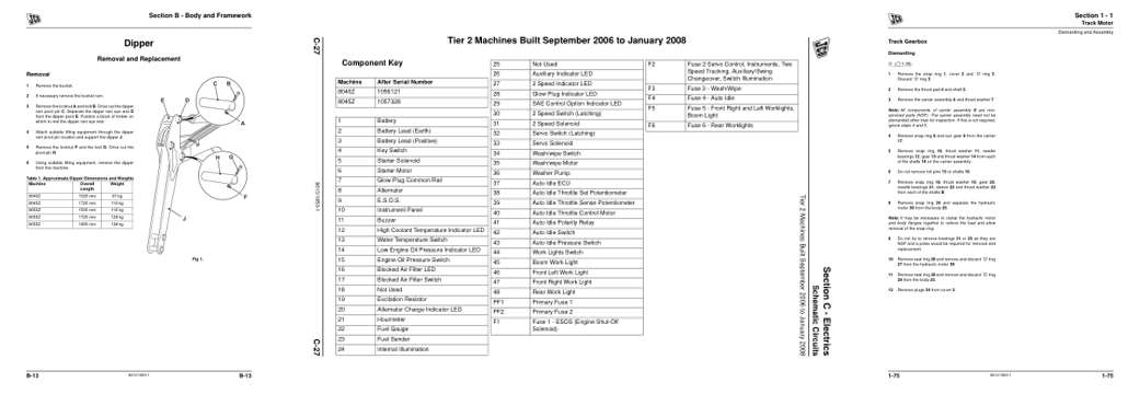
- Specifications, page 154: Section B - Body and Framework
- Diagram, page 196: Section C - Electrics
- Repair procedure, page 350: Track Motor
This is a service manual
Here's how it compares to the other manual types.
Service manual
Factory repair procedures and technical information such as specifications, troubleshooting, and wiring and hydraulic diagrams, for the models and systems the manual covers. See What's inside for its topics.
Operator's manual
Safe operation, controls, maintenance schedules, lubrication points, inspections, and basic checks. Repair procedures are in the service manual.
Parts manual
Illustrated diagrams with factory part numbers for identifying components and ordering parts. Repair procedures are in the service manual.
Engine service manuals are sometimes sold separately, since certain machine models were offered with more than one engine option.
What it's used for
Factory manual for in-house farm and construction shop use. Straightforward, complete, and easy to follow. It contains the OEM information dealership service departments and parts counters use to diagnose problems, identify components, and perform maintenance or repairs correctly.
Service shops and owner/operators who repair their own equipment
Identifying correct parts and seeing how assemblies come apart and go back together
Keeping equipment running with less downtime
Factory manual, 457 pages
Quantity one is the manual described above.
Fast free USA shipping
Ships in 1 business day.
60-day returns
Free if the mistake is ours. A manual ordered in error must come back unopened in its shrink-wrap; you pay return shipping and a 20% restocking fee applies. Return policy
Binder not included
Manuals over about 400 pages may need a standard 3-ring binder, which you can buy locally to keep the pages organized for shop use.
Other editions and similar models
Questions about model, serial number, engine coverage or contents? Contact us before purchasing and we'll help confirm it's the right manual. Please verify the manual type, machine model, serial number range and engine coverage before purchasing: manuals ordered in error carry a 20% restocking fee (return policy).