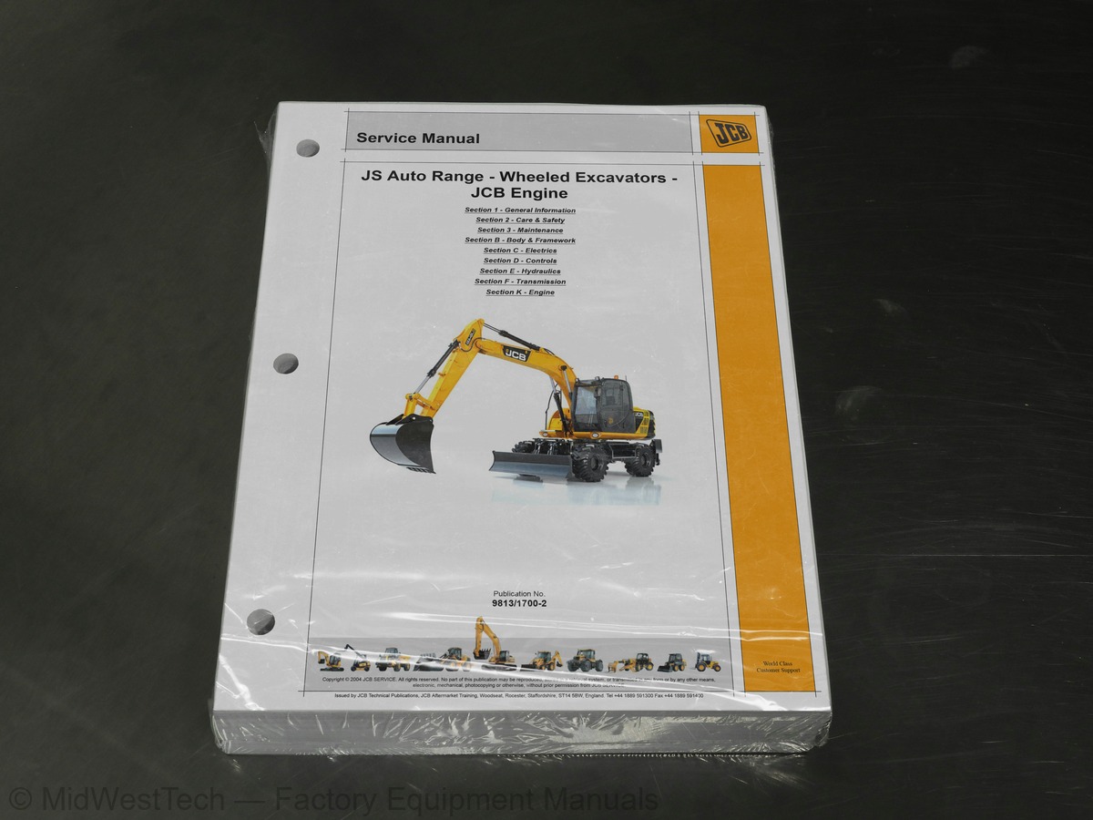
JCB JS Auto Range JS145W, JS160W Wheeled Excavator Service Manual
812 pages · Publication 9813-1700-2
Added to your cart. View cart
- Models
- JS Auto Range JS145W, JS160W
- Serial coverage
- JS145W from SN 01786864 to 01788884, JS160W from SN 01789228 to 01789428
- Manual type
- Service Manual
- Pages
- 812
- Publication
- 9813-1700-2
- Condition
- Brand new
What's inside
From the manual's own table of contents: 207 topics. See sample pages (PDF, 389 KB)
- About this Manual
- Identifying Your Machine
- Zinc Plated Fasteners and Dacromet Fasteners
- Hydraulic Connections
- Numerical List
- Tool Detail Reference
- Sealing and Retaining Compounds
- Colour Coding
- Service Requirements
- Health and Safety
- Service Schedules
- Fluids, Lubricants and Capacities
- Tools
- Prepare the Machine for Maintenance
- Cleaning the Machine
- Check the Machine for Damage
- Daily Checking
- Greasing
- Tyres and Wheels
- Electrical System
- Bolt and Nut Torque Specifications
- Engine
- Fuel System
- Hydraulic System
Show all 207 topics
- Slew Gearbox
- Drive Gearbox
- Axles
- Bucket
- Windscreen Washer
- Fire Extinguisher (If fitted)
- Troubleshooting
- Static Dimensions
- Dig Depth Chart
- Shipping Weight
- Tyre Pressures
- Air Conditioning (option)
- Automatic Temperature Control (ATC) System
- Air Conditioning
- HVAC/Air Conditioning Unit
- Air Conditioning Compressor
- Cab Structure
- Cab Panel Removal
- Circuit Symbols
- Component Identification
- Schematic Diagram
- A.M.S (Advanced Management System)
- Circuit Concepts
- Pulse Width Modulation (PWM)
- ECU 1 Supply to Output Drivers
- ECU W Supply to Output Drivers
- ECU W / LH Switch Panel Supply and Network
- Hardware Sensing
- Engine Throttle Control
- Pump Control for Each Mode
- Auto Boost Pressure
- Engine Oil Level Warning
- Engine Automatic Warm Up
- Engine Automatic Idle
- Engine One Touch Idle
- Engine Start/Stop
- Engine Cranking
- Alternator/No Charge Warning
- Limp Mode system
- Lever Lock
- Servo Isolator
- Wiper
- Lower Wiper (option)
- Washer
- Horn
- Travel Alarm
- Soft/Hard (Cushion)
- Slew lock (100% Slew Brake)
- Travel Mode
- Cruise Control - Optional
- Park Brake
- Speed Travel
- Work Lights (Boom and Cab)
- Head Lights
- Side Lights
- Brake Lights
- Indicators
- Fog/Reversing Lights
- Hazard Warning
- Axle Lock
- Stabilisers
- Dozer
- Viscous Fan
- Fuel Level Sensor/Warning
- Engine Temperature Sensor/Warning
- Coolant Level Warning
- Air Filter Blocked Warning
- Warning Indicator Lamps
- Hydraulic Temperature Sensor/Warning
- Brake Pressure Warning
- Engine Oil Pressure/Emergency Steering Warning
- Quick hitch (option)
- Overload Caution (option)
- Beacon
- Grab/rotate
- Hammer Only
- Scrap Magnet Option
- Cab Interior Lamp
- Refuelling Pump
- Heated Seat
- to 12 Volt Converter, Radio and Power Socket
- Service Required Warning
- EMS Set Menu
- EMS Set + Mode Menu
- EMS Set+Mode (20 sec) Menu
- JCB Servicemaster
- Testing of ECU Inputs + Outputs
- Using a Multimeter
- Battery
- Wiring Harness Repair
- Main/Wheeled Harness
- Fascia Link Harness
- Cab Harness (Includes Engine Harness)
- General Data
- Hydraulic Component Location
- Introduction to Hydraulic Schematic Symbols
- Hydraulic Schematic
- Servo Line
- Servo Pressure and Return Line
- Transmission Pilot Line
- Chassis Hydraulics
- Monoboom Hammer/Aux Hydraulics
- Tab Hammer/Aux Hydraulics
- Hydraulic Pump Operation
- Hydraulic Pump Regulation
- Neutral Circuit
- Drive
- Boom Up
- Boom Down
- Dipper In
- Dig End Isolate
- Bucket Close
- Slew Circuit
- 100% Slew Lock
- Auxiliary Flow
- Hammer
- ISO/SAE Controls
- Gear Change
- Cruise Control (Optional)
- Stabiliser and Dozer
- Brake and Steering
- Grab Rotate
- Axle Lock Rams
- Description
- Port Identification
- Hydraulic Pump Removal and Replacement
- Hydraulic Pump Dismantling and Assembly
- Regulator Dismantling and Assembly
- Operation
- Removal and Replacement
- Dismantling and Assembly
- Motor Operating Principles
- Slew Brake Operation
- Fault Finding
- Slew Motor Configuration
- Slew Motor Dismantling and Assembly
- Reduction Gear Structure and Working Principles
- Gearbox Dismantling and Assembly
- Control Unit
- Priority Valve
- Precautions During Use
- Maintenance Specifications
- Make the Machine Safe
- Pressure Testing - General
- Pressure Relief Valve Location
- Main Relief Valve (MRV) Pressure
- Servo Relief Pressure
- Slew Motor Pressure Relief
- Auxiliary Relief Valves
- Dozer/Stabilisers
- Brake Service Pressure
- Steer Stall System Pressure
- Hydraulic Contamination
- Main Control Valve
- Relief Valve
- Slew Motor
- Hydraulic Pump
- Hydraulic Rams
- Fault Finding Tests
- Test 001: Testing Negative Control Signal
- Test 002: Test Max Flow Signal/Drive Control Signal
- Test 003: Testing Main Pump Pressure
- Test 004: Testing Horsepower Control
- Test 005: Checking the Operation of the Main Hydraulic Spool
- Test 006: Testing Pressure Switches
- Test 007: Testing Engine Speed Settings
- Test 008: Testing Machine Cycle Times
- Test 011: Testing Swing brake pressure
- Test 016: Flow testing Hydraulic Pumps
- Test 017: Testing Slew Bearing
- Test 018: Testing Pump Milliamps
- Test 019: Testing Latch Brake Pressure
- Test 020: Testing for Trapped Air in HBCV Pilot Line
- Test 021: Testing the Operation of the Arm 2 Boost Spool
- Test 022: Testing Drive Motor Threshold Pressure
- Test 023: Checking Drive Motor Displacement
- Test 024: Testing Propshaft RPM
- Test 025: Testing Clutch Pack Pressure/Park Brake Pressure
- Test 026: Testing Condition of On Road Clutch
- Ram Creep Tests - All Services
- Technical Data
- Unit Identification
- Dismantle and Assembly
Inside this manual
Real pages from this service manual (812 pages). Open the sample pages (PDF, 388 KB)

- Specifications, page 167: Section B - Body and Framework
- Diagram, page 455: Circuit Descriptions
- Repair procedure, page 671: Hydraulic Rams
- Color page, page 358: Section C - Electrics
- Color page, page 578: Section E - Hydraulics
This is a service manual
Here's how it compares to the other manual types.
Service manual
Factory repair procedures and technical information such as specifications, troubleshooting, and wiring and hydraulic diagrams, for the models and systems the manual covers. See What's inside for its topics.
Operator's manual
Safe operation, controls, maintenance schedules, lubrication points, inspections, and basic checks. Repair procedures are in the service manual.
Parts manual
Illustrated diagrams with factory part numbers for identifying components and ordering parts. Repair procedures are in the service manual.
Engine service manuals are sometimes sold separately, since certain machine models were offered with more than one engine option.
What it's used for
Factory manual for in-house farm and construction shop use. Straightforward, complete, and easy to follow. It contains the OEM information dealership service departments and parts counters use to diagnose problems, identify components, and perform maintenance or repairs correctly.
Service shops and owner/operators who repair their own equipment
Identifying correct parts and seeing how assemblies come apart and go back together
Keeping equipment running with less downtime
Factory manual, 812 pages
Quantity one is the manual described above.
Fast free USA shipping
Ships in 1 business day.
60-day returns
Free if the mistake is ours. A manual ordered in error must come back unopened in its shrink-wrap; you pay return shipping and a 20% restocking fee applies. Return policy
Binder not included
Manuals over about 300 pages may need a standard 3-ring binder, which you can buy locally to keep the pages organized for shop use.
Other editions and similar models
Questions about model, serial number, engine coverage or contents? Contact us before purchasing and we'll help confirm it's the right manual. Please verify the manual type, machine model, serial number range and engine coverage before purchasing: manuals ordered in error carry a 20% restocking fee (return policy).