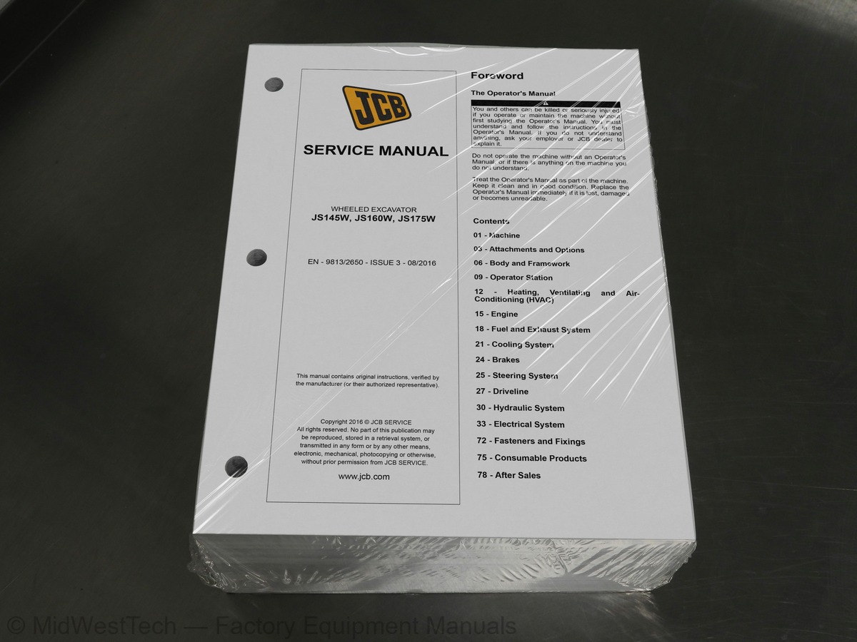
JCB JS145W, JS160W, JS175W Wheeled Excavator Service Manual
1,808 pages · Publication 9813-2650
Added to your cart. View cart
What's inside
From the manual's own table of contents: 14 sections, 107 entries. See sample pages (PDF, 397 KB)
01 - Machine12 topics
- Acronyms Glossary
- 01-03-03 Safety - Yours and Others
- 01-03-06 Safety Warnings
- 01-03-09 General Safety
- 01-03-12 Maintenance Safety
- 01-03-18 Operating Safety
- 01-03-21 Worksite Safety
- 01-03-24 Risk Assessment
- 01-03-27 Maintenance Positions
- 01-06-06 Using the Manual
- 01-09-12 Main Component Locations
- 01-09-15 Service Point Locations
03 - Attachments and Options1 topic
- 03-10-06 Hydraulic Quickhitch
06 - Body and Framework4 topics
- 06-06-06 Engine Compartment
- 06-06-09 Hydraulic Compartment
- 06-15-15 Tipping Linkage
- 06-63-15 Operator Protective Structure
09 - Operator Station4 topics
- 09-00-06 Operator Protective Structure
- 09-27-01 Controls Isolation
- 09-27-54 Service Brake Pedal
- 09-30-12 Side Console Trim
12 - Heating, Ventilating and18 topics
- 15-51-03 Crankshaft Gear
- 15-51-09 Fuel Injection Pump Gear
- 15-51-15 Heavy Duty PTO Gear
- 15-84-03 Crankshaft Position
- 15-84-06 Camshaft Position
- 15-84-14 Exhaust Manifold Temperature
- 15-84-16 Exhaust Manifold Pressure
- 15-84-17 Temperature and Manifold Air Pressure (TMAP)
- 15-84-18 Temperature and Mass Air Flow (TMAF)
- 15-84-19 Exhaust Temperature
- 15-84-24 Fuel Temperature
- 15-84-27 Fuel Rail Pressure
- 15-84-33 Coolant Temperature
- 15-84-42 Engine Oil Temperature
- 15-84-48 Intercooler Outlet Temperature
- 15-87-03 Engine Oil Pressure
- 15-87-18 Air Filter Vacuum
- 15-87-43 Engine Oil Level
18 - Fuel and Exhaust System7 topics
- 18-00-30 Throttle Control System
- 18-09-09 Pre-Filter Element
- 18-12-04 Water in Fuel Sensor
- 18-24-03 Inlet Manifold
- 18-24-04 Outlet Manifold
- 18-96-03 High Pressure Pipe
- 18-96-06 Low Pressure Pipe
21 - Cooling System2 topics
- 21-03-18 Viscous Coupling
- 24-03-57 Pressure Sensor
30 - Hydraulic System12 topics
- 30-00-15 Parallel Open Centre System
- 30-00-49 Schematic Symbols
- 30-00-50 Schematic Circuit
- 30-03-12 Suction Strainer
- 30-04-10 Auxiliary Return Line
- 30-15-19 Triple Articulated Boom (TAB)
- 30-50-03 Main Relief Valve (MRV)
- 30-50-06 Auxiliary Relief Valve (ARV)
- 30-60-27 Auxiliary Circuit
- 30-60-44 Transmission
- 30-60-96 Control Pattern Selector
- 30-97-03 Quick Release Coupling
33 - Electrical System28 topics
- 33-00-50 Schematic Circuit
- 33-03-03 Isolator Switch
- 33-09-09 Primary Fusebox
- 33-09-12 Secondary Fusebox
- 33-12-12 Operator Station
- 33-12-24 Auxiliary Hydraulic Circuit
- 33-12-57 Heating, Ventilating and Air-Conditioning (HVAC)
- 33-15-06 Object Handling
- 33-27-06 Direction Indicators
- 33-27-12 Heating, Ventilating and Air-Conditioning (HVAC)
- 33-27-15 Hand Throttle Control
- 33-27-16 Throttle Auto-Idle
- 33-27-17 Throttle One Touch-Idle
- 33-27-24 Transmission Mode
- 33-33-08 Hazard Warning Lights
- 33-33-15 Transmission Disconnect
- 33-33-26 Front Window Washer/Wiper
- 33-33-36 Control Lever Lock
- 33-33-94 Control Pattern Selector
- 33-42-06 Front Side Light
- 33-42-12 Front Direction Indicator
- 33-42-22 Rear Brake Light
- 33-42-24 Reverse Light / Rear Fog Light
- 33-42-27 Rear Direction Indicator
- 33-42-33 Number Plate Light
- 33-45-01 Instrument Panel
- 33-84-06 Hydraulic Oil Temperature
- 33-84-12 Ambient Air Temperature
75 - Consumable Products2 topics
- 75-03-21 Refrigerant
- 75-09-12 Diesel Exhaust Fluid (DEF)
78 - After Sales3 topics
- 78-24-03 Maintenance Intervals
- 78-24-06 Pre-start Cold Checks, Service Points and Fluid Levels
- 78-24-09 Functional Tests and Final Inspection
Inside this manual
Real pages from this service manual (1,808 pages). Open the sample pages (PDF, 396 KB)
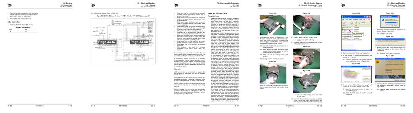
- Repair procedure, page 264: 15 - Engine
- Diagram, page 1,290: 50 - Schematic Circuit
- Specifications, page 1,749: 75 - Consumable Products
- Color page, page 1,017: 30 - Hydraulic System
- Color page, page 1,633: 33 - Electrical System
This is a service manual
Here's how it compares to the other manual types.
Service manual
Factory repair procedures and technical information such as specifications, troubleshooting, and wiring and hydraulic diagrams, for the models and systems the manual covers. See What's inside for its topics.
Operator's manual
Safe operation, controls, maintenance schedules, lubrication points, inspections, and basic checks. Repair procedures are in the service manual.
Parts manual
Illustrated diagrams with factory part numbers for identifying components and ordering parts. Repair procedures are in the service manual.
Engine service manuals are sometimes sold separately, since certain machine models were offered with more than one engine option.
What it's used for
Factory manual for in-house farm and construction shop use. Straightforward, complete, and easy to follow. It contains the OEM information dealership service departments and parts counters use to diagnose problems, identify components, and perform maintenance or repairs correctly.
Service shops and owner/operators who repair their own equipment
Identifying correct parts and seeing how assemblies come apart and go back together
Keeping equipment running with less downtime
Factory manual, 1,808 pages
Quantity one is the manual described above.
Fast free USA shipping
Ships in 1 business day.
60-day returns
Free if the mistake is ours. A manual ordered in error must come back unopened in its shrink-wrap; you pay return shipping and a 20% restocking fee applies. Return policy
Binder not included
Manuals over about 300 pages may need a standard 3-ring binder, which you can buy locally to keep the pages organized for shop use.
Other editions and similar models
Questions about model, serial number, engine coverage or contents? Contact us before purchasing and we'll help confirm it's the right manual. Please verify the manual type, machine model, serial number range and engine coverage before purchasing: manuals ordered in error carry a 20% restocking fee (return policy).