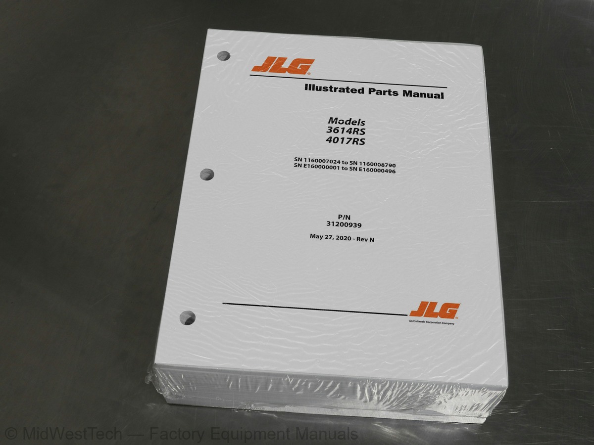
JLG 3614RS, 4017RS Telehandler Parts Manual
1,262 pages · Publication 31200939
Added to your cart. View cart
What's inside
From the manual's own table of contents: 13 sections, 379 entries. See sample pages (PDF, 601 KB)
SECTION 1 - FRAME AND ATTACHING PARTS25 topics
- FIGURE 1-1. FRAME INSTALLATION - 3614RS
- FIGURE 1-2. FRAME INSTALLATION - 3614RS
- FIGURE 1-4. FRAME INSTALLATION - 4017RS (74KW)
- FIGURE 1-5. FRAME INSTALLATION - 4017RS (74KW)
- FIGURE 1-6. FRAME INSTALLATION - 4017RS (55KW)
- FIGURE 1-7. FRAME INSTALLATION - 4017RS (55KW)
- FIGURE 1-10. ENCLOSURE GROUP INSTALLATION
- FIGURE 1-11. MIRROR INSTALLATION - 3614RS
- FIGURE 1-12. MIRROR INSTALLATION - 4017RS
- FIGURE 1-13. REAR MIRROR INSTALLATION
- FIGURE 1-14. MIRROR ASSEMBLY
- FIGURE 1-15. BOOM PROP INSTALLATION
- FIGURE 1-16. WHEEL CHOCK INSTALLATION
- FIGURE 1-17. COUNTERWEIGHT INSTALLATION - 3614RS
- FIGURE 1-18. COUNTERWEIGHT INSTALLATION - 4017RS
- FIGURE 1-19. HOOD ASSEMBLY
- FIGURE 1-20. SOUND SUPPRESSION INSTALLATION (LCAD, AFRICA AND MID EAST, PAC RIM)
- FIGURE 1-21. SOUND SUPPRESSION INSTALLATION (EU, GERMANY, FRANCE, UK AND IRELAND)
- FIGURE 1-23. CHASSIS COVER PLATE INSTALLATION - 3614RS
- FIGURE 1-24. CHASSIS COVER PLATE INSTALLATION - 4017RS
- FIGURE 1-25. LICENSE PLATE INSTALLATION
- FIGURE 1-26. RETRIEVAL HITCH
- FIGURE 1-27. HYDRAULIC TANK INSTALLATION
- FIGURE 1-28. PAD LOCK
- FIGURE 1-29. HITCH PIN ASSEMBLY
SECTION 2 - BOOM44 topics
- FIGURE 2-1. BOOM INSTALLATION - 3614RS (NO AUXILIARY HYDRAULICS)
- FIGURE 2-2. BOOM INSTALLATION - 3614RS (AUXILIARY HYDRAULICS)
- FIGURE 2-3. BOOM INSTALLATION - 4017RS (NO AUXILIARY HYDRAULICS)
- FIGURE 2-4. BOOM INSTALLATION - 4017RS (AUXILIARY HYDRAULICS)
- FIGURE 2-5. BOOM ASSEMBLY - 3614RS (NO AUXILIARY HYDRAULICS)
- FIGURE 2-6. BOOM ASSEMBLY - 3614RS (AUXILIARY HYDRAULICS)
- FIGURE 2-7. BOOM ASSEMBLY - 4017RS (NO AUXILIARY HYDRAULICS)
- FIGURE 2-8. BOOM ASSEMBLY - 4017RS (AUXILIARY HYDRAULICS)
- FIGURE 2-9. EXTEND CHAIN ASSEMBLY - 3614RS
- FIGURE 2-10. EXTEND CHAIN ASSEMBLY (1) - 4017RS
- FIGURE 2-11. EXTEND CHAIN ASSEMBLY (2) - 4017RS
- FIGURE 2-12. RETRACT CHAIN ASSEMBLY - 3614RS
- FIGURE 2-13. RETRACT CHAIN ASSEMBLY (1) - 4017RS
- FIGURE 2-14. RETRACT CHAIN ASSEMBLY (2) - 4017RS
- FIGURE 2-15. COVER PLATE INSTALLATION - 3614RS
- FIGURE 2-16. COVER PLATE INSTALLATION - 4017RS
- FIGURE 2-17. FIRST BOOM SECTION - 3614RS
- FIGURE 2-18. FIRST BOOM SECTION - 4017RS
- FIGURE 2-19. SECOND BOOM SECTION - 3614RS
- FIGURE 2-20. SECOND BOOM SECTION - 4017RS
- FIGURE 2-21. THIRD BOOM SECTION - 3614RS
- FIGURE 2-22. THIRD BOOM SECTION - 4017RS
- FIGURE 2-23. FOURTH BOOM SECTION - 4017RS
- FIGURE 2-24. HOSE SUPPORT ASSEMBLY - 4017RS
- FIGURE 2-25. MANUAL QUICK ATTACH
- FIGURE 2-26. HYDRAULICS INSTALLATION - 3614RS (NO AUXILIARY HYDRAULICS)
- FIGURE 2-27. HYDRAULICS INSTALLATION - 3614RS (AUXILIARY HYDRAULICS)
- FIGURE 2-28. HYDRAULICS INSTALLATION - 4017RS
- FIGURE 2-29. HYDRAULICS ASSEMBLY - 4017RS
- FIGURE 2-30. HYDRAULICS INSTALLATION - 4017RS (AUXILIARY HYDRAULICS)
- FIGURE 2-31. AUXILIARY LINES INSTALLATION
- FIGURE 2-32. BOOM BRUSH INSTALLATION - 3614RS
- FIGURE 2-33. BOOM BRUSH INSTALLATION - 4017RS
- FIGURE 2-34. BOOM BRUSH BRACKET ASSEMBLY (1)
- FIGURE 2-35. BOOM BRUSH BRACKET ASSEMBLY (2)
- FIGURE 2-36. BOOM BRUSH BRACKET ASSEMBLY (3)
- FIGURE 2-37. BOOM BRUSH BRACKET ASSEMBLY (4) - 3614RS
- FIGURE 2-38. BOOM BRUSH BRACKET ASSEMBLY (5) - 3614RS
- FIGURE 2-39. BOOM BRUSH BRACKET ASSEMBLY (6)
- FIGURE 2-40. BOOM BRUSH BRACKET ASSEMBLY (7) - 4017RS
- FIGURE 2-41. BOOM BRUSH BRACKET ASSEMBLY (8) - 4017RS
- FIGURE 2-42. BOOM BRUSH BRACKET ASSEMBLY (9) - 4017RS
- FIGURE 2-43. BOOM BRUSH BRACKET ASSEMBLY (10) - 4017RS
- FIGURE 2-44. BOOM BRUSH BRACKET ASSEMBLY (11) - 4017RS
SECTION 3 - ATTACHMENTS27 topics
- FIGURE 3-1. CARRIAGE
- FIGURE 3-2. FORKS
- FIGURE 3-3. FORKS TINES
- FIGURE 3-10. INSTALLATION, CARRIAGE FORK POSITIONING
- FIGURE 3-11. INSTALLATION, FORK AND HOOK - 3614RS
- FIGURE 3-12. INSTALLATION, FORK AND HOOK - 4017RS
- FIGURE 3-13. 4 TON FORK HOOK
- FIGURE 3-14. STANDARD CARRIAGE INSTALLATION WITH LIFT LUG - 3614RS
- FIGURE 3-15. STANDARD CARRIAGE INSTALLATION WITH LIFT LUG - 4017RS
- FIGURE 3-16. 4T FORK AND HOOK CARRIAGE
- FIGURE 3-17. MANITOU CARRIAGE INSTALLATION - 3614RS
- FIGURE 3-18. MANITOU CARRIAGE INSTALLATION - 4017RS
- FIGURE 3-19. MANITOU COUPLER INSTALLATION
- FIGURE 3-20. MANITOU CARRIAGE
- FIGURE 3-21. JCB CARRIAGE INSTALLATION - 3614RS
- FIGURE 3-22. JCB CARRIAGE INSTALLATION - 4017RS
- FIGURE 3-23. JCB COUPLER INSTALLATION
- FIGURE 3-24. JCB COUPLING
- FIGURE 3-25. JCB FORK ASSEMBLY
- FIGURE 3-26. SIDE SHIFT CARRIAGE INSTALLATION - 3614RS
- FIGURE 3-27. SIDE SHIFT CARRIAGE INSTALLATION - 4017RS
- FIGURE 3-30. FORK TRANSPORT LATCH INSTALLATION
- FIGURE 3-31. HOMOLOGATION INSTALLATION - 3614RS (GERMANY)
- FIGURE 3-32. HOMOLOGATION WARNING PANEL INSTALLATION - 3614RS (GERMANY)
- FIGURE 3-33. REFLECTIVE PLATES INSTALLATION (FORKS)
- FIGURE 3-34. REFLECTIVE PLATES INSTALLATION (BUCKET) (ITALY)
- FIGURE 3-35. BUCKET GUARD ACCESSORY (ITALY)
SECTION 4 - ENGINE AND ATTACHING PARTS27 topics
- FIGURE 4-1. ENGINE AND TRANSMISSION INSTALLATION (ULS) - 74KW (SN 1160007024 through 1160007354)
- FIGURE 4-2. ENGINE AND TRANSMISSION INSTALLATION (ULS) - 74KW (SN 1160007354 through 1160008518)
- FIGURE 4-6. ENGINE AND TRANSMISSION INSTALLATION (ULS) - 55KW (SN E160000001 through E160000342, Excluding E160000328, E
- FIGURE 4-7. ENGINE AND TRANSMISSION INSTALLATION (ULS) - 55KW (SN E160000342 through E160000496, Including E160000328, E
- FIGURE 4-8. ENGINE MOUNTING INSTALLATION
- FIGURE 4-9. HYDRAULIC PUMP INSTALLATION
- FIGURE 4-10. TURBO SHIELD INSTALLATION
- FIGURE 4-13. FUEL TANK INSTALLATION
- FIGURE 4-14. FUEL TANK
- FIGURE 4-15. COOLING SYSTEM INSTALLATION - 74KW
- FIGURE 4-18. EXPANSION TANK
- FIGURE 4-19. RADIATOR ASSEMBLY - 74KW
- FIGURE 4-20. RADIATOR ASSEMBLY - 55KW
- FIGURE 4-21. RADIATOR LINES INSTALLATION
- FIGURE 4-22. RADIATOR LINES INSTALLATION - ARCTIC
- FIGURE 4-23. TRANSMISSION COOLING INSTALLATION
- FIGURE 4-24. THERMAL BYPASS INSTALLATION - ARCTIC
- FIGURE 4-25. HEATER LINES INSTALLATION
- FIGURE 4-26. HEATER BLOCK INSTALLATION - ARCTIC
- FIGURE 4-27. ENGINE COOLANT HOSE INSTALLATION
- FIGURE 4-28. AIR SYSTEM INSTALLATION - 74KW
- FIGURE 4-31. AIR FILTER ASSEMBLY
- FIGURE 4-32. AIR INTAKE FILTER
- FIGURE 4-33. EXHAUST SYSTEM INSTALLATION (ULS) - 74KW
- FIGURE 4-36. EXHAUST SYSTEM INSTALLATION (LS)
- FIGURE 4-37. ENGINE OIL DRAIN INSTALLATION
- FIGURE 4-39. ENGINE, DEUTZ 55 KW
SECTION 5 - DRIVETRAIN86 topics
- FIGURE 5-1. AXLE INSTALLATION - 3614RS (74KW)
- FIGURE 5-2. AXLE INSTALLATION, (NO FOAM FILL) - 4017RS (74KW)
- FIGURE 5-3. AXLE INSTALLATION (FOAM FILL) - 4017RS (74KW)
- FIGURE 5-6. DRIVE SHAFT INSTALLATION - 3614RS
- FIGURE 5-7. DRIVE SHAFT INSTALLATION - 4017RS
- FIGURE 5-9. FRONT AXLE, CENTRAL HOUSING - 3614RS
- FIGURE 5-10. FRONT AXLE, DIFFERENTIAL - 3614RS
- FIGURE 5-11. FRONT AXLE, HUB REDUCTION - 3614RS
- FIGURE 5-12. FRONT AXLE, BRAKES - 3614RS
- FIGURE 5-13. FRONT AXLE, STEERING - 3614RS
- FIGURE 5-14. FRONT AXLE, TRUNION - 3614RS
- FIGURE 5-15. FRONT AXLE, TRUNION KIT - 3614RS
- FIGURE 5-16. DIFFERENTIAL KIT
- FIGURE 5-41. REAR AXLE, CENTRAL HOUSING - 3614RS, 4017RS (NO FOAM FILL)
- FIGURE 5-42. REAR AXLE, DIFFERENTIAL - 3614RS, 4017RS (NO FOAM FILL)
- FIGURE 5-43. REAR AXLE, HUB REDUCTION - 3614RS, 4017RS (NO FOAM FILL)
- FIGURE 5-45. REAR AXLE, STEERING - 3614RS, 4017RS (NO FOAM FILL)
- FIGURE 5-46. REAR AXLE, TRUNION - 3614RS, 4017RS (NO FOAM FILL)
- FIGURE 5-47. REAR AXLE, TRUNION KIT - 3614RS, 4017RS (NO FOAM FILL)
- FIGURE 5-48. PISTON KIT
- FIGURE 5-80. DIFFERENTIAL KIT
- FIGURE 5-81. BRAKES PISTON KIT (LH)
- FIGURE 5-82. BRAKES PISTON KIT (RH)
- FIGURE 5-90. STEERING CASE KIT (LH)
- FIGURE 5-91. STEERING CASE KIT (RH)
- FIGURE 5-92. PLANET GEAR CARRIER KIT
- FIGURE 5-93. RING GEAR SUPPORT KIT
- FIGURE 5-101. STEERING CASE KIT, (LF, RR)
- FIGURE 5-102. STEERING CASE KIT, (RF, LR)
- FIGURE 5-103. PLANET GEAR CARRIER KIT
- FIGURE 5-104. PLANET GEAR KIT
- FIGURE 5-105. RING GEAR SUPPORT KIT
- FIGURE 5-106. STEERING ADJUST BOLT KIT
- FIGURE 5-107. TRUNION KIT
- FIGURE 5-108. POWERSHIFT TRANSMISSION
- FIGURE 5-109. POWERSHIFT TRANSMISSION, CONVERTER HOUSING
- FIGURE 5-110. POWERSHIFT TRANSMISSION, TRANSMISSION PLATE
- FIGURE 5-111. POWERSHIFT TRANSMISSION, TORQUE CONVERTER
- FIGURE 5-112. POWERSHIFT TRANSMISSION, GEAR GROUP
- FIGURE 5-113. POWERSHIFT TRANSMISSION, PUMP DRIVE
- FIGURE 5-114. POWERSHIFT TRANSMISSION, CHARGE PUMP
- FIGURE 5-115. POWERSHIFT TRANSMISSION, REVERSE IDLER
- FIGURE 5-116. POWERSHIFT TRANSMISSION, FORWARD AND REVERSE SHAFT
- FIGURE 5-117. POWERSHIFT TRANSMISSION, 3RD SHAFT
- FIGURE 5-118. POWERSHIFT TRANSMISSION, 1ST & 2ND SHAFT
- FIGURE 5-119. POWERSHIFT TRANSMISSION, OUTPUT SHAFT
- FIGURE 5-120. POWERSHIFT TRANSMISSION, DROP BOX
- FIGURE 5-121. POWERSHIFT TRANSMISSION, CONTROL
- FIGURE 5-122. POWERSHIFT TRANSMISSION, MODULATION VALVE
- FIGURE 5-123. POWERSHIFT TRANSMISSION, DRIVE PLATE
- FIGURE 5-133. RH GOODYEAR WHEEL - 3614RS
- FIGURE 5-134. LH GOODYEAR WHEEL - 3614RS
- FIGURE 5-136. RH GOODYEAR WHEEL - 4017RS
- FIGURE 5-137. LH GOODYEAR WHEEL - 4017RS
- FIGURE 5-139. RH MICHELIN WHEEL - 3614RS
- FIGURE 5-140. LH MICHELIN WHEEL - 3614RS
- FIGURE 5-141. TIRE WHEEL SET, MICHELIN - 4017RS
- FIGURE 5-142. MICHELIN WHEEL - 4017RS
- FIGURE 5-144. FIRESTONE WHEEL - 3614RS
- FIGURE 5-146. FIRESTONE WHEEL - 4017RS
- FIGURE 5-147. FOAM FILLED WHEEL SET - 3614RS
- FIGURE 5-150. FOAM FILLED WHEEL SET - 4017RS
- FIGURE 5-153. FENDER INSTALLATION - 3614RS
- FIGURE 5-154. RH FENDER ASSEMBLY - 3614RS
- FIGURE 5-155. LH FENDER ASSEMBLY - 3614RS
- FIGURE 5-156. FENDER INSTALLATION - 4017RS
- FIGURE 5-157. RH FENDER ASSEMBLY - 4017RS
- FIGURE 5-158. LH FENDER ASSEMBLY - 4017RS
- FIGURE 5-159. POWERSHIFT TRANSMISSION
- FIGURE 5-160. RH MITAS RIM ASSEMBLY - 3614RS
- FIGURE 5-161. LH MITAS RIM ASSEMBLY - 3614RS
- FIGURE 5-162. RH MITAS RIM ASSEMBLY - 4017RS
- FIGURE 5-163. LH MITAS RIM ASSEMBLY - 4017RS
- FIGURE 5-164. RH GOODYEAR RIM ASSEMBLY - 3614RS
- FIGURE 5-165. LH GOODYEAR RIM ASSEMBLY - 3614RS
- FIGURE 5-166. RH GOODYEAR RIM ASSEMBLY - 4017RS
- FIGURE 5-167. LH GOODYEAR RIM ASSEMBLY - 4017RS
- FIGURE 5-168. RH MICHELIN RIM ASSEMBLY - 3614RS
- FIGURE 5-169. LH MICHELIN RIM ASSEMBLY - 3614RS
- FIGURE 5-170. RH/LH MICHELIN RIM ASSEMBLY - 4017RS
- FIGURE 5-171. FIRESTONE RIM ASSEMBLY - 3614RS
- FIGURE 5-172. FIRESTONE RIM ASSEMBLY - 4017RS
- FIGURE 5-173. RH FOAM RIM ASSEMBLY - 3614RS
- FIGURE 5-174. LH FOAM RIM ASSEMBLY - 3614RS
- FIGURE 5-175. RH FOAM RIM ASSEMBLY - 4017RS
- FIGURE 5-176. LH FOAM RIM ASSEMBLY - 4017RS
SECTION 6 - CAB37 topics
- FIGURE 6-14. CAB
- FIGURE 6-15. FUEL DOOR INSTALLATION
- FIGURE 6-16. DOOR STRAP INSTALLATION
- FIGURE 6-17. INTERIOR MIRROR
- FIGURE 6-18. MIRROR INSTALLATION
- FIGURE 6-22. COVER PANEL INSTALLATION
- FIGURE 6-23. GASKET INSTALLATION
- FIGURE 6-24. FRONT COVER INSTALLATION
- FIGURE 6-25. FRONT COVER ASSEMBLY
- FIGURE 6-28. FRONT PANEL INSTALLATION
- FIGURE 6-29. REAR COVER PANEL INSTALLATION
- FIGURE 6-30. REAR WINDOW INSTALLATION
- FIGURE 6-31. REAR WINDOW
- FIGURE 6-32. CAB DOOR INSTALLATION
- FIGURE 6-33. WINDOW INSTALLATION
- FIGURE 6-34. CAB DOOR
- FIGURE 6-35. VINYL SEAT INSTALLATION
- FIGURE 6-36. VINYL SEAT
- FIGURE 6-37. CLOTH SEAT INSTALLATION
- FIGURE 6-38. CLOTH SEAT
- FIGURE 6-39. FRONT WIPER INSTALLATION
- FIGURE 6-40. FRONT WIPER INSTALLATION
- FIGURE 6-41. ROOF WIPER INSTALLATION
- FIGURE 6-42. HEATER INSTALLATION
- FIGURE 6-43. AIR CONDITIONING INSTALLATION
- FIGURE 6-44. HEATER (NO A/C)
- FIGURE 6-45. HEATER (A/C)
- FIGURE 6-46. CAB SCREEN (GP) SUN BLIND
- FIGURE 6-47. STEP INSTALLATION
- FIGURE 6-48. HYDRAULIC COVER INSTALLATION
- FIGURE 6-49. A/C CONDENSER COVER INSTALLATION
- FIGURE 6-50. TOP SCREEN GUARD INSTALLATION
- FIGURE 6-51. FRONT SCREEN GUARD INSTALLATION
- FIGURE 6-52. CLEARSKY INSTALLATION
- FIGURE 6-53. TOOLBOX INSTALLATION
- FIGURE 6-54. FRONT LICENSE PLATE INSTALLATION
- FIGURE 6-55. LEVEL INDICATOR INSTALLATION
SECTION 7 - CONTROLS13 topics
- FIGURE 7-20. STEERING COLUMN SWITCH (NO FNR LEVER)
- FIGURE 7-21. STEERING WHEEL
- FIGURE 7-22. MECHANICAL HANDBRAKE INSTALLATION - 3614RS
- FIGURE 7-23. HYDRAULIC HANDBRAKE INSTALLATION - 4017RS
- FIGURE 7-26. JOYSTICK INSTALLATION (NO FNR LEVER)
- FIGURE 7-29. JOYSTICK INSTALLATION (AUX, NO FNR LEVER)
- FIGURE 7-30. JOYSTICK (FNR LEVER)
- FIGURE 7-33. JOYSTICK (NO FNR LEVER)
- FIGURE 7-34. JOYSTICK, (NO FNR LEVER)
- FIGURE 7-35. JOYSTICK (AUX, FNR LEVER)
- FIGURE 7-38. JOYSTICK (AUX, NO FNR LEVER)
- FIGURE 7-39. JOYSTICK, (AUX, NO FNR LEVER)
- FIGURE 7-40. CLEARSKY TELEMATICS CONTROLLER
SECTION 8 - HYDRAULIC CIRCUITS25 topics
- FIGURE 8-1. SUPPLY LINES INSTALLATION - 3614RS
- FIGURE 8-2. SUPPLY LINES INSTALLATION - 4017RS
- FIGURE 8-3. PUMP LINES INSTALLATION - 3614RS (NO AUXILIARY HYDRAULICS)
- FIGURE 8-4. PUMP LINES INSTALLATION - 3614RS (AUXILIARY HYDRAULICS)
- FIGURE 8-5. PUMP LINES INSTALLATION - 4017RS (NO AUXILIARY HYDRAULICS)
- FIGURE 8-6. PUMP LINES INSTALLATION - 4017RS (AUXILIARY HYDRAULICS)
- FIGURE 8-7. STEERING INSTALLATION - 3614RS
- FIGURE 8-8. STEERING INSTALLATION - 4017RS
- FIGURE 8-13. LOWER BRAKE LINES INSTALLATION - 3614RS
- FIGURE 8-14. LOWER BRAKE LINES INSTALLATION - 4017RS
- FIGURE 8-15. IMPLEMENT LINES INSTALLATION - 3614RS (NO AUX HYDRAULICS)
- FIGURE 8-16. IMPLEMENT LINES INSTALLATION - 3614RS (AUXILIARY HYDRAULICS)
- FIGURE 8-17. IMPLEMENT LINES INSTALLATION - 4017RS (NO AUX HYDRAULICS)
- FIGURE 8-18. IMPLEMENT LINES INSTALLATION - 4017RS (AUXILIARY HYDRAULICS)
- FIGURE 8-19. LEVELING AND OUTRIGGERS INSTALLATION - 3614RS
- FIGURE 8-20. LEVELING AND OUTRIGGERS INSTALLATION - 4017RS
- FIGURE 8-21. OUTRIGGER LEG ASSEMBLY
- FIGURE 8-22. BREATHER INSTALLATION
- FIGURE 8-23. REMOTE GREASE SYSTEM INSTALLATION
- FIGURE 8-24. BOOM REMOTE GREASE INSTALLATION - 3614RS
- FIGURE 8-25. BOOM REMOTE GREASE INSTALLATION - 4017RS
- FIGURE 8-26. 17M PUMP LINES AUXILIARY INSTALLATION (HIGH VIS CAB)
- FIGURE 8-27. 17M PUMP LINES NO AUXILIARY INSTALLATION (HIGH VIS CAB)
- FIGURE 8-28. 17M SUCTION LINES INSTALLATION (HIGH VIS CAB)
- FIGURE 8-29. BRAKE DAMPER INSTALLATION (ITALY)
SECTION 9 - HYDRAULIC COMPONENTS15 topics
- FIGURE 9-5. EXTEND/RETRACT CYLINDER - 3614RS
- FIGURE 9-6. EXTEND/RETRACT CYLINDER - 4017RS
- FIGURE 9-9. COMPENSATION CYLINDER
- FIGURE 9-10. FRAME LEVEL CYLINDER
- FIGURE 9-11. FRAME LEVEL CYLINDER
- FIGURE 9-12. OUTRIGGER CYLINDER
- FIGURE 9-13. MAIN CONTROL VALVE (NO AUXILIARY HYDRAULICS)
- FIGURE 9-14. MAIN CONTROL VALVE (AUXILIARY HYDRAULICS)
- FIGURE 9-15. STEERING SELECT VALVE
- FIGURE 9-16. OUTRIGGER VALVE
- FIGURE 9-17. GEAR PUMP
- FIGURE 9-18. HYDRAULIC TANK
- FIGURE 9-19. HYDRAULIC PARK BRAKE RELEASE VALVE - 4017RS
- FIGURE 9-20. HYDRAULIC OIL FILTER
- FIGURE 9-21. OUTRIGGER VALVE
SECTION 10 - ELECTRICAL40 topics
- FIGURE 10-3. ENGINE ELECTRICAL INSTALLATION - 55 KW
- FIGURE 10-12. UGM CONTROL
- FIGURE 10-13. PCB ELECTRICAL ASSEMBLY
- FIGURE 10-14. PC BOARD
- FIGURE 10-15. LSI INSTALLATION
- FIGURE 10-18. CAB EARTH INSTALLATION
- FIGURE 10-19. HORN INSTALLATION
- FIGURE 10-22. BOOM ANGLE SENSOR INSTALLATION, (WITH FOLDING LIGHTS) - 3614RS
- FIGURE 10-23. BOOM ANGLE SENSOR INSTALLATION - 4017RS
- FIGURE 10-24. BOOM ANGLE SENSOR INSTALLATION, (WITH FOLDING LIGHTS) - 4017RS
- FIGURE 10-25. BOOM RETRACT SENSOR INSTALLATION - 3614RS
- FIGURE 10-26. BOOM RETRACT SENSOR INSTALLATION - 4017RS
- FIGURE 10-27. LSI SENSOR INSTALLATION
- FIGURE 10-29. BACK-UP ALARM INSTALLATION (WHITE NOISE)
- FIGURE 10-30. BACK-UP ALARM INSTALLATION (FOLDING LIGHTS)
- FIGURE 10-31. BACK-UP ALARM INSTALLATION (FOLDING LIGHTS AND WHITE NOISE)
- FIGURE 10-38. CAB WORKLIGHTS INSTALLATION (NO HAC)
- FIGURE 10-39. CAB WORKLIGHTS INSTALLATION (HAC)
- FIGURE 10-40. LED CAB WORKLIGHTS INSTALLATION
- FIGURE 10-41. DRIVING LIGHTS INSTALLATION (GERMANY AND CE)
- FIGURE 10-42. DRIVING LIGHTS INSTALLATION (UK/IRELAND)
- FIGURE 10-43. REAR LIGHTS INSTALLATION
- FIGURE 10-44. BEACON INSTALLATION
- FIGURE 10-45. BEACON READY INSTALLATION
- FIGURE 10-46. OUTRIGGERS DEPLOYED INSTALLATION - 4017RS
- FIGURE 10-47. CLEARSKY INSTALLATION 3-WIRE (CE)
- FIGURE 10-62. WORKLIGHTS HARNESS
- FIGURE 10-63. LIGHT EXTENSION HARNESS
- FIGURE 10-64. BEACON HARNESS
- FIGURE 10-67. OUTRIGGERS DEPLOYED CAB HARNESS - 4017RS
- FIGURE 10-68. ROOF WIPER HARNESS
- FIGURE 10-71. HAC CHASSIS HARNESS
- FIGURE 10-72. CLEARSKY HARNESS
- FIGURE 10-77. UNIVERSAL TELEMATICS INSTALLATION
- FIGURE 10-78. UNIVERSAL TELEMATICS HARNESS
- FIGURE 10-79. REAR FRAME MODULE
- FIGURE 10-80. FRONT FRAME MODULE
- FIGURE 10-81. TELEMATICS HARNESS
- FIGURE 10-82. WORKLIGHTS JUMPER HARNESS
- FIGURE 10-83. JOYSTICK JUMPER HARNESS
SECTION 11 - DECALS26 topics
- FIGURE 11-1. DECAL LOCATION INSTALLATION (ULS) (SN E160000001 through E160000191)
- FIGURE 11-2. DECAL LOCATION INSTALLATION (ULS) (SN E160000191 through E160000496)
- FIGURE 11-3. DECAL LOCATION INSTALLATION (LS) (SN E160000001 through E160000191)
- FIGURE 11-4. DECAL LOCATION INSTALLATION (LS) (SN E160000191 through E160000496)
- FIGURE 11-9. BOOM DECAL INSTALLATION
- FIGURE 11-10. DECAL INSTALLATION, RUSSIA
- FIGURE 11-11. SOUND PLATE INSTALLATION, 74KW (106DB)
- FIGURE 11-12. SOUND PLATE INSTALLATION, 55KW (104DB)
- FIGURE 11-15. REFLECTOR INSTALLATION
- FIGURE 11-16. 25KPH SPEED DECAL INSTALLATION
- FIGURE 11-17. 20KPH SPEED DECAL INSTALLATION - 3614RS (GERMANY)
- FIGURE 11-18. JLG DECAL INSTALLATION - 3614RS
- FIGURE 11-19. JLG DECAL INSTALLATION - 4017RS
- FIGURE 11-20. CONSTRUCTION INSTALLATION (UK/IRELAND)
- FIGURE 11-21. CONSTRUCTION INSTALLATION (CE)
- FIGURE 11-22. CONSTRUCTION INSTALLATION (FRANCE)
- FIGURE 11-23. EAC DECAL INSTALLATION
- FIGURE 11-24. HOMOLOGATION PLATE INSTALLATION - 3614RS (GERMANY)
- FIGURE 11-25. HOMOLOGATION PLATE INSTALLATION (SPAIN)
- FIGURE 11-26. HOMOLOGATION PLATE INSTALLATION (BELGIUM)
- FIGURE 11-27. HOMOLOGATION PLATE INSTALLATION (ITALY)
- FIGURE 11-28. SUNVISOR INSTALLATION - 3614RS (GERMANY)
- FIGURE 11-29. DECAL HOMOLOGATION INSTALLATION (ITALY)
- FIGURE 11-30. DECAL BOOM INSTALLATION
- FIGURE 11-31. DECAL BOOM INSTALLATION WITH CUSTOMER WINDOW
- FIGURE 11-32. CLEARSKY DECAL INSTALLATION
SECTION 12 - RECOMMENDED SPARE PARTS1 topic
- FIGURE 12-1. RECOMMENDED SPARE PARTS
Inside this manual
Real pages from this parts manual (1,262 pages). Open the sample pages (PDF, 600 KB)
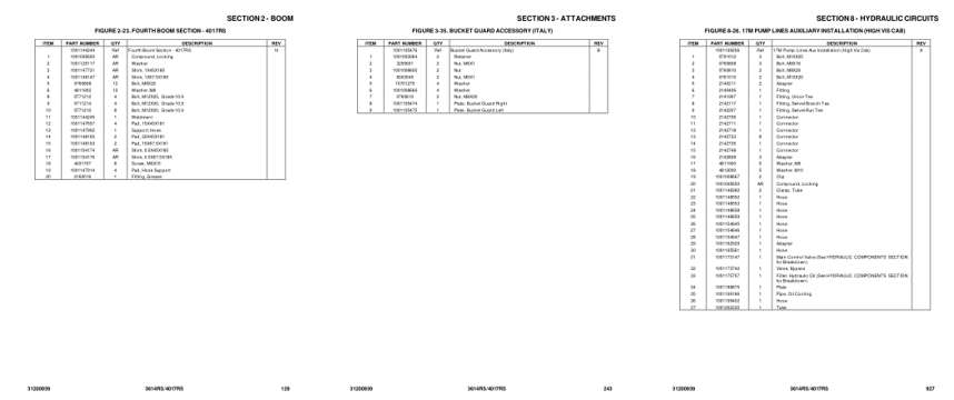
- Parts illustration, page 129: SECTION 2 - BOOM
- Parts illustration, page 243: SECTION 3 - ATTACHMENTS
- Parts illustration, page 927: SECTION 8 - HYDRAULIC CIRCUITS
Other manuals for this machine
Save 10% on 2 manuals, 15% on 3 or more. Other manuals for the 3614RS, 4017RS are listed below. Editions cover different serial number ranges: check the serial coverage and tick only the ones that match your machine.
Added to your cart. View cart
This is a parts manual
Here's how it compares to the other manual types.
Service manual
Factory repair procedures and technical information such as specifications, troubleshooting, and wiring and hydraulic diagrams, for the models and systems the manual covers. See What's inside for its topics.
Operator's manual
Safe operation, controls, maintenance schedules, lubrication points, inspections, and basic checks. Repair procedures are in the service manual.
Parts manual
Illustrated diagrams with factory part numbers for identifying components and ordering parts. Repair procedures are in the service manual.
What it's used for
Factory manual for in-house farm and construction shop use. Straightforward, complete, and easy to follow. It contains the OEM information dealership service departments and parts counters use to diagnose problems, identify components, and perform maintenance or repairs correctly.
Service shops and owner/operators who repair their own equipment
Identifying correct parts and seeing how assemblies come apart and go back together
Keeping equipment running with less downtime
Factory manual, 1,262 pages
Quantity one is the manual described above.
Fast free USA shipping
Ships in 1 business day.
60-day returns
Free if the mistake is ours. A manual ordered in error must come back unopened in its shrink-wrap; you pay return shipping and a 20% restocking fee applies. Return policy
Binder not included
Manuals over about 300 pages may need a standard 3-ring binder, which you can buy locally to keep the pages organized for shop use.
Other editions and similar models
Questions about model, serial number, engine coverage or contents? Contact us before purchasing and we'll help confirm it's the right manual. Please verify the manual type, machine model, serial number range and engine coverage before purchasing: manuals ordered in error carry a 20% restocking fee (return policy).