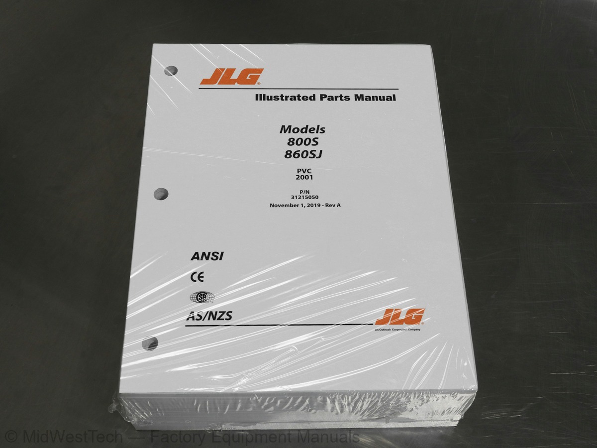
JLG 800S, 860SJ Boom Lift Parts Manual
884 pages · Publication 31215050
Added to your cart. View cart
What's inside
From the manual's own table of contents: 180 sections, 316 entries. See sample pages (PDF, 678 KB)
General52 topics
- SECTION 1 - FRAME
- FIGURE 1-1. AXLE INSTALLATION - FIXED (WITHOUT TOW PACKAGE)
- FIGURE 1-2. AXLE INSTALLATION - OSCILLATING (WITHOUT TOW PACKAGE) (USA BUILT MACHINES)
- FIGURE 1-3. AXLE INSTALLATION - OSCILLATING (WITHOUT TOW PACKAGE) (CHINA BUILT MACHINES)
- FIGURE 1-4. AXLE INSTALLATION - OSCILLATING (WITH TOW PACKAGE) (USA BUILT MACHINES)
- FIGURE 1-5. AXLE INSTALLATION - OSCILLATING (WITH TOW PACKAGE) (CHINA BUILT MACHINES)
- FIGURE 1-6. STEERING INSTALLATION – WITHOUT TOW PACKAGE (USA BUILT MACHINES)
- FIGURE 1-7. STEERING INSTALLATION – WITHOUT TOW PACKAGE (CHINA BUILT MACHINES)
- FIGURE 1-8. STEERING INSTALLATION - WITH TOW PACKAGE (USA BUILT MACHINES)
- FIGURE 1-9. STEERING INSTALLATION - WITH TOW PACKAGE (CHINA BUILT MACHINES)
- FIGURE 1-10. WHEEL DRIVE AND FRAME VALVES INSTALLATION - 2WD
- FIGURE 1-11. WHEEL DRIVE AND FRAME VALVES INSTALLATION – 4WD
- FIGURE 1-12. HUB ASSEMBELY - 2WD FRONT
- FIGURE 1-13. DRIVE HUB/BRAKE ASSEMBLY
- FIGURE 1-14. DRIVE MOTOR ASSEMBLY - 2WD
- FIGURE 1-15. DRIVE MOTOR ASSEMBLY - 4WD
- FIGURE 1-16. TIRE & WHEEL INSTALLATION - 15-625 NHS FOAM-FILLED
- FIGURE 1-17. TIRE AND WHEEL INSTALLATION 18-625 NHS FOAM-FILLED TIRE
- FIGURE 1-18. TIRE AND WHEEL INSTALLATION 18-625 NHS FOAM-FILLED NON-MARKING TIRE
- FIGURE 1-19. LP TANK BRACKETS INSTALLATIONS
- FIGURE 1-20. FRAME SHIELDS INSTALLATION - 2WS
- FIGURE 1-21. TOW PACKAGE INSTALLATION (ENGLISH DECALS)
- FIGURE 1-22. TOW PACKAGE INSTALLATION (FRENCH/ENGLISH DECALS)
- FIGURE 1-23. TOW BAR ASSEMBLY
- SECTION 2 - TURNTABLE
- FIGURE 2-1. CONTROL VALVES INSTALLATION - 800S
- FIGURE 2-2. CONTROL VALVES INSTALLATION - 860SJ
- FIGURE 2-3. MAIN CONTROL VALVE ASSEMBLY
- FIGURE 2-4. SWING DRIVE INSTALLATION
- FIGURE 2-5. SWING MOTOR/HUB ASSEMBLY
- FIGURE 2-6. TURNTABLE BEARING INSTALLATION
- FIGURE 2-7. REMOTE BEARING LUBE INSTALLATION
- FIGURE 2-8. TURNTABLE LOCK INSTALLATION
- FIGURE 2-9. ROTARY COUPLING INSTALLATION
- FIGURE 2-10. TANK INSTALLATION - GAS ENGINES
- FIGURE 2-11. TANK INSTALLATION - DIESEL ENGINES
- FIGURE 2-12. TANK INSTALLATION - DIESEL ENGINES (MACHINES WITH HOSTILE ENVIRONMENT PACKAGE)
- FIGURE 2-13. HYDRAULIC TANK ASSEMBLY
- FIGURE 2-14. AUXILIARY PUMP WITH BATTERY WITHOUT BATTERY DISCONNECT SWITCH INSTALLATION
- FIGURE 2-15. AUXILIARY PUMP WITH BATTERY WITH BATTERY DISCONNECT SWITCH INSTALLATION
- SPECS)
- FIGURE 2-17. GROUND CONTROL BOX ASSEMBLY - 800S WITH DEUTZ D2011 (CE SPECS)
- FIGURE 2-19. GROUND CONTROL BOX ASSEMBLY - 860SJ WITH DEUTZ D2011 (CE SPECS)
- JAPANESE SPECS)
- JAPANESE AND CHINA SPECS)
- EXPORT (HRC) AND CSA SPECS)
- EXPORT (HRC), AUSTRALIAN AND CSA SPECS)
- FIGURE 2-26. LIGHT PANEL INSTALLATION (USA BUILT MACHINES)
- FIGURE 2-27. LIGHT PANEL INSTALLATION (CHINA BUILT MACHINES)
- FIGURE 2-28. ALARM INSTALLATION
- FIGURE 2-29. WHITE NOISE ALARM INSTALLATION
- FIGURE 2-30. STROBE LIGHT INSTALLATION (AMBER)
Show all 181 sections
FIGURE 3-31. FORD ENGINE DRIVE BELT INSTALLATION (MACHINES WITHOUT GENERATOR)55 topics
- FIGURE 3-32. FORD ENGINE COMPONENTS
- FIGURE 3-33. PUMP COUPING KIT (DEUTZ ENGINES)
- FIGURE 3-34. HYDROSTATIC PUMP ASSEMBLY
- FIGURE 3-35. VARIABLE PUMP ASSEMBLY
- FIGURE 3-36. EXHAUST PIPE INSTALLATION - DEUTZ TD2.9L4 AND TD2.9L4 (STAGE V) ENGINES
- FIGURE 3-37. EXHAUST PIPE INSTALLATION - FORD DF 2.5L ENGINES
- FIGURE 3-38. SPARK ARRESTOR MUFFLER INSTALLATION - DEUTZ D2011 ENGINES
- FIGURE 3-39. FUEL-WATER SEPARATOR INSTALLATION - DEUTZ D2011
- FIGURE 3-40. FUEL-WATER SEPARATOR INSTALLATION - DEUTZ TD2.9L4
- FIGURE 3-41. FUEL FILTER ASSEMBLY (DEUTZ TD2.9L4 ENGINES)
- FIGURE 3-43. RIGHT ENGINE SUPPORT INSTALLATION (DEUTZ D2011 ENGINES MACHINES WITH GENERATORS)
- ABS HOODS
- STEEL HOODS
- FIGURE 3-46. ENGINE TRAY JACK INSTALLATION - DEUTZ ENGINES
- FIGURE 3-47. ENGINE TRAY JACK INSTALLATION - FORD ENGINES
- FIGURE 3-48. 2500W/110V/60HZ GENERATOR INSTALLATION - DEUTZ D2011 ENGINES
- FIGURE 3-49. 2500W/110V/60HZ GENERATOR INSTALLATION - DEUTZ TD2.9L4 ENGINES
- FIGURE 3-50. 2500W/110V/60HZ GENERATOR INSTALLATION - FORD ENGINES
- FIGURE 3-51. 2500W/220V/50HZ GENERATOR INSTALLATION - DEUTZ D2011 ENGINES
- FIGURE 3-52. 4000W/50HZ GENERATOR INSTALLATION - DEUTZ D2011 ENGINES
- FIGURE 3-53. 4000W/60HZ GENERATOR INSTALLATION - DEUTZ D2011 ENGINES
- FIGURE 3-54. 4000W/50HZ GENERATOR INSTALLATION - DEUTZ TD2.9L4 ENGINES
- FIGURE 3-55. 4000W/60HZ GENERATOR INSTALLATION - DEUTZ TD2.9L4 ENGINES
- FIGURE 3-56. 7500W/50HZ SKYPOWER GENERATOR INSTALLATION - DEUTZ D2011 ENGINES
- FIGURE 3-57. 7500W/60HZ SKYPOWER GENERATOR INSTALLATION - DEUTZ D2011 ENGINES
- ENGINES
- FIGURE 3-60. 7500W/60HZ SKYPOWER GENERATOR INSTALLATION – FORD DF 2.5L ENGINES
- SECTION 4 - BOOM
- FIGURE 4-1. BOOMS AND CYLINDERS INSTALLATION - 800S
- FIGURE 4-2. BOOMS AND CYLINDERS INSTALLATION - 860SJ (USA BUILT MACHINES)
- FIGURE 4-3. BOOMS AND CYLINDERS INSTALLATION - 860SJ (CHINA BUILT MACHINES)
- FIGURE 4-4. MAIN BOOM ASSEMBLY - 800S
- FIGURE 4-5. MAIN BOOM ASSEMBLY - 860SJ
- FIGURE 4-6. JIB ASSEMBLY (USA BUILT MACHINES)
- FIGURE 4-7. JIB ASSEMBLY (CHINA BUILT MACHINES)
- FIGURE 4-8. ROTATOR ASSEMBLY - 800S
- FIGURE 4-9. ROTATOR ASSEMBLY - 860SJ
- FIGURE 4-10. PLATFORM SUPPORT INSTALLATION
- FIGURE 4-11. POWER TRACK INSTALLATION - MAIN BOOM - 800S
- FIGURE 4-12. POWER TRACK INSTALLATION - MAIN BOOM - 860SJ
- FIGURE 4-13. CONTROL VALVE INSTALLATION - 800S
- FIGURE 4-14. CONTROL VALVE INSTALLATION - 860SJ
- FIGURE 4-15. PLATFORM VALVE ASSEMBLY - 800S
- FIGURE 4-16. PLATFORM VALVE ASSEMBLY - 860SJ
- FIGURE 4-17. LEVEL SENSOR SWITCH INSTALLATION
- SECTION 5 - PLATFORM
- FIGURE 5-1. PLATFORM ASSEMBLY WITH DROP-BAR - 30IN X 3FT (76CM X 1M)
- FIGURE 5-2. PLATFORM ASSEMBLY WITH DROP-BAR - 30IN X 4FT (76CM X 1.22M)
- FIGURE 5-3. PLATFORM ASSEMBLY WITH DROP-BAR - 30IN X 5FT (76CM X 1.52M)
- FIGURE 5-4. PLATFORM ASSEMBLY WITH DROP-BAR - 36IN X 6FT (91.5CM X 1.83M)
- FIGURE 5-5. PLATFORM ASSEMBLY WITH DROP BAR - 36IN X 6FT (91.5CM X 1.83M) (SHIPYARD MACHINES)
- PLATFORM BUMPERS REQIRED)
- FIGURE 5-7. PLATFORM ASSEMBLY WITH DROP-BAR - 36IN X 8FT (91.5CM X 2.44M)
- FIGURE 5-8. PLATFORM ASSEMBLY WITH GATE - 30IN X 4FT (76CM X 1.22M)
- FIGURE 5-9. PLATFORM ASSEMBLY WITH GATE - 30IN X 5FT (76CM X 1.52M) (USA BUILT MACHINES
FIGURE 7-7. HYDRAULIC DIAGRAM - STANDARD (860SJ WITHOUT TWO BAR PACKAGE)24 topics
- FIGURE 7-8. HYDRAULIC DIAGRAM - STANDARD (860SJ WITH TWO BAR PACKAGE)
- SECTION 8 - ELECTRICAL
- FIGURE 8-2. AC BOX AT PLATFORM INSTALLATION - 220V (ANSI, CSA & JAPANESE SPECS)
- (ANSI EXPORT, AUSTRALIAN & CE SPECS)
- FIGURE 8-4. AC BOX AT PLATFORM MID-BOOM PLUG INSTALLATION (WITHOUT GENERATOR) (CHINA SPECS)
- GENERATOR)
- OR NO GENERATOR OPTION)
- FIGURE 8-9. AC BOX AT PLATFORM INSTALLATION - 220V IEC 60309 BLUE WITH 2500W GENERATOR (CE SPECS)
- GENERATOR OR NO GENERATOR OPTION)
- (CE SPECS)
- 2500W GENERATOR OR NO GENERATOR OPTION)
- GENERATOR (CE SPECS)
- 4000W GENERATOR)
- RECEPTACLE) (4000W GENERATOR)
- WITH 4000W SKYPOWER GENERATOR)
- SKYPOWER GENERATOR)
- FIGURE 8-25. ANALYZER CALBE HARNESS
- FIGURE 8-26. BEACON CONTROL HARNESS (BLUE AND RED STROBE LIGHTS)
- FIGURE 8-27. BATERY DISCONNECT SWITCH INSTALLATION
- FIGURE 8-28. BOOM CABLES INSTALLATION - 800S WITHOUT ARCTIC PACKAGE (ALL SPECS)
- ANSI EXPORT, CSA AND JAPANESE SPECS)
- ANSI EXPORT AND CSA SPECS)
- FIGURE 8-33. BOOM CABLES INSTALLATION - 860SJ WITHOUT ARCTIC PACKAGE (ALL SPECS)
- (ANSI, ANSI EXPORT, CSA AND JAPANESE SPECS)
FIGURE 9-21. SKYWELDER DECAL INSTALLATION - 60HZ5 topics
- SECTION 10 - RECOMMENDED SERVICE PARTS STOCK
- FIGURE 10-1. MODEL 800S/860SJ STANDARD PARTS
- SECTION 11 - SPECIAL OPTIONS
- FIGURE 11-1. SPECIAL OPTIONS
- PART NUMBER INDEX
Inside this manual
Real pages from this parts manual (884 pages). Open the sample pages (PDF, 677 KB)

- Parts illustration, page 363: SECTION 3 - ENGINE
- Parts illustration, page 571: SECTION 6 - CYLINDER
- Parts illustration, page 844: SECTION 9 - DECALS
Other manuals for this machine
Save 10% on 2 manuals, 15% on 3 or more. Other manuals for the 800S, 860SJ are listed below. Editions cover different serial number ranges: check the serial coverage and tick only the ones that match your machine.
Added to your cart. View cart
This is a parts manual
Here's how it compares to the other manual types.
Service manual
Factory repair procedures and technical information such as specifications, troubleshooting, and wiring and hydraulic diagrams, for the models and systems the manual covers. See What's inside for its topics.
Operator's manual
Safe operation, controls, maintenance schedules, lubrication points, inspections, and basic checks. Repair procedures are in the service manual.
Parts manual
Illustrated diagrams with factory part numbers for identifying components and ordering parts. Repair procedures are in the service manual.
What it's used for
Factory manual for in-house farm and construction shop use. Straightforward, complete, and easy to follow. It contains the OEM information dealership service departments and parts counters use to diagnose problems, identify components, and perform maintenance or repairs correctly.
Service shops and owner/operators who repair their own equipment
Identifying correct parts and seeing how assemblies come apart and go back together
Keeping equipment running with less downtime
Factory manual, 884 pages
Quantity one is the manual described above.
Fast free USA shipping
Ships in 1 business day.
60-day returns
Free if the mistake is ours. A manual ordered in error must come back unopened in its shrink-wrap; you pay return shipping and a 20% restocking fee applies. Return policy
Binder not included
Manuals over about 300 pages may need a standard 3-ring binder, which you can buy locally to keep the pages organized for shop use.
Other editions and similar models
Questions about model, serial number, engine coverage or contents? Contact us before purchasing and we'll help confirm it's the right manual. Please verify the manual type, machine model, serial number range and engine coverage before purchasing: manuals ordered in error carry a 20% restocking fee (return policy).