MidWestTechService, Parts and Operator's Manuals, in stock and ready to ship!
Fast free USA shippingShips in 1 business daySave 10% on 2 manuals, 15% on 3+

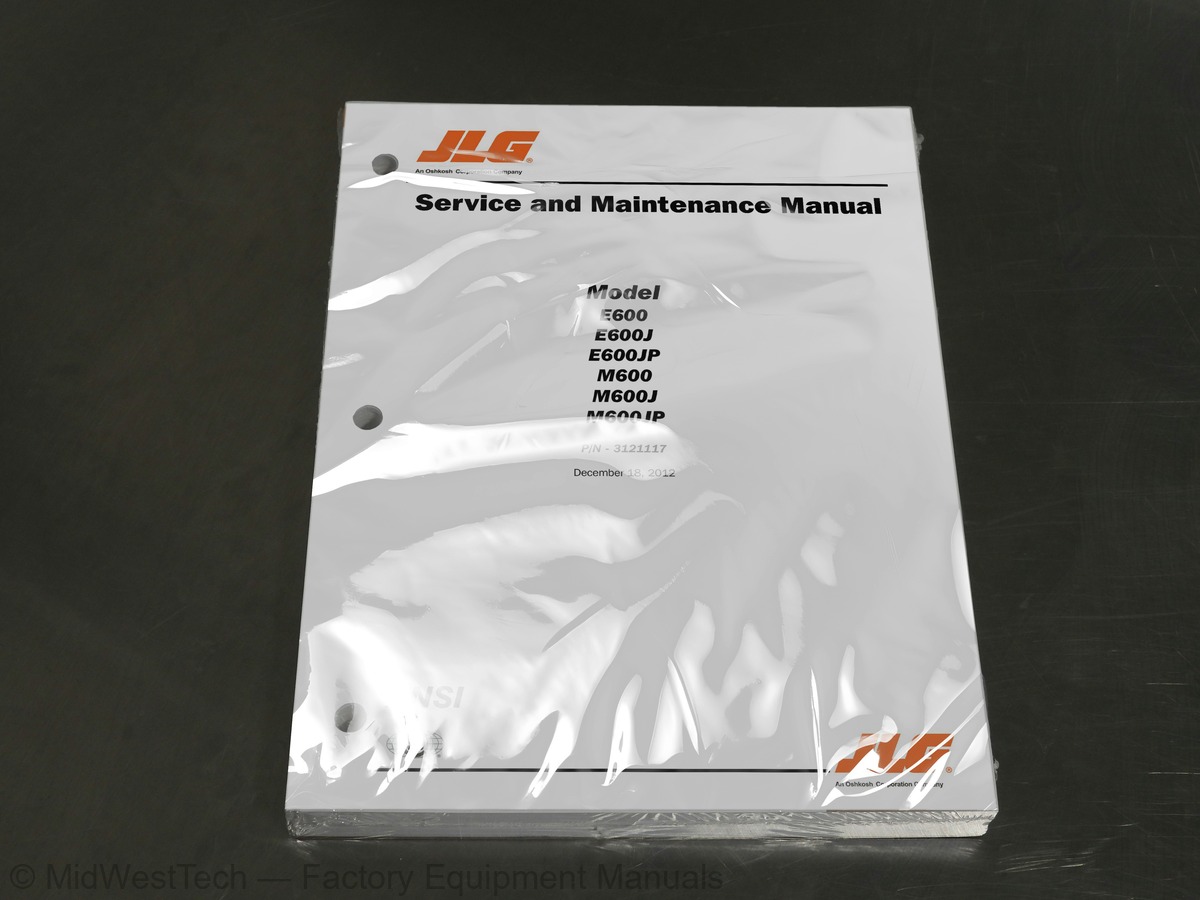
JLG E600, E600J, E600JP, M600, M600J, M600JP Boom Lift Service Manual

222 pages · Publication 3121117

$69.83
Fast free USA shippingShips in 1 business daySave 10% on 2 manuals, 15% on 3 or morePay by credit or debit card or with PayPal. No PayPal account needed.
Models
E600, E600J, E600JP, M600, M600J, M600JP
Serial coverage
Prior to 0300219230, Exclude Serial Number Range: 0300218866, 0300218868
Manual type
Service Manual
Pages
222
Publication
3121117
Condition
Brand new
JLG E600, E600J, E600JP, M600, M600J, M600JP Boom Lift Service Manual, publication 3121117

What's inside

From the manual's own table of contents: 312 sections, 369 entries. See sample pages (PDF, 616 KB)

General
Hydraulic System Safety
Maintenance7 topics
  • Capacities
  • Operating specifications
  • Generator
  • Battery Charger
  • Drive/Steer System
  • Tires
  • Function Speeds
Machine Orientation When Doing Speed Tests
Test Notes7 topics
  • Pressure Settings
  • Torque Requirements
  • Major Component Weights
  • Serial Number Location
  • Hydraulic Oil
  • Operator Maintenance
  • Machine Preparation, Inspection, and Maintenance
Preparation, Inspection, and Maintenance
Pre-Start Inspection
Pre-Delivery Inspection and Frequent Inspection
Annual Machine Inspection
Preventative Maintenance1 topic
  • Service and Guidelines
Safety and Workmanship
Cleanliness
Components Removal and Installation
Component Disassembly and Reassembly
Pressure-Fit Parts
Bearings
Gaskets
Bolt Usage and Torque Application
Hydraulic Lines and Electrical Wiring
Hydraulic System
Lubrication
Battery
Lubrication and Servicing1 topic
  • Lubrication and Information
Hydraulic Oil
Show all 312 sections
Changing Hydraulic Oil
Lubrication Specifications1 topic
  • SECTION NO. TITLE PAGE NO. Cylinder Drift Test
Platform Drift
Cylinder Drift2 topics
  • Pins and Composite Bearing Repair Guidelines
  • Welding on JLG Equipment
Do the Following When Welding on JLG Equipment
Do NOT Do the Following When Welding on JLG Equipment2 topics
  • Applying Silicone Dielectric Compound to Electrical Connections
  • Tires & Wheels
Tire Inflation
Tire Damage
Tire Replacement
Wheel Replacement
Wheel Installation
Disengaging for Towing
Engaging after Towing is Complete
Disassembly
Disassembly of Cover
Disassembly of the first stage planetary assembly (7)
Disassembly of second stage planet gears (1)
Assembly of first stage planetary assembly (7)
Assembly of end cover unit (8)
Final Assembly
Initial Start-Up and After Repairs
Oil Change Interval-Gear Drive1 topic
  • Drive Hub (S/N 115723 to Present)
Roll and Leak Testing
Tightening and Torquing Bolts
Main Disassembly
Output Carrier Disassembly
Input Carrier Disassembly
Hub-Spindle Disassembly
Cover Disassembly
Input Carrier Assembly
Output Planet Gear Assembly
Output Carrier Assembly
Hub-Spindle Assembly
Cover Subassembly
Main Assembly1 topic
  • Drive Brake - Mico
Assembly
Bleeding1 topic
  • Speed Sensor Adjustment
Adjustment Procedure
Speed Sensor Installation Verification
Verification w/ Analyzer Procedure2 topics
  • Oscillating Axle Lockout Test (If Equipped)
  • Oscillation Cylinder Bleeding
Bleeding Procedure
Checking Oscillation Cylinders1 topic
  • SECTION NO. TITLE PAGE NO. Swing Drive
Roll, Leak and Brake Testing
Motor Control Valve Disassembly
Motor and Brake Disassembly
Hub-shaft Disassembly
Carrier Disassembly
Hub-Shaft Sub-Assembly
Carrier Sub-Assembly
Motor-Brake Subassembly
Motor-Brake Assembly
Motor Control Valve Assembly
Tube Fitting Assembly Procedures
Procedure for Setting Gear Backlash1 topic
  • Swing Bearing
Turntable Bearing Mounting Bolt Condition Check
Wear Tolerance
Replacement of Swing Bearing
Swing Bearing Torque Value
Swing Drive Installation
Setting Backlash1 topic
  • Battery Maintenance and Charging
Battery Maintenance, Quarterly
Optional On Board Generator
Battery Charging (On Board Charger)
Removing the Battery Box1 topic
  • Generator (Prior to S/N 88375)
Timing Sequences
To Connect the JLG Control System Analyzer to the Generator
Alarms and Fault Flash Codes
Output Current and Voltage Settings
Priming the Fuel Line1 topic
  • Generator (S/N 88375 to Present)
Engine
Alternator
Dynamo and Dynamo Voltage Regulator
Dynamo Output Fuse
Control Fuse
Start Battery
Engine Starter
Start Control Relay
Fuel Control Relay
Glow Plug Control Relay
Glow Plug
Fuel Pump
Fuel Solenoid
Engine Low Oil Pressure Switch
Engine Oil Temperature Sensor
Alternator Output Current Sensor
Engine Speed Sensor
RBS Engine/Generator Controller
SECTION NO. TITLE PAGE NO. Warnings and Safety Precautions
System Controls
System Status and Performance Monitoring
System Settings
RBS Start
RBS shutdown
RBS Alarms and Flash Codes
Resetting the RBS Controller
Maintenance Schedule
Troubleshooting
APU Engine Start Battery Boosting1 topic
  • Supplementary fuse for Engine Generator Controller
Tools And Material
Procedure1 topic
  • Boom
Removal
Installation2 topics
  • Load Cell Calibration Procedure
  • Platform Rotator (Prior to S/N 0300130810)
Theory of Operation
Disassembly and Inspection
Assembly and Testing1 topic
  • Platform Rotator (S/N 0300130810 to Present)
Required Tools
Inspection1 topic
  • Jib Rotator
Operating Principle
Reassembly
Installing Counterbalance Valve
Testing the Actuator
Installation and Bleeding1 topic
  • Lubricating O-Rings in the Hydraulic System
Cup and Brush
Dip Method
Spray Method
Brush-on Method1 topic
  • Cylinders - Theory of Operation
Lift, Telescope, Slave, Master, Oscillation (if equipped), Jib (if equipped), and Steer1 topic
  • Cylinder Checking Procedures
Cylinder Without Counterbalance Valves
Cylinders With Single Counterbalance Valve
Cylinders With Dual Counterbalance Valve1 topic
  • SECTION NO. TITLE PAGE NO. Cylinder Repair
Cleaning and Inspection
Proportional Main Relief
Lift Down
Lift Up
Swing
Flow Control / Bang Bang Main Relief
Steer
Platform Level Down
Platform Level Up Relief
Jib Relief9 topics
  • Introduction
  • To Connect the JLG Control System Analyzer
  • Using the Analyzer
  • Changing the Access Level of the Hand Held Analyzer
  • Adjusting Parameters Using the Hand Held Analyzer
  • Machine Setup
  • Machine Personality Settings
  • Machine Configuration Programming Information
  • Level Vehicle Description
Help Descriptions and Fault Flash Codes4 topics
  • Analyzer Diagnostics Menu Structure
  • System Self Test
  • General
  • Multimeter Basics
Grounding
Backprobing
Min/Max
Polarity
Scale
Voltage Measurement
Resistance Measurement
Continuity Measurement
Current Measurement1 topic
  • Checking Switches
Basic Check
Limit Switches
Automatic Switches
Switch Wiring - Low Side, High Side1 topic
  • AMP Connector
Applying Silicone Dielectric Compound to AMP Connectors
Wedge Lock
Service - Voltage Reading1 topic
  • Deutsch Connectors
DT/DTP Series Assembly
DT/DTP Series Disassembly
HD30/HDP20 Series Assembly
HD30/HDP20 Series Disassembly
Serial Number Location
Operator Maintenance and Lubrication Diagram
Torque Chart (SAE Fasteners - Sheet 1 of 7)
Torque Chart (SAE Fasteners - Sheet 2 of 7)
Torque Chart (SAE Fasteners - Sheet 3 of 7)
Torque Chart (SAE Fasteners - Sheet 4 of 7)
Torque Chart (METRIC Fasteners - Sheet 5 of 7)
Torque Chart (METRIC Fasteners - Sheet 6 of 7)
Torque Chart (METRIC Fasteners - Sheet 7 of 7)
Operating Temperature Specifications - Kubota
Torque Hub
Main Disassembly Drawing 1
Main Disassembly Drawing 2
Output Carrier
Planet Gear
Input Carrier
Hub Spindle
Cover Assembly
Hub Assembly - Sheet 1 of 2
Cup Pressing Tool
Drive Brake
Speed Sensor Orientation
Drive Components
Oscillating Axle
Axle Oscillation Lockout Valve
Brake Disassembly
Hub Shaft Disassembly
Setting Gear Backlash
Swing Bearing Feeler Gauge Check
Swing Bearing Tolerance Measuring Point
Swing Drive and Bearing Installation
Swing Bearing Torque Sequence
Battery Cable Routing
Batteries and Battery Charger
Battery Charger
Battery Charger Schematic
Generator Components
Generator System Analyzer Flow Chart
Generator
Boom Assembly - Sheet 1 of 3
Boom Assembly - Sheet 2 of 3
Boom Assembly - Sheet 3 of 3
Boom Limit Switch Adjustment
Transport Limit Switch (CE Only)
Platform Support Torque Values
Load Sensor
Timing Marks
Platform Rotator Assembly - Cutaway
Rotary Actuator - Exploded View
Rotary Actuator - Assembly Drawing
Operating Principle - Jib Rotator
Jib Rotator Assembly
Tool for Removing End Cap
Rotator Counterbalance Valve
Cylinder Barrel Support
Capscrew Removal
Axle Lockout Cylinder
Level Cylinder
Jib Lift Cylinder
Lift Cylinder
Master Cylinder
Steer Cylinder
Telescope Cylinder
Cylinder Rod Support
Tapered Bushing Removal
Gar-Max Bearing Installation
Rod Seal Installation
Wiper Seal Installation
Installation of Head Seal Kit
Piston Seal Kit Installation
Tapered Bushing Installation
Seating the Tapered Bearing
Poly-Pak Piston Seal Installation
Rod Assembly Installation
Hydraulic Tank and Pump (Prior to S/N 51941)
Hydraulic Tank and Pump (S/N 51941 to Present)
Hydraulic Control Valve - Main Valve
Hydraulic Control Valve - Platform Valve
Hand Held Analyzer
Analyzer Flow Chart - Sheet 1 of 2
Analyzer Flow Chart - Sheet 2 of 2
Control Module Location
Voltage Measurement (DC)
Current Measurement (DC)
Connector Assembly Figure 1
AMP Connector
Connector Assembly Figure 2
Connector Assembly Figure 3
Connector Assembly Figure 4
Connector Disassembly
Connector Installation
DT/DTP Contact Installation
DT/DTP Contact Removal
HD/HDP Contact Installation
HD/HDP Locking Contacts Into Position
HD/HDP Contact Removal
HD/HDP Unlocking Contacts
Electrical Components Installation - Sheet 1
Electrical Components Installation - Sheet 2
Electrical Schematic - Sheet 1 of 4
Electrical Schematic - Sheet 2 of 4
Electrical Schematic - Sheet 3 of 4
Electrical Schematic - Sheet 4 of 4
Hydraulic Schematic - Sheet 1 of 2
Hydraulic Schematic - Sheet 2 of 2
Capacities
Operating Specifications
Drive System
Tires
Function Speeds
Pressure Settings
Torque Requirements
Component Weights
Mobil DTE 11M Specs
Mobil DTE 13M Specs
Mobil EAL H 46 Specs
Inspection and Maintenance
Inspection and Preventive Maintenance Schedule
Wheel Torque Chart
Drive Brake Diagnosis
RBS Prestart Sequence
RBS Startup Sequence
RBS Shutdown Sequence
Generator System Flash Codes
Controller Interface Pin Assignments
Cylinder Head and Tapered Bushing Torque Specifications
Holding Valve Torque Specifications
Machine Setup Descriptions
Personality Ranges/Defaults
Machine Configuration Programming Information
JLG Control System Flash Codes
ADJUSTMENTS - Personality Descriptions
Diagnostic Menu Descriptions
Calibration Descriptions
Calibration Ranges/Defaults
System Test Descriptions
System Test Messages

Inside this manual

Real pages from this service manual (222 pages). Open the sample pages (PDF, 615 KB)
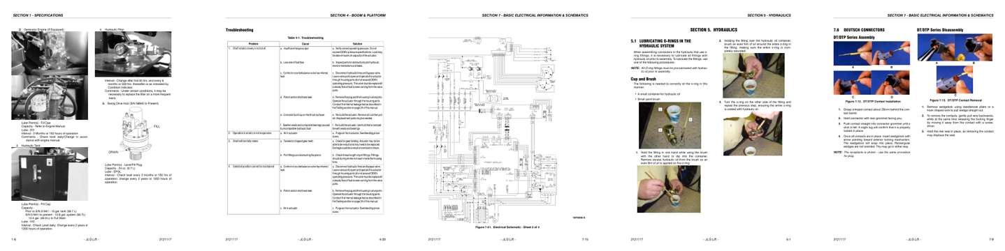
Sample pages from the JLG E600, E600J, E600JP, M600, M600J, M600JP Boom Lift Service Manual: Specifications, Troubleshooting, Diagram, Color page, Color page
  • Specifications, page 20: SECTION 1 - SPECIFICATIONS
  • Troubleshooting, page 143: SECTION 4 - BOOM & PLATFORM
  • Diagram, page 215: SECTION 7 - BASIC ELECTRICAL INFORMATION & SCHEMATICS
  • Color page, page 145: SECTION 5 - HYDRAULICS
  • Color page, page 209: SECTION 7 - BASIC ELECTRICAL INFORMATION & SCHEMATICS

Other manuals for this machine

Save 10% on 2 manuals, 15% on 3 or more. Other manuals for the E600, E600J, E600JP, M600, M600J, M600JP are listed below. Editions cover different serial number ranges: check the serial coverage and tick only the ones that match your machine.

This manual: Service Manual 3121117$69.83
Other manuals for the E600, E600J, E600JP, M600, M600J, M600JP

Parts manuals

Details
Details
Details

This is a service manual

Here's how it compares to the other manual types.

This manual

Service manual

Factory repair procedures and technical information such as specifications, troubleshooting, and wiring and hydraulic diagrams, for the models and systems the manual covers. See What's inside for its topics.

Operator's manual

Safe operation, controls, maintenance schedules, lubrication points, inspections, and basic checks. Repair procedures are in the service manual.

Parts manual

Illustrated diagrams with factory part numbers for identifying components and ordering parts. Repair procedures are in the service manual.

Engine service manuals are sometimes sold separately, since certain machine models were offered with more than one engine option.

What it's used for

Factory manual for in-house farm and construction shop use. Straightforward, complete, and easy to follow. It contains the OEM information dealership service departments and parts counters use to diagnose problems, identify components, and perform maintenance or repairs correctly.

Service shops and owner/operators who repair their own equipment

Identifying correct parts and seeing how assemblies come apart and go back together

Keeping equipment running with less downtime

Factory manual, 222 pages

Quantity one is the manual described above.

Fast free USA shipping

Ships in 1 business day.

60-day returns

Free if the mistake is ours. A manual ordered in error must come back unopened in its shrink-wrap; you pay return shipping and a 20% restocking fee applies. Return policy

Other editions and similar models

Questions about model, serial number, engine coverage or contents? Contact us before purchasing and we'll help confirm it's the right manual. Please verify the manual type, machine model, serial number range and engine coverage before purchasing: manuals ordered in error carry a 20% restocking fee (return policy).