MidWestTechService, Parts and Operator's Manuals, in stock and ready to ship!
Fast free USA shippingShips in 1 business daySave 10% on 2 manuals, 15% on 3+

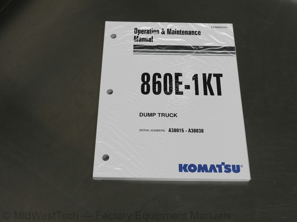
Komatsu 860E-1KT Dump Truck Operation & Maintenance Manual

189 pages · Publication CEAM022401

$69.65
Fast free USA shippingShips in 1 business daySave 10% on 2 manuals, 15% on 3 or morePay by credit or debit card or with PayPal. No PayPal account needed.
Models
860E-1KT
Serial coverage
A30015 - A30030
Manual type
Operation & Maintenance Manual
Pages
189
Publication
CEAM022401
Condition
Brand new
Komatsu 860E-1KT Dump Truck Operation & Maintenance Manual, publication CEAM022401

What's inside

From the manual's own table of contents: 296 sections, 317 entries. See sample pages (PDF, 548 KB)

General1 topic
  • TABLE OF CONTENTS INTRODUCTION
FOREWARD
TRUCK MODEL ILLUSTRATION
ABOUT THIS MANUAL
ALERTS PAGE
STANDARD CHARTS AND TABLES
SAFETY
GENERAL
Safety Rules
Safety Features
Fire Extinguisher And First Aid Kit
Clothing And Personal Items
Leaving The Operator’s Seat
Mounting And Dismounting
Fire Prevention For Fuel And Oil
Precautions With High Temperature Fluids
Asbestos Dust Hazard Prevention
Prevention Of Injury By Work Equipment
Unauthorized Modification
ROPS Precautions
Precautions For Attachments
Precautions For Starting The Truck
PRECAUTIONS BEFORE OPERATION
Safety At The Worksite
Show all 297 sections
Fire Prevention
Preparing For Operation
Ventilation In Enclosed Areas
In Operator’s Cab - Before Starting The Engine
Mirrors, Windows And Lights
OPERATING THE TRUCK
When Starting The Engine
General Truck Operation
Traveling In Reverse
Traveling
Traveling On Slopes
Ensuring Good Visibility
Operating On Snow Or Ice
Avoiding Damage To Dump Body
Driving Near High Voltage Cables1 topic
  • TABLE OF CONTENTS (cont.) When Dumping
Working On Loose Ground
When Loading
Parking The Truck
TOWING
WORKING NEAR BATTERIES
Battery Hazard Prevention
Jump Starting With Booster Cables
Jump Starting With Receptacles
BEFORE PERFORMING MAINTENANCE
Warning Tag
Stopping The Engine Before Service
Proper Tools
Securing The Dump Body
WHILE PERFORMING MAINTENANCE
Keep The Truck Clean
Attachments
Working Under The Truck
Rotating Fan And Belts
Adding Fuel Or Oil
Radiator Coolant Level
Use Of Lighting
Precautions With The Battery
Handling High Pressure Hoses
Precautions When Performing Maintenance Near High Temperature Or High Pressure
Precautions With High Pressure Oil
Waste Materials
TIRES
Handling Tires
Tire Maintenance
Storing Tires After Removal
WHEN REPAIRS ARE NECESSARY
SPECIAL PRECAUTIONS FOR WORKING ON AC DRIVE TRUCKS
Engine Shutdown Procedure Before Welding or Performing Maintenance
Precautions Before Welding or Performing Maintenance
ADDITIONAL JOB SITE RULES
WARNINGS AND CAUTIONS1 topic
  • TABLE OF CONTENTS (cont.) OPERATING INSTRUCTIONS
WALK AROUND INSPECTION
ENGINE START-UP
AFTER ENGINE HAS STARTED
MACHINE OPERATION SAFETY PRECAUTIONS
OPERATING ON THE HAUL ROAD
STARTING ON A GRADE WITH A LOADED TRUCK
PASSING
LOADING
DUMPING
Raising The Dump Body
Lowering The Dump Body (When dumping on flat ground)
Lowering The Dump Body (When dumping over a berm or into a crusher)
Operating in trolley line mode
Getting on line
Operating on trolley
Getting off line
Line status signals
Trolley disconnect
Traffic consideration for trolley line operation
Approaching slow moving vehicles in a trolley assisted truck
Operating slow moving vehicles on trolley assist ramps
Truck failure while on trolley
USING THE SPEED CONTROL FEATURE
SAFE PARKING PROCEDURES
NORMAL ENGINE SHUTDOWN PROCEDURE
SUDDEN LOSS OF ENGINE POWER
FUEL DEPLETION
Special Wiring Harness
Towing Procedure
DISABLED TRUCK OPERATION
STEERING AND BRAKE SYSTEM
Components Required
Hookup
DISABLED TRUCK DUMPING PROCEDURE
Raising the Body
Lowering the Body
RESERVE ENGINE OIL SYSTEM1 topic
  • TABLE OF CONTENTS (cont.) OPERATOR CAB AND CONTROLS
STEERING WHEEL AND CONTROLS
Horn Button
Tilt / Telescope Lever
Speed Control Lever
Multi-Function Turn Signal Switch
DYNAMIC RETARDING
Dynamic Retarder/Service Brake Pedal
Throttle/Accelerator Pedal
GRADE/SPEED RETARD CHART
OVERHEAD PANEL COMPONENTS
CENTER CONSOLE
Directional Control Lever
Override/Fault Reset Switch
Engine Shutdown Switch
L.H. Window Control Switch R.H. Window Control Switch
Hoist Control Lever
Ashtray
Lighter
Data Store Button
Service Engine Light
12V Auxiliary Power Outlets
DIAGNOSTIC PORTS
Drive System #1
Engine (QUANTUM)
Drive System #3
Engine (CENSE)
Interface Module
VHMS
Payload Meter
OPERATOR’S SEAT
Seat Belts
Adjustment
PASSENGER SEAT (STANDARD SEAT)
HEATER/AIR CONDITIONER COMPARTMENT AND CONTROLS
Fan Speed Control Knob
Temperature Control Knob
Air Flow Directional Knob
Heater/Air Conditioner Vents
INSTRUMENT PANEL
Control Symbols
Key Switch1 topic
  • TABLE OF CONTENTS (cont.) Speed Control Switch
Traction Control Switch
Retarding Grid Drier Switch
AC Drive System Rest Switch
Wheel Brake Lock Switch
Pantograph Switch
Hazard Warning Lights
Fuel Level Gauge
Hydraulic Oil Temperature Gauge
Speedometer/Digital Display
Coolant Temperature Gauge
Drive System Temperature Gauge
Headlight/Panel Illumination Light Switch
Ladder Light Switch (3-Way)
Backup Light Switch
Fog Light Switch
Mode Switches
Panel Illumination Light Dimmer Switch
Right/Left Turn Signal Indicators
Digital Display Contrast Buttons
Warning Light
STATUS INDICATOR LIGHTS
Body Up
Parking Brake Applied
Propulsion System Not Ready
No Propel
Engine Warming Up
Engine Delay
Grid Drier
Wheel Brake Lock Applied
Traction Control
Repair Monitor
Snapshot
Pantograph Energized
Pantograph Up
Service Brake Applied
No DC Link Voltage
DIGITAL DISPLAY OPERATION
Toggling Through Main Level Screens
Toggling Through Warning Screens
Entering Payload Meter Data1 topic
  • TABLE OF CONTENTS (cont.) REAR AXL LIGHT BAR
Backup Lights
Retard Lights
Brake Light
Backup Alarm
KOMTRAX PLUS
Operation
Basic Precautions
FUSES AND CIRCUIT BREAKERS
LUBRICATION AND SERVICE
860E-1K SERVICE CAPACITIES
HYDRAULIC TANK SERVICE
Adding Oil
COOLING SYSTEM SERVICE
Radiator Filling Procedure
Coolant Specifications
Unacceptable Practices
Reserve Oil Tank Filling Procedure (Remote fill)
Inline Screen
QUICK FILL SERVICE CENTER
LUBRICATION CHART
HOUR (DAILY) INSPECTIONS
INITIAL 50 HOUR LUBRICATION AND MAINTENANCE CHECKS
INITIAL 100 HOUR LUBRICATION AND MAINTENANCE CHECKS
HOUR LUBRICATION AND MAINTENANCE CHECKS
1,000 HOURS LUBRICATION AND MAINTENANCE CHECKS
2,000 HOUR MAINTENANCE CHECKS
3,000 HOUR MAINTENANCE CHECKS
5,000 HOUR MAINTENANCE CHECKS
6,000 HOUR MAINTENANCE CHECKS
AUTOMATIC LUBRICATION SYSTEM
GENERAL DESCRIPTION
SYSTEM COMPONENTS
Filter Assembly
Hydraulic Motor and Pump
Grease Reservoir
Pressure Reducing Valve
Flow Control Valve
Solenoid Valve
Vent Valve1 topic
  • TABLE OF CONTENTS (cont.) Grease System Failure Switch
Injectors
Unloader Valve
SYSTEM OPERATION
GENERAL INSTRUCTIONS
Required Lubricant
System Priming
LUBRICANT PUMP
Pump Housing Oil Level
Pump Pressure Control
INJECTORS (SL-1 Series “H”)
Injector Specifications
Injector Adjustment
INJECTOR OPERATION
PREVENTIVE MAINTENANCE PROCEDURES
Daily Lubrication System Inspection
Hour Inspection
SYSTEM CHECKOUT
Lubrication Cycle Operation
SYSTEM TROUBLESHOOTING CHART
COMPONENTS & SPECIFICATIONS
MAJOR COMPONENTS DESCRIPTIONS
SPECIFICATIONS
PAYLOAD METER III
RADIO/CD PLAYER
OPERATING INSTRUCTIONS
GENERAL RADIO RECEIVER FUNCTIONS
Turning On the Power
One-Hour Timer
Adjusting the Volume
Display
Radio Mode Displays
CD Mode Displays
MP3/USB/iPod Mode Displays
AUX Input Displays
CLOCK/ALARM Button
Front Auxiliary Mode1 topic
  • TABLE OF CONTENTS (cont.) Rear Auxiliary Mode
Adjusting the Receiver Audio Settings
Adjusting the Receiver Menu Settings
USING THE RADIO
Finding a Station
Setting the Presets
USING THE CLOCK
Setting the Clock
USING THE ALARM
Setting the Alarm
Turning the Alarm Off
Activating Snooze
USING THE WEATHERBAND (USA Only)
USING THE COMPACT DISC PLAYER/USB
Playing A Compact Disc
Button Functions
PLAYING AN MP3 DISC/USB
Root Directory
Empty Directory or Folder
No Folder
File Name Display
PLAYING MP3 FILES
USING AN iPOD®
Playing an iPod
OPERATING TIPS
Tips About The Audio System
Understanding Radio Reception
Care of The Compact Discs
TROUBLESHOOTING
TABLE13 topics
  • TABLE 1 Standard Tightening Torque For Metric Cap screws and Nuts
  • TABLE 2 Standard Tightening Torque For SAE Grade 5 & 8 Cap Screws and Nuts
  • TABLE 3 Standard Tightening Torque 12-Pt, Grade 9, Cap Screws (SAE)
  • TABLE 4 Tightening Torque for T-Bolt Type Hose Clamps
  • TABLE 5 Standard Tightening Torque For Split Flange Clamp Bolts
  • TABLE 6 Tightening Torque For Flared Tube And Hose Fittings
  • TABLE 7 JIC 37° Swivel Nuts Torque Chart (SAE)
  • TABLE 8 Pipe Thread Torque Chart (SAE)
  • TABLE 9 O-Ring Boss Torque Chart (SAE)
  • TABLE 10 O-Ring Face Seal Torque Chart (SAE)
  • TABLE 11 Common Conversions Multipliers - Metric -to- English
  • TABLE 12 Common Conversions Multipliers - English -to- Metric
  • TABLE 13 Temperature Conversions

Inside this manual

Real pages from this operation & maintenance manual (189 pages). Open the sample pages (PDF, 546 KB)
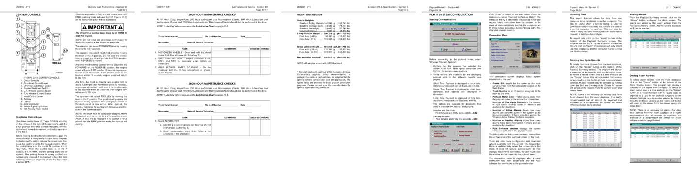
Sample pages from the Komatsu 860E-1KT Dump Truck Operation & Maintenance Manual: Controls and operation, Maintenance, Specifications, Color page, Color page
  • Controls and operation, page 88: Operator Cab And Controls - Section 32
  • Maintenance, page 130: Lubrication and Service - Section 40
  • Specifications, page 148: Components & Specifications - Section 5
  • Color page, page 163: Payload Meter III - Section 60
  • Color page, page 173: Payload Meter III - Section 60

Other manuals for this machine

Save 10% on 2 manuals, 15% on 3 or more. Other manuals for the 860E-1KT are listed below. Editions cover different serial number ranges: check the serial coverage and tick only the ones that match your machine.

This manual: Operation & Maintenance Manual CEAM022401$69.65
Other manuals for the 860E-1KT

Service manuals

Details
Details
Details

This is an operator's manual

Here's how it compares to the other manual types.

Service manual

Factory repair procedures and technical information such as specifications, troubleshooting, and wiring and hydraulic diagrams, for the models and systems the manual covers. See What's inside for its topics.

This manual

Operator's manual

Safe operation, controls, maintenance schedules, lubrication points, inspections, and basic checks. Repair procedures are in the service manual.

Parts manual

Illustrated diagrams with factory part numbers for identifying components and ordering parts. Repair procedures are in the service manual.

What it's used for

Factory manual for in-house farm and construction shop use. Straightforward, complete, and easy to follow. It contains the OEM information dealership service departments and parts counters use to diagnose problems, identify components, and perform maintenance or repairs correctly.

Service shops and owner/operators who repair their own equipment

Identifying correct parts and seeing how assemblies come apart and go back together

Keeping equipment running with less downtime

Factory manual, 189 pages

Quantity one is the manual described above.

Fast free USA shipping

Ships in 1 business day.

60-day returns

Free if the mistake is ours. A manual ordered in error must come back unopened in its shrink-wrap; you pay return shipping and a 20% restocking fee applies. Return policy

Other editions and similar models

Questions about model, serial number, engine coverage or contents? Contact us before purchasing and we'll help confirm it's the right manual. Please verify the manual type, machine model, serial number range and engine coverage before purchasing: manuals ordered in error carry a 20% restocking fee (return policy).