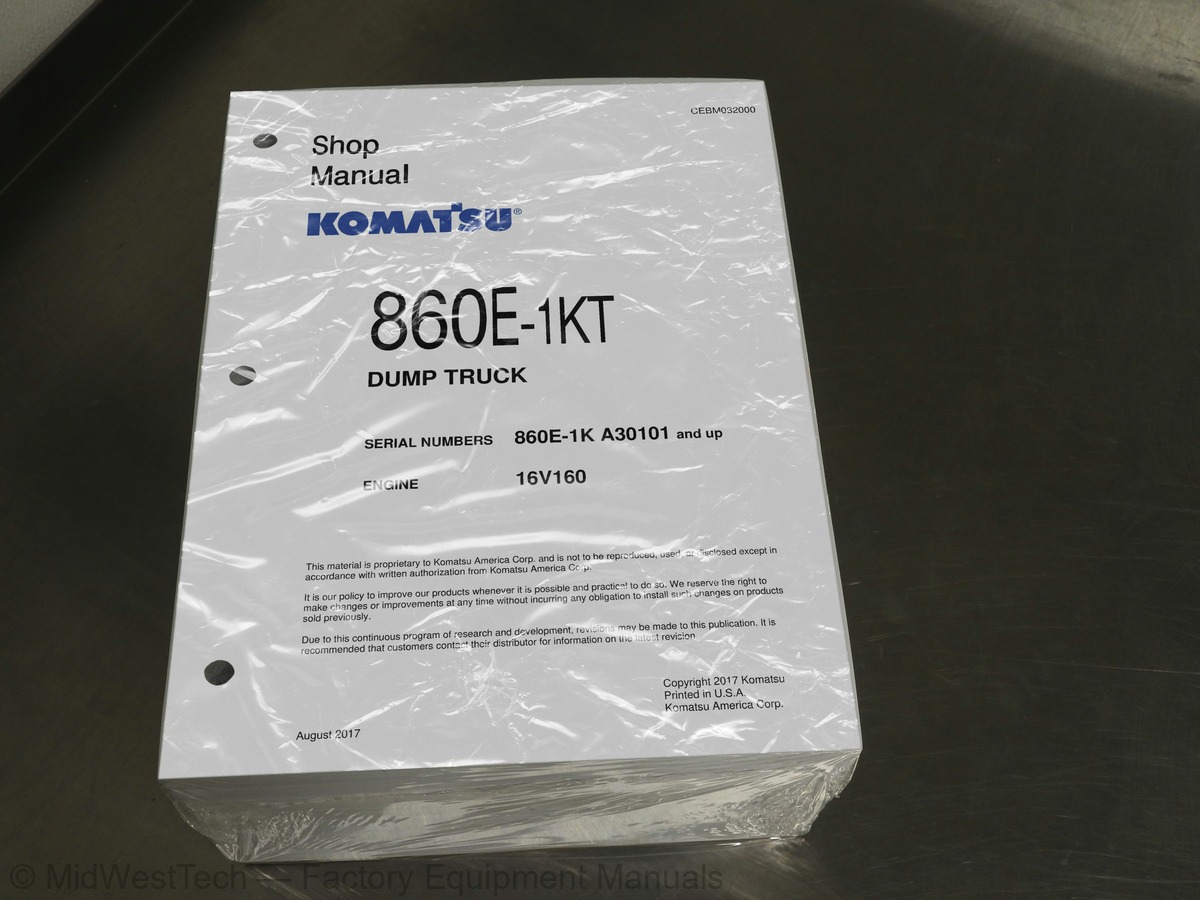
Komatsu 860E-1KT with 16V160 Engine Dump Truck Service Manual
1,951 pages · Publication CEBM032000
Added to your cart. View cart
- Models
- 860E-1KT with 16V160 Engine
- Serial coverage
- A30101 and up
- Manual type
- Service Manual
- Pages
- 1,951
- Publication
- CEBM032000
- Condition
- Brand new
What's inside
From the manual's own table of contents: 361 sections, 700 entries. See sample pages (PDF, 1180 KB)
Show all 361 sections
Disabled truck operation26 topics
- Specification drawing
- Specifications
- Weight table
- Fuel, coolant and lubricants
- General information
- Principles of refrigeration
- Air conditioning system components
- Air conditioning system electrical circuit
- Steering circuit operation
- Steering circuit components
- Flow amplifier operation
- Steering/brake pump operation
- Steering cylinder wear data
- Hoist circuit operation
- Hoist circuit components
- Hoist pilot valve operation
- Hoist cylinder wear data
- Service brake circuit operation
- Secondary braking and auto apply
- Rear wheel brake lock circuit operation
- Parking brake circuit operation
- Brake lines and test ports
- Brake warning circuit operation
- Brake assembly wear data
- Front suspension wear data
- Rear suspension wear data
Ground tie capacitor42 topics
- Low-inductance bus bar assembly
- Free-wheeling diode for low-inductance bus bars
- Contactor (grid box and main blower motor)
- Contactor (control power)
- Contactor (DC contactors)
- Contactor (crowbar bypass)
- Temperature probes (PT100 style)
- Coolant inlet temperature sensor
- Coolant outlet temperature sensor (external pad style)
- IGBT module heat sink temperature sensor
- Coolant outlet temperature sensor (internal style)
- Circuit breakers
- Inner circulating blower fan
- Coolant pump
- Motor for coolant pump
- Coolant pressure sensor
- Inner radiator
- Ground voltage monitoring resistors
- Protection thyristor assembly (crowbar)
- Discharge reactor
- Main blower motor
- Grid box
- Grid box blower motor
- Grid box blower motor grease fittings
- Main alternator
- Main alternator circuit diagram
- IGBT – inverter/chopper phase module
- Troubleshooting information
- Main input rectifier module
- Internal circuit diagram
- Upper ground tie resistor
- Lower ground tie resistor
- Troubleshooting
- Speed sensor, alternator
- Speed sensors, wheel motors
- Traction motor
- SIBAS ® 32 Traction Control Unit (TCU)
- Overview of the SIBAS ® 32 systems
- Removing and installing the SIBAS ® 32 cards
- SIBAS ® 32 card device names
- Structure of SIBAS ® 32 card part number
- SIBAS ® 32 card interchangeability
Recovering and recycling refrigerant30 topics
- Evacuating the air conditioning system
- Charging the air conditioning system
- General information on system checkout
- Steering system checkout procedures
- Steering system checkout data sheet
- Toe-in adjustment
- Brake cooling and hoist system checkout procedures
- Brake cooling and hoist system checkout data sheet
- Hydraulic system flushing procedure
- Front suspension pressure test
- Rear suspension pressure test
- Steering cylinder leakage test
- Hoist cylinder leakage test
- Brake circuit checkout procedure
- Brake system checkout data sheet
- Brake piston leakage test
- Wet disc brake bleeding procedure
- Parking brake bleeding procedure
- Brake valve bench test and adjustment
- Accumulator charging and storage
- Accumulator leak testing
- Suspension oiling and charging procedures
- Suspension pressure test
- Payload meter initial setting procedure
- KOMTRAX Plus and payload meter software
- KOMTRAX Plus controller initial setting procedure
- KOMTRAX Plus initialization check list
- Precautions for replacing KOMTRAX Plus initialization form
- KOMTRAX Plus controller
- KOMTRAX Plus controller checkout procedure
Operat.Data37 topics
- Energy Usage data
- Mileage indicator
- Operating cycles
- Service Brake on data
- Temperature data
- Motor torque data
- Engine speed data
- Gear test
- Acc test
- Engine_Test
- X_Test_Inx
- STate intern
- ST inverter status
- Vehicle status
- Pedal calib
- Language
- OFFline-test
- Variables
- IV:Vehic-ID
- Commands
- Settings
- Parameters
- Temp_prot
- Appendix
- Background commands
- Monitor commands for the central processing unit
- Monitor commands for the signal processing unit
- Monitor Program – Loading software into the SIBAS
- Loading software into the DSP procedure
- Loading a DSP program Inverter A
- Loading a DSP program Inverter B
- Loading software into the CPU procedure
- Loading ZR software Prog. jumpers Reset
- Setting the system up After loading a new pgm
- Loading the proper pgm file
- Body position switches (with proximity switches and metal arms)
- Body position switches (with proximity switches and magnets)
Fault Code A153: Battery voltage is low with the truck in operation35 topics
- Fault Code A154: Battery charging voltage is excessive
- Fault Code A155: Battery charging voltage is low
- readings
- Fault Code A166: Left rear hydraulic oil temperature sensor is low
- Fault Code A167: Right rear hydraulic oil temperature sensor is low
- Fault Code A168: Left front hydraulic oil temperature sensor is low
- Fault Code A169: Right front hydraulic oil temperature sensor is low
- Fault Code A170: Left rear hydraulic oil temperature sensor is high
- Fault Code A171: Right rear hydraulic oil temperature sensor is high
- Fault Code A172: Left front hydraulic oil temperature sensor is high
- Fault Code A173: Right front hydraulic oil temperature sensor is high
- Fault Code A182: (A30003 only) The battery 12 Volt battery tap has high voltage
- Fault Code A183: (A30003 only) The battery 12 Volt battery tap has low voltage
- Fault Code A184: J1939 data link is not connected
- Fault Code A194: Left front hydraulic oil temperature is high
- Fault Code A195: Right front hydraulic oil temperature is high
- Fault Code A196: Left rear hydraulic oil temperature is high
- Fault Code A197: Right rear hydraulic oil temperature is high
- Fault Code A198: Hoist pressure 1 sensor is high
- Fault Code A199: Hoist pressure 2 sensor is high
- Fault Code A200: Steering pressure sensor is high
- Fault Code A201: Brake pressure sensor is high
- Fault Code A202: Hoist pressure 1 sensor is low
- Fault Code A203: Hoist pressure 2 sensor is low
- Fault Code A204: Steering pressure sensor is low
- Fault Code A205: Brake pressure sensor is low
- Fault Code A206: Ambient temperature sensor is high
- Fault Code A207: Ambient temperature sensor is low
- having applied
- having released
- Fault Code A215: Brake auto apply valve circuit is defective
- brake command valve circuit
- been attempted
- Fault Code A230: Parking brake has been requested while truck still moving
- Fault Code A231: The body is up while traveling or with selector in forward or neutral
Fault Code A278: Service brake applied while loading37 topics
- Fault Code A279: Low Steering Pressure Switch bad
- Fault Code A280: Steering accumulator bled switch bad
- Fault Code A281: Brake lock degrade switch bad
- without the engine running has reached 7
- parking brake was not set
- secondary shutdown switch was operated
- was turned off
- delay relay circuit
- after the latched keyswitch circuit is off
- Fault Code A295: The right front park brake is not setting up
- Fault Code A296: The left front park brake is not setting up
- Fault Code A297:The right rear park brake is not setting up
- Fault Code A298: The left rear park brake is not setting up
- Fault Code A299: The right front park brake is not releasing
- Fault Code A300: The left front park brake is not releasing
- Fault Code A301: The right rear park brake is not releasing
- Fault Code A302: The left rear park brake is not releasing
- Fault Code A303: Shifter is defective
- Fault Code A304: (A30004 & Up) Auto lube grease level fault
- Fault Code A305: (A30004 & Up) Auto lube circuit is defective
- Fault Code A309: No brakes applied when expected
- Fault Code A310: Low fuel warning
- Fault Code A311: Brake lock switch is on when it should not be
- low readings
- high readings
- Fault Code A314: (A30004 & Up) DCDC converter 12 volt circuit is high
- Fault Code A315: (A30004 & Up) DCDC converter 12 volt circuit is low
- Fault Code A316: Starter engagement has been attempted with engine running
- Fault Code A317: Operation of brake auto apply valve without a detected response
- Fault Code A318: Unexpected power loss to Interface Module
- Fault Code A328: Drive system not powered up
- Fault Code A350: Overload on output 1B
- Fault Code A351: Overload on output 1E
- Fault Code A352: (A30003) Overload on output 1H
- Fault Code A352: (A30004 & Up) Overload on output 1H
- Fault Code A353: Overload on output 1J
- Fault Code A354: Overload on output 1K
L1B SYS: Regular inhibit fault active44 topics
- L1A SYS: GW Test stopped by A/D converter faulty
- L3C DSP A: Initialization fault detected by DSP
- L3C DSP A: SW-WatchdoG
- L3C DSP A: Initialization fault detected by CPU
- L1B DSP A: SW-Traco triggered
- L1B DSP A: SW-Traco full
- L3C DSP A: Time slice overflow T1
- L3C DSP A: Time slice overflow T2
- L3C DSP A: Time slice overflow T3
- L3C DSP A: Time slice overflow T4
- L1A DSP A: Communication HSCX data from DSP B missing
- L1A DSP A: Communication HSCX data from DSP T missing
- L3C DSP A: Current offset during pulse block
- L3C DSP A: Current offset during no pulse block
- L3A DSP A: Overcurrent fault
- L3C DSP A: Current transducer defective phase U
- L3C DSP A: Current transducer defective phase W
- L1A DSP A: Modulation software fault
- L3A DSP A: Active current controller at limit
- L3A DSP A: Active current reference at limit
- L1A DSP A: Braking chopper controller at limit
- L3C DSP A: Phase unbalance too large
- L3A DSP A: Pulse block by DSP software
- L3C DSP A: U/F Card defective
- L3C DSP A: Difference in current of phase U overlimit
- L3C DSP A: Difference in current of phase W over limit
- L3C DSP B: Initialization fault detected by DSP
- L3C DSP B: SW-Watchdog
- L3C DSP B: Initialization fault detected by CPU
- L1B DSP B: SW-Traco triggered
- L1B DSP B: SW-Traco full
- L3C DSP B: Time slice overflow T1
- L3C DSP B: Time slice overflow T2
- L3C DSP B: Time slice overflow T3
- L3C DSP B: Time slice overflow T4
- L1A DSP B: Communication HSCX data from DSP A missing
- L1A DSP B: Communication HSCX data from DSP T missing
- L3C DSP B: Current offset during pulse block
- L3C DSP B: Current offset during no pulse block
- L3A DSP B: Overcurrent fault
- L3C DSP B: Current transducer defective phase V
- L3C DSP B: Current transducer defective phase W
- L1A DSP B: Modulation software fault
- L3A DSP B: Active current controller at limit
L3C IO: CPU Watchdog triggered44 topics
- L3C IO: DSP A Watchdog triggereD
- L3C IO: DSP B Watchdog triggered
- L3C IO: CPU Reset triggered
- L1B IO: CPU Traco triggered
- L3A IO: Pulse block from I/O
- L3A IO: DC link voltage A level 1 exceeded
- L3A IO: DC link voltage B level 1 exceeded
- L3C IO: Trolley line overvoltage
- L3B IO: Trolley line overcurrent
- L2B IO: Trolley line current transducer faulty
- L2B IO: Trolley line voltage transducer faulty
- L3A IO: Throttle pedal out of range
- L3A IO: Retard pedal out of range
- L1A IO: Cruise speed control module out of range
- L3C UWSA1: Supervision bus clock
- L3C UWSA1: Supervision module clock
- L3C UWSA1: Incorrect FPGA version identifier
- L3C UWSA1: Incorrect FPGA project identifier
- L3C UWSA1: GW Comparator faulty during start-up test
- L1A UWSA1: ADC Faulty
- L3C UWSA1: Configuration failure
- L1A UWSA1: Hardware failure counter / processor
- L3A UWSA1: Peak current protection active
- L3D UWSA1: Peak current protection pulse start
- L3D UWSA1: Number of peak current protection >limit
- L3D UWSA1: Supervision switching frequency
- L1A UWSA1: Overvoltage level 1 exceeded
- L3D UWSA1: Limit 5 overcurrent phase U
- L3D UWSA1: Limit 5 overcurrent phase V
- L3D UWSA1: Limit 5 overcurrent phase W
- L3D UWSA1: Limit 5 overvoltage DC bus
- L3D UWSA1: Checkback INVA1 L1U faulty
- L3D UWSA1: Checkback INVA1 L1L faulty
- L3D UWSA1: Checkback INVA1 L2U faulty
- L3D UWSA1: Checkback INVA1 L2L faulty
- L3D UWSA1: Checkback INVA1 L3U faulty
- L3D UWSA1: Checkback INVA1 L3L faulty
- L3D UWSA1: Checkback chopper A faulty
- L3C UWSB1: Supervision bus clock
- L3C UWSB1: Supervision module clock
- L3C UWSB1: Incorrect FPGA version identifier
- L3C UWSB1: Incorrect FPGA project identifier
- L3C UWSB1: GW Comparator faulty during start-up test
- L1A UWSB1: ADC Faulty
L3C UWSB2: Incorrect FPGA project identifier44 topics
- L3C UWSB2: GW Comparator faulty during start-up test
- L1A UWSB2: ADC Faulty
- L3C UWSB2: Configuration failure
- L1A UWSB2: Hardware failure counter / processor
- L3A UWSB2: Peak current protection active
- L3D UWSB2: Peak current protection pulse start
- L3D UWSB2: Number of peak current protection >limit
- L3D UWSB2: Supervision switching frequency
- L1A UWSB2: Overvoltage level 1 exceeded
- L3D UWSB2: Limit 5 overcurrent phase V1
- L3D UWSB2: Limit 5 overcurrent phase U1
- L3D UWSB2: Limit 5 overcurrent phase W1
- L3D UWSB2: Limit 5 overvoltage DC bus
- L3D UWSB2: Checkback INVB2 L1U Faulty
- L3D UWSB2: Checkback INVB2 L1L Faulty
- L3D UWSB2: Checkback INVB2 L2U Faulty
- L3D UWSB2: Checkback INVB2 L2L Faulty
- L3D UWSB2: Checkback INVB2 L3U Faulty
- L3D UWSB2: Checkback INVB2 L3L Faulty
- L3D UWSB2: Checkback chopper D Faulty
- L3C UWSST: Supervision bus clock
- L3C UWSST: Supervision module clock
- L3C UWSST: Incorrect FPGA version identifier
- L3C UWSST: Incorrect FPGA project identifieR
- L3C UWSST: GW Comparator faulty during start-up test
- L1A UWSST: ADC Faulty
- L3C UWSST: Configuration failure
- L1A UWSST: Hardware failure counter / processor
- L3A UWSST: Peak current protection active
- L3D UWSST: Number of peak current protection >limit
- L3D UWSST: Supervision switching frequency
- L3C UWSST: Crowbar is fired without command
- L3D UWSST: Limit 5 overcurrent phase U
- L3D UWSST: Limit 5 overcurrent phase V
- L3D UWSST: Limit 5 overcurrent phase W
- L3D UWSST: Limit 5 overvoltage DC bus
- L3D UWSST: Checkback INVST L1U Faulty
- L3D UWSST: Checkback INVST L1L Faulty
- L3D UWSST: Checkback INVST L2U Faulty
- L3D UWSST: Checkback INVST L2L Faulty
- L3D UWSST: Checkback INVST L3U Faulty
- L3D UWSST: Checkback INVST L3L Faulty
- L3C UWSST: Checkback crowbar faulty
- L1A BUS: CAN Communication failure
Inside this manual
Real pages from this service manual (1,951 pages). Open the sample pages (PDF, 1178 KB)

- Specifications, page 411: 30 Testing and adjusting
- Troubleshooting, page 801: Operator Action
- Diagram, page 1,881: XS6731-1 SEPT 08
- Color page, page 1,793: 50 Disassembly and assembly
- Color page, page 479: 30 Testing and adjusting
- Foldout diagram, page 1,888: Auxilliary control cabinet
This is a service manual
Here's how it compares to the other manual types.
Service manual
Factory repair procedures and technical information such as specifications, troubleshooting, and wiring and hydraulic diagrams, for the models and systems the manual covers. See What's inside for its topics.
Operator's manual
Safe operation, controls, maintenance schedules, lubrication points, inspections, and basic checks. Repair procedures are in the service manual.
Parts manual
Illustrated diagrams with factory part numbers for identifying components and ordering parts. Repair procedures are in the service manual.
Engine service manuals are sometimes sold separately, since certain machine models were offered with more than one engine option.
What it's used for
Factory manual for in-house farm and construction shop use. Straightforward, complete, and easy to follow. It contains the OEM information dealership service departments and parts counters use to diagnose problems, identify components, and perform maintenance or repairs correctly.
Service shops and owner/operators who repair their own equipment
Identifying correct parts and seeing how assemblies come apart and go back together
Keeping equipment running with less downtime
Factory manual, 1,951 pages
Quantity one is the manual described above.
Fast free USA shipping
Ships in 1 business day.
60-day returns
Free if the mistake is ours. A manual ordered in error must come back unopened in its shrink-wrap; you pay return shipping and a 20% restocking fee applies. Return policy
Binder not included
Manuals over about 300 pages may need a standard 3-ring binder, which you can buy locally to keep the pages organized for shop use.
Other editions and similar models
Questions about model, serial number, engine coverage or contents? Contact us before purchasing and we'll help confirm it's the right manual. Please verify the manual type, machine model, serial number range and engine coverage before purchasing: manuals ordered in error carry a 20% restocking fee (return policy).