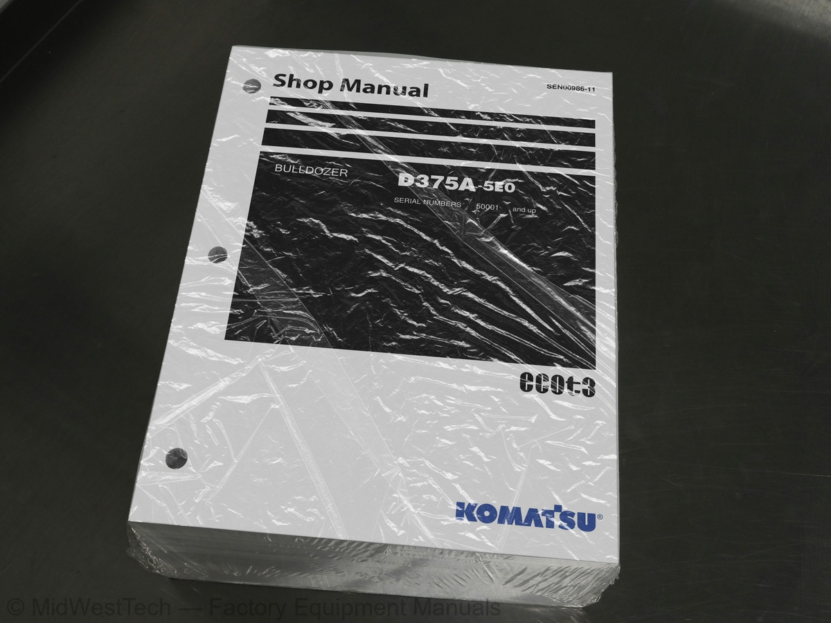
Komatsu D375A-5E0 Bulldozer Service Manual
1,619 pages · Publication SEN00986-11
Added to your cart. View cart
- Models
- D375A-5E0
- Serial coverage
- 50001 and up
- Manual type
- Service Manual
- Pages
- 1,619
- Publication
- SEN00986-11
- Condition
- Brand new
What's inside
From the manual's own table of contents: 274 sections, 568 entries. See sample pages (PDF, 821 KB)
Show all 274 sections
Track frame43 topics
- Recoil spring
- Idler
- Track roller
- Carrier roller
- Track roller bogie
- Track shoe
- Main frame
- Suspension
- Work equipment hydraulic piping diagram
- PPC control piping diagram
- Work equipment control
- Hydraulic tank
- Accumulator
- PPC lock valve
- PPC valve
- Hydraulic cylinder
- Piston valve
- Quick drop valve
- Pin puller switch
- Pin puller solenoid valve
- Blade control knob (Only the machine with dual tilt)
- Pitch, dual tilt solenoid valve
- Work equipment pump
- Control valve
- Self pressure reducing valve
- Cylinder stay
- Blade
- Cutting edge, end bit
- Ripper
- Cab mount
- Air conditioner
- Engine control system
- CRI engine control system
- Monitor system
- Machine monitor
- Mode selection system
- Electrical equipment
- Palm command control system
- Sensors
- Vehicle health monitoring system (VHMS)
- ORBCOMM terminal system
- Standard value table for engine
- Standard value table for machine
Initialization procedures for VHMS controller36 topics
- Using method of KOMTRAX functions of ORBCOMM terminal
- Precautions for replacing VHMS controller
- Pm Clinic service
- Failure codes table
- Fuse locations
- Points to remember when troubleshooting
- Sequence of events in troubleshooting
- Check before troubleshooting
- Classification and procedures for troubleshooting
- Information in troubleshooting table
- Connection table for connector pin numbers
- T-branch box and T-branch adapter table
- Failure code [1380MW] Lockup clutch slip
- Failure code [1500L0] Transmission clutch dual engagement
- Failure code [15E0MW] Transmission clutch slip
- fill signal is ON
- fill signal is OFF
- fill signal is ON
- fill signal is OFF
- fill signal is ON
- fill signal is OFF
- fill signal is ON
- fill signal is OFF
- fill signal is ON
- fill signal is OFF
- Failure code [1800MW] Power train clutch slip
- fill signal is ON
- fill signal is OFF
- fill signal is ON
- fill signal is OFF
- Failure code [2300NR] Brake thermal load abnormality
- fill signal is ON
- fill signal is OFF
- Failure code [2301NR] Right steering brake thermal load abnormality
- fill signal is ON
- fill signal is OFF
Failure code [CA442] Power supply voltage abnormally high level50 topics
- Failure code [CA449] Common rail pressure abnormally high pressure 2
- Failure code [CA451] Common rail pressure sensor abnormally high level
- Failure code [CA452] Common rail pressure sensor abnormally low level
- Failure code [CA553] Common rail pressure abnormally high pressure 1
- Failure code [CA554] Common rail pressure sensor in-range abnormality
- Failure code [CA559] Supply pump low pressure 1
- Failure code [CA689] Engine Ne speed sensor abnormality
- Failure code [CA731] Engine Bkup speed sensor phase abnormality
- Failure code [CA757] Engine controller all data loss
- Failure code [CA778] Engine Bkup speed sensor abnormality
- Failure code [CA1228] EGR valve servo abnormality 1
- Failure code [CA1625] EGR valve servo abnormality 2
- Failure code [CA1633] CAN communication error (Engine controller)
- Failure code [CA2185] Throttle sensor power supply abnormally high level
- Failure code [CA2186] Throttle sensor power supply abnormally low level
- Failure code [CA2249] Supply pump low pressure 2
- Failure code [CA2271] EGR valve lift sensor abnormally high level
- Failure code [CA2272] EGR valve lift sensor abnormally low level
- Failure code [CA2351] EGR valve solenoid drive short circuit
- Failure code [CA2352] EGR valve solenoid drive disconnection
- Failure code [D110KA] Battery relay hold line disconnection
- Failure code [D110KB] Battery relay hold line short circuit
- Failure code [D130KA] Neutral safety relay disconnection
- Failure code [D130KB] Neutral safety relay short circuit
- Failure code [D161KA] Backup alarm relay disconnection
- Failure code [D161KB] Backup alarm relay short circuit
- Failure code [D182KZ] Preheater relay disconnection or short circuit
- Failure code [D190KA] Engine controller ACC signal cut relay disconnection
- Failure code [D190KB] Engine controller ACC signal cut relay short circuit
- Failure code [D5ZRKA] Snap shot switch disconnection
- Failure code [D5ZRKB] Snap shot switch short circuit
- Failure code [DAFRKR] Machine monitor CAN communication error
- Failure code [DAQ0KT] Transmission controller internal abnormality
- Failure code [DAQ1KK] Transmission controller main power supply voltage reduction
- Failure code [DAQ2KK] Transmission controller load power supply voltage reduction
- voltage reduction
- Failure code [DAQ6KK] Transmission controller sensor 24V power supply voltage reduction
- voltage reduction
- Failure code [DAQ9KQ] Transmission controller model selection signal disagreement
- Failure code [DAQRKR] Transmission controller CAN communication error
- Failure code [DAQSKR] Transmission controller S-NET communication error
- Failure code [DB2RKR] Engine controller CAN communication error
- Failure code [DB30KT] Steering controller internal abnormality
- Failure code [DB31KK] Steering controller main power supply voltage reduction
- Failure code [DB32KK] Steering controller load power supply voltage reduction
- Failure code [DB35KK] Steering controller sensor 5V power supply (1) voltage reduction
- Failure code [DB36KK] Steering controller sensor 24V power supply voltage reduction
- Failure code [DB37KK] Steering controller sensor 5V power supply (2) voltage reduction
- Failure code [DB39KQ] Steering controller model selection signal disagreement
- Failure code [dB3RKR] Steering controller CAN communication error
Failure code [DBB0KK] (or VHMS LED display "n901") VHMS supply voltage abnormality4 topics
- abnormality
- power supply voltage reduction
- disconnection or short circuit
- (VHMS controller)
Failure code [DGT1KX] Power train oil temperature sensor input signal out of range55 topics
- system short circuit
- system disconnection
- Failure code [DH22KA] Work equipment pump oil pressure sensor 1 disconnection
- Failure code [DH22KB] Work equipment pump oil pressure sensor 1 short circuit
- Failure code [DH23KA] Work equipment pump oil pressure sensor 2 disconnection
- Failure code [DH23KB] Work equipment pump oil pressure sensor 2 short circuit
- system disconnection
- system short circuit
- input signal out of range
- Failure code [DK10KA] Fuel control dial disconnection
- Failure code [DK10KB] Fuel control dial short circuit
- Failure code [DK30KA] Steering potentiometer 1 disconnection
- Failure code [DK30KB] Steering potentiometer 1 short circuit
- Failure code [DK30KX] Steering potentiometer 1 input signal out of range
- Failure code [DK30KZ] Steering potentiometer 1 disconnection or short circuit
- Failure code [DK30L8] Steering potentiometer 1 analog signal disagreement
- Failure code [DK31KA] Steering potentiometer 2 disconnection
- Failure code [DK31KB] Steering potentiometer 2 short circuit
- Failure code [DK40KA] Brake potentiometer disconnection
- Failure code [DK40KB] Brake potentiometer short circuit
- Failure code [DK55KX] Direction potentiometer input signal out of range
- Failure code [DK55KZ] Direction potentiometer disconnection or short circuit
- Failure code [DK55L8] Direction potentiometer analog signal disagreement
- Failure code [DK56KA] Direction potentiometer 1 disconnection
- Failure code [DK56KB] Direction potentiometer 1 short circuit
- Failure code [DK57KA] Direction potentiometer 2 disconnection
- Failure code [DK57KB] Direction potentiometer 2 short circuit
- Failure code [DK60KA] Acceleration sensor disconnection
- Failure code [DK60KB] Acceleration sensor short circuit
- Failure code [DKH1KA] Pitch angle sensor disconnection
- Failure code [DKH1KB] Pitch angle sensor short circuit
- Failure code [DKH1KX] Pitch angle sensor input signal out of range
- Failure code [DLF1KA] Torque converter output speed sensor disconnection
- Failure code [DLT3KA] Transmission output speed sensor disconnection 1
- Failure code [dLT3KA] Transmission output speed sensor disconnection 2
- Failure code [DLT3KB] Transmission output speed sensor short circuit
- Failure code [DV00KB] Alarm buzzer short circuit
- Failure code [DW59KA] Blade dual selector solenoid disconnection
- Failure code [DW59KB] Blade dual selector solenoid short circuit
- Failure code [DW59KY] Blade dual selector solenoid hot short
- Failure code [DW5AKA] Blade pitch selector solenoid disconnection
- Failure code [DW5AKB] Blade pitch selector solenoid short circuit
- Failure code [DW5AKY] Blade pitch selector solenoid hot short
- Failure code [DW7BKA] Fan reverse solenoid disconnection
- Failure code [DW7BKB] Fan reverse solenoid short circuit
- Failure code [DW7BKY] Fan reverse solenoid hot short
- Failure code [DWN3KA] Sudden stop prevention solenoid disconnection
- Failure code [DWN3KB] Sudden stop prevention solenoid short circuit
- Failure code [DWN3KY] Sudden stop prevention solenoid hot short
- Failure code [DWN5KA] Fan pulley solenoid 1 disconnection
- Failure code [DWN5KB] Fan pulley solenoid 1 short circuit
- Failure code [DWN5KY] Fan pulley solenoid 1 hot short
- Failure code [DWNCKA] Fan pulley solenoid 2 disconnection
- Failure code [DWNCKB] Fan pulley solenoid 2 short circuit
- Failure code [DWNCKY] Fan pulley solenoid 2 hot short
Failure code [DXHCKY] Left brake ECMV hot short3 topics
- abnormally high level
- abnormally high level (2)
- abnormally high level (1)
When the starting switch is ON, none of the machine monitor come on1 topic
- and does not go out
While the preheater is operating, the preheating pilot lamp does not come on2 topics
- (Dual tilt-mounted machine)
- does not come on
Indication of the power train (torque converter) temperature gauge is abnormal53 topics
- The hydraulic oil temperature gauge does not indicate normally
- Indication of the fuel gauge is abnormal
- Indications of gear speed and engine speed are abnormal
- Indication of the shift mode service meter is abnormal
- The switch module cannot be operated
- The warning lamp does not flash or does not go out
- The alarm buzzer does not sound or does not stop
- Auto shift down is not possible or is not released
- The alarm buzzer cannot be cancelled
- The operator mode cannot be operated
- The service mode cannot be operated
- The back-up alarm does not sound
- come on
- Air conditioner does not operate
- Orbcomm terminal does not operate normally (Data are not transmitted)
- Fan does not reverse
- Gear cannot be shifted
- Electric priming pump does not operate or does not stop automatically
- No force (no drawbar pull)
- No travel (at 2nd or 3rd speed)
- No travel at all gear speeds
- Machine travels only in one direction forward or in reverse
- Large time lag at gear speed shifting or forward-reverse shifting
- Steering is not possible
- Steering is possible only on one side
- Steering overrun occurs
- Brake does not work
- Torque converter is not lock-up
- Power train oil overheats
- All work equipment operates slowly
- All work equipment does not operate
- Blade lift speed is slow or lacks power
- Blade tilt speed is slow or lacks power
- Ripper lift speed is slow or lacks power
- Ripper tilt speed is slow or lacks power
- Excessive hydraulic drift of blade lift
- Excessive hydraulic drift of blade tilt
- Excessive hydraulic drift of ripper lift
- Ripper pin puller cylinder does not work (giant ripper attachment machine)
- Blade pitch does not work (dual tilt attachment machine)
- Abnormal sound comes out from around work equipment pump
- engine over heats)
- Method of using troubleshooting chart
- Engine does not start easily
- Engine does not start
- Engine does not pick up smoothly (follow-up is poor)
- Engine stops during operation
- Engine does not rotate smoothly (hunting)
- Engine lacks output (or lacks power)
- Exhaust smoke is black (Incomplete combustion)
- Oil is consumed much (or exhaust gas color is blue)
- Engine oil becomes contaminated quickly
- Fuel consumption is excessive
Removal and installation of bogie assembly47 topics
- Disassembly and assembly of bogie assembly
- Removal and installation of 1st bogie assembly
- Expansion and installation of track shoe assembly
- Whole disassembly and assembly of track shoe
- Dimensions table of fitting jig of link press
- Disassembly and assembly of 1 link in the field
- Disassembly and assembly of master link
- Removal and installation of pivot shaft assembly
- Removal and installation of equalizer bar
- Disassembly and assembly of equalizer bar bushing
- Removal and installation of segment tooth
- Removal and installation of hydraulic tank and control valve assembly
- Removal and installation of work equipment pump assembly
- Removal and installation of fan pump assembly
- Removal and installation of control valve assembly
- Assembly of control valve assembly
- Disassembly and assembly of PPC charge valve assembly
- Disassembly and assembly of blade PPC valve assembly
- Disassembly and assembly of ripper PPC valve assembly
- Disassembly and assembly of hydraulic cylinder assembly
- Disassembly and assembly of ripper pin puller cylinder assembly
- Removal and installation of blade assembly
- Disassembly and assembly of blade assembly
- Disassembly and assembly of giant ripper assembly
- Removal and installation of ROPS guard
- Removal and installation of operator's cab assembly
- Removal and installation of floor frame assembly
- Removal and installation of transmission and steering controller assembly
- Removal and installation of engine controller assembly
- Removal and installation of VHMS controller assembly
- Removal and installation of air conditioner unit assembly
- Removal and installation of monitor panel assembly
- Hydraulic circuit diagram (1/2)
- Hydraulic circuit diagram (2/2)
- Power train hydraulic circuit diagram
- Electrical circuit diagram (1/13)
- Electrical circuit diagram (2/13)
- Electrical circuit diagram (3/13)
- Electrical circuit diagram (4/13)
- Electrical circuit diagram (5/13)
- Electrical circuit diagram (6/13)
- Electrical circuit diagram (7/13)
- Electrical circuit diagram (8/13)
- Electrical circuit diagram (9/13)
- Electrical circuit diagram (10/13)
- Electrical circuit diagram (11/13)
- Electrical circuit diagram (12/13)
Inside this manual
Real pages from this service manual (1,619 pages). Open the sample pages (PDF, 820 KB)
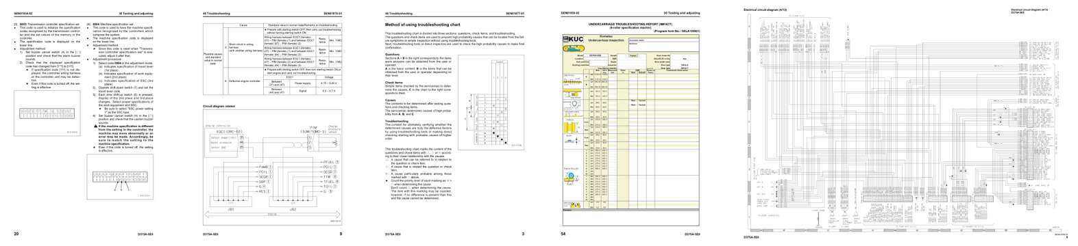
- Specifications, page 492: 30 Testing and adjusting
- Diagram, page 717: Circuit diagram related
- Troubleshooting, page 1,242: Method of using troubleshooting chart
- Color page, page 578: 30 Testing and adjusting
- Foldout diagram, page 1,604: Electrical circuit diagram (4/13)
Other manuals for this machine
Save 10% on 2 manuals, 15% on 3 or more. Other manuals for the D375A-5E0 are listed below. Editions cover different serial number ranges: check the serial coverage and tick only the ones that match your machine.
Added to your cart. View cart
This is a service manual
Here's how it compares to the other manual types.
Service manual
Factory repair procedures and technical information such as specifications, troubleshooting, and wiring and hydraulic diagrams, for the models and systems the manual covers. See What's inside for its topics.
Operator's manual
Safe operation, controls, maintenance schedules, lubrication points, inspections, and basic checks. Repair procedures are in the service manual.
Parts manual
Illustrated diagrams with factory part numbers for identifying components and ordering parts. Repair procedures are in the service manual.
Engine service manuals are sometimes sold separately, since certain machine models were offered with more than one engine option.
What it's used for
Factory manual for in-house farm and construction shop use. Straightforward, complete, and easy to follow. It contains the OEM information dealership service departments and parts counters use to diagnose problems, identify components, and perform maintenance or repairs correctly.
Service shops and owner/operators who repair their own equipment
Identifying correct parts and seeing how assemblies come apart and go back together
Keeping equipment running with less downtime
Factory manual, 1,619 pages
Quantity one is the manual described above.
Fast free USA shipping
Ships in 1 business day.
60-day returns
Free if the mistake is ours. A manual ordered in error must come back unopened in its shrink-wrap; you pay return shipping and a 20% restocking fee applies. Return policy
Binder not included
Manuals over about 300 pages may need a standard 3-ring binder, which you can buy locally to keep the pages organized for shop use.
Other editions and similar models
Questions about model, serial number, engine coverage or contents? Contact us before purchasing and we'll help confirm it's the right manual. Please verify the manual type, machine model, serial number range and engine coverage before purchasing: manuals ordered in error carry a 20% restocking fee (return policy).