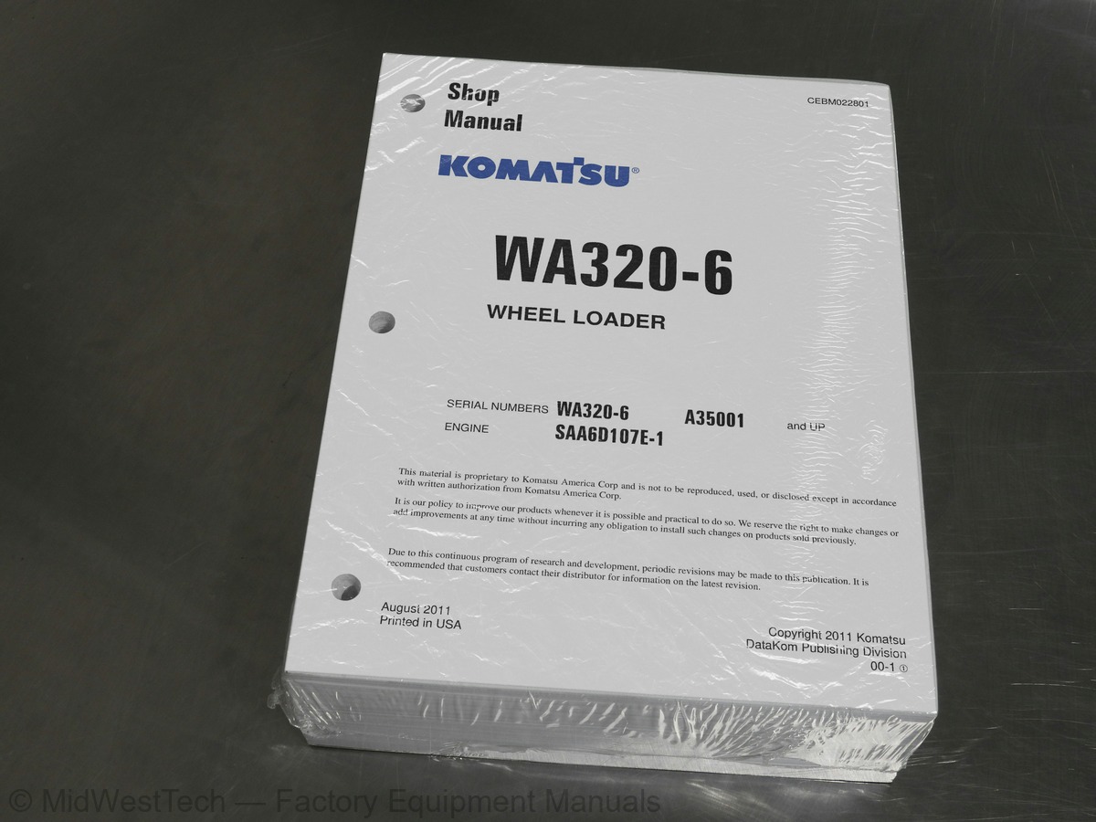
Komatsu WA320-6 with SAA6D107E-1 Engine Wheel Loader Service Manual
1,397 pages · Publication CEBM022801
Added to your cart. View cart
- Models
- WA320-6 with SAA6D107E-1 Engine
- Serial coverage
- A35001 and up
- Manual type
- Service Manual
- Pages
- 1,397
- Publication
- CEBM022801
- Condition
- Brand new
What's inside
From the manual's own table of contents: 5 sections, 563 entries. See sample pages (PDF, 868 KB)
FOREWORD8 topics
- 12CONTENTS
- GENERAL
- STRUCTURE, FUNCTION AND MAINTENANCE STANDARD
- STANDARD VALUE TABLES
- TESTING AND ADJUSTING
- TROUBLESHOOTING
- DISASSEMBLY AND ASSEMBLY
- DIAGRAMS AND SCHEMATICS
STRUCTURE, FUNCTION AND124 topics
- Front Differential
- Rear Differential
- Torque Proportioning Differential
- Limited Slip Differential (if equipped)
- Final Drive
- Front Final Drive
- Rear Final Drive
- STEERING SYSTEM
- Steering Piping Diagram
- Steering Column
- Priority Valve
- Orbitrol Valve
- Operation
- Connection of Hand Pump and Sleeve
- Cushion Valve
- Steering Cylinder
- Emergency Steering Piping Diagram (if equipped)
- Emergency Steering Valve (if equipped)
- Steering Relief Valve (if equipped)
- BRAKE SYSTEM
- Brake Piping Diagram
- Charge Valve
- Brake Valve
- Braking Operation
- Inching Valve
- Accumulator (for Brake)
- Slack Adjuster
- Brakes
- Front Brake
- Rear Brake
- Parking Brake System
- Brake Control
- Parking Brake
- UNDERCARRIAGE AND FRAME
- Axle Mounting and Center Hinge Pin
- Tires
- Radial Tire
- Bias Tire
- HYDRAULIC SYSTEM
- Work Equipment Hydraulic Piping Diagram
- Work Equipment Control Lever Linkage
- Multi-Function Mono-Lever Type
- 2-Lever Type (if equipped)
- Hydraulic Tank
- Breather
- 4-Gear Pump
- Work Equipment Control Valve
- 2-Spool Type
- 3-Spool Type
- Relief Valve
- Safety-Suction Valve
- Suction Valve
- Operation of Work Equipment Control Valve
- Cutoff Valve
- PPC Valve
- Work Equipment PPC Valve: Mono Lever Type
- Work Equipment PPC Valve: 2-Lever Type (if equipped)
- Attachment PPC Valve
- Lock Valve (for PPC Circuit)
- Accumulator (for PPC Circuit)
- ECSS Valve
- Accumulator (for ECSS)
- Work Equipment
- Work Equipment Linkage
- Bucket
- Bucket Positioner and Boom Kickout
- Operation of Proximity Switch
- Work Equipment Cylinders
- Lift Cylinder
- Bucket Cylinder
- CAB ENVIRONMENT
- Air Conditioner
- Air Conditioner Piping Diagram
- Refrigerant Circuit Diagram
- Air Conditioner Unit
- Blower and Intake Unit
- Compressor
- Condenser
- Receiver
- Air Conditioner Panel
- ELECTRICAL SYSTEM
- Machine Monitor System
- System Circuit Diagram
- Machine Monitor
- Items Displayed on Monitor
- Machine Monitor Operation Switches
- Setting Machine Monitor
- Troubleshooting Function
- Character Display Function
- Operator Mode Functions
- Service Mode Functions
- Input and Output Signals
- Electrical System (HST Controller System)
- Input and Output Signals Diagram
- HST Controller Gearshifting Control Function
- HST Controller Protection Function
- Cooling Fan Control Function
- HST Controller
- ECSS System
- ELECTRONIC TRANSMISSION CONTROL
- KOMTRAX Terminal System
- KOMTRAX Terminal
- Engine Starting Circuit
- Engine Stopping Circuit
- Preheating Circuit
- Engine Output Lowering Function
- Automatic Warm-up Function
- Parking Brake Circuit
- Max. Traction Switch (if equipped)
- Multi-Function Knob
- Modification of Multi-Function Lever
- Sensors
- Speed Sensor
- HST Oil Temperature Sensor
- Brake Oil Temperature Sensor
- HST Oil Pressure Sensor
- HST Oil Filter Clogging Sensor
- Coolant Level Sensor
- Fuel Level Sensor
- Accelerator Pedal Sensor
- Air Cleaner Clogging Sensor
- Water-in-Fuel Sensor
- Boom Kick-Out Proximity Switch
- Bucket Positioner Proximity Switch
TESTING AND ADJUSTING115 topics
- BELTS
- Air Conditioner Compressor Belt
- Testing the Tension
- Adjusting the Tension
- Replacing Alternator Belt
- ACCELERATOR PEDAL
- Testing Operating Effort
- Testing Operating Angle
- DIRECTIONAL LEVER
- Checking Operating Effort
- Checking Travel
- POWER TRAIN OIL PRESSURES
- HST Oil Pressure
- Testing High-Pressure Cutoff Oil Pressure
- Testing Low-Pressure Relief Pressure
- Testing Servo Piston Control Pressure (DA Pressure)
- Testing Servo Piston Actuating Pressure
- Adjusting High-Pressure Cutoff Valve
- Adjusting Low-Pressure Relief Valve
- Adjusting DA Pressure
- Testing Clutch Control Pressure
- Steering Wheel
- Measuring Play
- Measuring Operating Effort
- Measuring Operating Time
- Steering Oil Pressure
- Measuring Main Relief Pressure
- Adjusting Main Relief Pressure
- Bleeding Air from Steering Circuit
- HYDRAULIC DRIVE FAN
- Measuring Fan Speed
- Measuring Fan Drive Oil Pressure
- WHEEL BRAKE SYSTEM
- Measuring Pressing Angle of Brake Pedal
- Brake Pedal Linkage
- Testing
- Adjusting
- Measuring Brake Performance
- Accumulator Charge
- Measuring
- Measuring Brake Oil Pressure
- Testing Wear of Wheel Brake Disc
- Bleeding Air from Brake Circuit
- Releasing Residual Pressure in Brake Accumulator Circuit
- Testing Parking Brake Performance
- Parking Brake Control Cable
- WORK EQUIPMENT SYSTEM
- Work Equipment Control Lever
- Measuring Travel
- Work Equipment Hydraulic Pressure
- PPC Oil Pressure
- Measuring PPC Valve Basic Pressure
- Measuring PPC Valve Output Pressure
- Bleeding Air from Hydraulic Circuit
- Bleeding Air from Work Equipment PPC Circuit
- Bleeding Air from Cylinders
- Releasing Residual Pressure in Hydraulic Circuit
- Between Each Hydraulic Cylinder and Control Valve
- In Brake Accumulator Circuit
- In PPC Accumulator Circuit
- Work Equipment Positioners
- Bucket Positioner
- Boom Kickout Switch
- Proximity Switch Operation Pilot Lamp
- ELECTRICAL SYSTEM TROUBLESHOOTING
- Procedure for Testing Diodes
- When Using Digital Type Circuit Tester
- When Using Analog Type Circuit Tester
- Preparation for Troubleshooting Electric System
- Boost Pressure and Temperature Sensor (BOOST PRESS & IMT)
- Supply Pump IMV Solenoid (FUEL REGULATOR)
- Common Rail Pressure Sensor (FUEL RAIL PRESS)
- Engine Coolant Temperature Sensor (COOLANT TEMP)
- Terminal Installed at Plant Before Shipment
- Terminal Retrofitted Machine After Shipment
- Starting Operation
- Application for the Start of Use
- Komtrax Terminal Lamps
- Contents of 7-Segment and Dot Displays for CPU
- Adjusting Machine Monitor
- Adjusting for Replaced, Reassembled, or Added Sensor/Controller
- Adjustment for User’s Needs
- Special Functions of Machine Monitor (EMMS)
- Normal and Special Functions of Machine Monitor
- Functions and Flow of Service Mode
- Operator Mode
- Service Meter Display Function (1)
- Traction Level Selection Function (2)
- HST Function Selection Function (3)
- Odometer Display Function (4)
- Maintenance Monitoring Function (5)
- Telephone Number Input Function (6)
- Language Selection Function (7)
- Monitor Brightness Adjustment Function (8)
- Travel Speed/Engine Speed Display Selecting Function (9)
- Travel Speed/Engine Speed Display/Non-Display Selecting Function (10)
- Action Code Display Function (11)
- Failure Code Display Function (12)
- Service Mode
- Switching to Service Mode and Screen Display (1)
- Electrical System Fault History Display Function (ELECTRIC FAULT) (2)
- Mechanical System Fault History Display Function (MACHINE FAULT) (3)
- Real-Time Monitoring Function (REAL-TIME MONITOR) (4)
- Real-Time Monitoring Code Tables
- Engine Reduced-Cylinder Function (CYLINDER CUT-OUT) (5)
- No-Injection Cranking Function (6)
- Adjustment Function (TUNING) (7)
- Maintenance Monitoring Function (8)
- Operating Information Display Function (9)
- Optional Device Selecting Function (10)
- Machine Serial Number Input Function (11)
- Model Select Function (MACHINE WA***) (12)
- Initialize Function (13)
- Setting Procedure for Service Meter and Odometer
- PM-CLINIC INSPECTION TABLE
TROUBLESHOOTING277 topics
- CANNON Connectors for Engine
- AMP Connectors for Engine
- FRAMATOME Connectors for Engine
- PACKARD Connectors for Engine
- OT Series Connectors for Engine
- T-BRANCH BOX and T-BRANCH ADAPTER TABLE
- MODE CHART
- INFORMATION CONTAINED IN TESTING PROCEDURES
- TROUBLESHOOTING BY FAILURE CODE
- Failure Code Table
- FUSE BOX AND SLOW-BLOW FUSES
- Connection Table of Fuse Box and Slow-Blow Fuses
- Fuse Box: FS1
- Fuse Box: FS2
- Slow-Blow Fuses
- FAILURE CODES
- Brake: Oil Pressure Reduction
- HST Filter: Clogging
- Travel Speed: Overrun Alarm
- AA1ANX
- Air Cleaner: Clogging
- Alternator R System: Hot Short
- AB00MA
- Alternator R System: Ground Fault/Disconnection/Low Charge Voltage
- B@BAZG
- Engine: Oil Pressure Reduction
- B@BAZK
- Engine Oil: Low Level
- B@BCNS
- Engine: Overheat
- B@BCZK
- Engine: Low Coolant Level
- B@C6NS
- Front Brake: High Oil Temperature
- B@CRNS
- HST: High Oil Temperature
- Abnormality in Engine Controller
- Engine Ne or Bkup Speed Sensor Error
- Charge Pressure Sensor High Error
- Charge Pressure Sensor Low Error
- Throttle Sensor High Error
- Throttle Sensor Low Error
- Coolant Sensor High Error
- Coolant Sensor Low Error
- Charge Temperature Sensor High Error
- Charge Temperature Sensor Low Error
- Lowering of Speed by Abnormally High Charge Temperature
- Sensor Power Supply 2 Low Error
- Atmospheric Pressure Sensor High Error
- Atmospheric Sensor Low Error
- Sensor Power Supply 2 High Error
- Engine Overspeed
- Ne Speed Sensor Power Supply Error
- IMV (IMA) Short Circuit
- IMV (IMA) Disconnection
- Injector #1 Open/Short Error
- Injector #5 Open/Short Error
- Injector #3 Open/Short Error
- Injector #6 Open/Short Error
- Injector #2 Open/Short Error
- Injector #4 Open/Short Error
- Calibration Code Inconsistency
- Injectors Drive Circuit Error
- Sensor Power Supply 1 Low Error
- Sensor Power Supply 1 High Error
- Abnormally High Level in Water Sensor
- Abnormally Low Level in Water Sensor
- Idle Validation Switch Error
- Idle Validation Action Error
- Engine Oil Pressure Switch Error
- Battery Voltage Low Error
- Battery Voltage High Error
- Common Rail Pressure High Error 2
- Common Rail Pressure Sensor High Error
- Common Rail Pressure Sensor Low Error
- Lowering of Torque by Abnormally High Charge Temperature
- Common Rail Pressure High Error 1
- Supply Pump Pressure Very Low Error
- Engine Ne Speed Sensor Error
- Engine Bkup Speed Sensor Phase Error
- All Continuous Data Lost Error
- Engine Bkup Speed Sensor Error
- KOMNET Datalink Timeout Error
- Throttle Sensor Supply Voltage High Error
- Throttle Sensor Power Supply Low Error
- Supply Pump Pressure Very Low Error 2
- Abnormality in IMV (IMA) Solenoid
- Intake Heater Relay Disconnection Error
- Intake Heater Relay Short Circuit Error
- Backup Alarm/Lamp Relay 1 Circuit: Hot Short
- ECSS Solenoid Relay: Hot Short
- D1B0KA
- HST Safety Relay: Disconnection
- D1B0KB
- HST Safety Relay: Ground Fault
- D1B0KY
- HST Safety Relay: Hot Short
- D5ZHL6
- IGN C System: Ground Fault/Disconnection
- DAF3KK
- UNSW Power Supply: Ground Fault/Disconnection
- DAFRKR
- Machine Monitor CAN-NET Signal: Disconnection
- DAJ0KK
- HST Controller Power Supply: Low Voltage
- DAJ0KT
- HST Controller Memory (EEPROM): Abnormality
- DAJ1L4
- HST Controller Main Power Line: Disconnection/Ground Fault
- DAJ1L6
- HST Controller Main Power Line: Hot Short
- DAJ2KK
- Controller Solenoid Power Supply: Low Voltage
- DAJ2L3
- HST Controller Load Power Supply Holding Line: Hot Short in Wiring Harness
- DAJ2L4
- HST Controller Load Power Supply Holding Line: Disconnection/Ground Fault
- DAJ5KX
- Sensor 5V Power Supply: Out-of-Output Range
- DAJ9KQ
- HST Controller Model Selection: Disagreement of Model Selection Signals
- DAJRKR
- HST Controller CAN-NET Signal: Disconnection
- DAJRMA
- HST Controller: Disagreement in Option Selection
- DB2RKR
- Engine Controller CAN-NET: Disconnection in Signal Line
- DD1NL4
- Fan Automatic Reverse Switch Signal: Abnormality
- DD1NLD
- Fan Reverse Switch Signal: Abnormality
- DDB6KA
- Parking Brake Reminder Signal: Disconnection/Short Circuit
- DDB6KB
- Parking Brake Indicator Signal: Ground Fault
- DDB6KZ
- Parking Brake Switch or Parking Brake Reminder Switch: Trouble
- DDB6L0
- Parking Brake Reminder Signal: Ground Fault
- DDB6L4
- Parking Brake Indicator Signal: Disconnection/Hot Short
- DDD7KX
- Travel Speed Control Dial Signal: Disconnection/Ground Fault
- DDD7KY
- Travel Speed Control Dial Signal: Hot Short
- DDE5MA
- Emergency Steering Operation Switch: Disconnection
- DDK3KA
- Directional Selector Switch: Disconnection/Hot Short
- DDK3KB
- Directional Selector Switch: Ground Fault
- DDK6KA
- FNR Lever: Disconnection/Ground Fault
- DDK6KY
- FNR Lever: Hot Short
- DDS5L6
- Steering: Low Oil Pressure (Operation of Emergency Steering)
- DF10KA
- Travel Speed Range Selector Switch: Disconnection/Ground Fault
- DF10KB
- Travel Speed Range Selector Switch: Hot Short
- DGH1KX
- HST Oil Temperature Sensor: Ground Fault
- DGR2KB
- Brake Oil Temperature Sensor: Ground Fault
- DGR2KZ
- Brake Oil Temperature Sensor: Disconnection/Hot Short
- DHH1KX
- HST Oil Pressure Sensor: Disconnection/Ground Fault
- DHH1KY
- HST Oil Pressure Sensor: Hot Short
- DHTCL6
- HST Filter Clogging Sensor: Functional Defect
- DJF1KA
- Fuel Level Sensor: Disconnection/Hot Short
- DLT3KX
- Travel Speed Sensor B: Abnormality
- DLT4KX
- Travel Speed Sensor A: Abnormality
- DLT4LC
- Travel Speed Sensor A & B: Abnormality
- DV00KY
- Alarm Buzzer: Hot Short
- DW26KA
- Motor 2 Solenoid: Disconnection/Ground Fault
- DW26KY
- Motor 2 Solenoid: Hot Short
- DW7BKY
- Fan Reverse Solenoid Circuit: Hot Short
- DW7BKZ
- Fan Reverse Solenoid Circuit: Disconnection/Ground Fault
- DX16KA
- Fan EPC Solenoid: Disconnection
- DX16KB
- Fan EPC Solenoid: Ground Fault
- DX16KY
- Fan EPC Solenoid: Hot Short
- DX19KA
- Motor 1 Solenoid: Disconnection
- DX19KB
- Motor 1 Solenoid: Ground Fault
- DX19KY
- Motor 1 Solenoid: Hot Short
- DX20KA
- Clutch EPC Solenoid: Disconnection
- DX20KB
- Clutch EPC Solenoid: Ground Fault
- DX20KY
- Clutch EPC Solenoid: Hot Short
- DXH7KB
- Reverse Solenoid: Ground Fault
- DXH7KZ
- Reverse Solenoid: Disconnection/Hot Short
- DXH8KB
- Forward Solenoid: Ground Fault
- DXH8KZ
- Forward Solenoid: Disconnection/Hot Short
- Steering Pump: Overrun Alarm
- HST Pump: Overrun Alarm
- Motor 1: Overrun Alarm
- TROUBLESHOOTING: E-MODE
- Troubleshooting Electrical System
- Information in Troubleshooting Table
- Engine Does Not Start
- Preheater Does Not Operate Manually
- Travel Speed is Low or High
- ECSS Does Not Operate
- ECSS Keeps Operating
- Defective Boom Kickout Function and Cancellation
- Defective Bucket Positioner Function and Cancellation
- Defective Lift Arm FLOATING Holding Function and Cancellation
- Travel Direction Selection System Does Not Function
- Fan Does Not Reverse
- Fan Keeps Rotating in Reverse
- Wiper Does Not Operate
- Windshield Washer Does Not Operate
- Headlamp, Clearance Lamp, and Tail Lamp Do Not Light Up or Go Off
- Working Lamp Does Not Light Up or Go Off
- Turn Signal Lamp and Hazard Lamp Do Not Light Up or Go Off
- Brake Lamp Does Not Light or It Keeps Lighting Up
- Backup Lamp Does Not Light or It Keeps Lighting Up
- Backup Alarm Does Not Sound or It Keeps Sounding
- Horn Does Not Sound or It Keeps Sounding
- Alarm Buzzer Does Not Sound or It Keeps Sounding
- Air Conditioner Does Not Operate or Stop
- The KOMTRAX System Does Not Work Properly
- Lamp Display Section of KOMTRAX Terminal
- TROUBLESHOOTING: H-MODE
- Troubleshooting Hydraulic and Mechanical Systems
- Method of Using Troubleshooting Chart
- Table of Failure Codes and Causes
- Machine Does Not Start
- Travel Speed Is Slow
- Traction Force Is Weak
- Engine Stalls When Traveling or Engine Speed Drops Excessively
- Shift Range is Not Shifted
- Steering Wheel Does Not Turn
- Steering Wheel Is Heavy
- Steering Wheel Shakes or Jerks
- Machine Deviates Naturally to One Side When Traveling
- Brake Does Not Work or Does Not Work Well
- Brake Is Not Released or Is Dragged
- Lift Arm Does Not Rise or Lower
- Lift Arm Moves Slowly or Lift Arm Rising Force Is Insufficient
- When Rising, Lift Arm Starts to Move Slowly at a Specific Height
- Lift Arm Cylinder Cannot Hold Down The Bucket (Bucket Rises in the Air)
- Hydraulic Drifts of the Lift Arm Occur Often
- Lift Arm Wobbles During Operation
- Bucket Does Not Tilt Back
- Bucket Moves Slowly or Tilting-Back Force Is Insufficient
- Bucket Starts to Operate Slowly in the Midst of Tilting Back
- Bucket Cylinder Cannot Hold Down the Bucket
- Hydraulic Drifts of the Bucket Occur Often
- Bucket Wobbles During Travel with Load
- Control Levers of Lift Arm and Bucket Do Not Move Smoothly and Are Heavy
- ECSS Does Not Operate and Machine Pitches and Bounces
- Fan Revolution Is Abnormal
DISASSEMBLY AND ASSEMBLY34 topics
- Engine Front Oil Seal Assembly
- Removal
- Installation
- Engine Rear Oil Seal Assembly
- Cooling Fan and Fan Motor Assembly
- Fuel Tank Assembly
- POWER TRAIN
- Transfer
- Transfer Assembly
- Disassembly
- Assembly
- Parking Brake Assembly
- Front Axle Assembly
- Rear Axle Assembly
- Axle Housing Assembly
- Differential Assembly
- Center Hinge Pin
- Counterweight
- HST Pump and 4-Gear Pump Assembly
- HST Pump Assembly
- WASTE HANDLER GUARDS
- Hydraulic Tank Guard
- Rear Light Guards
- Front Light Guards
- Front Step
- Axle Seal Guards
- Boom Cylinder Hose Guards
- Front Frame Underguard
- Fuel Tank Guard
- Rear Frame Underguard
- WASTE HANDLER SCREENS
- Lower Engine Baffle
- Hood Screen
- Exhaust Cover
Inside this manual
Real pages from this service manual (1,397 pages). Open the sample pages (PDF, 867 KB)
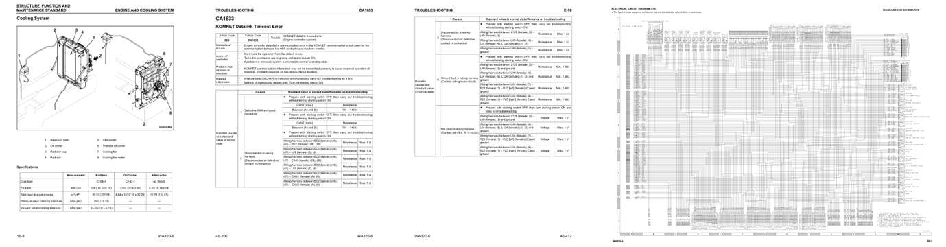
- Specifications, page 79: STRUCTURE, FUNCTION AND
- Troubleshooting, page 751: KOMNET Datalink Timeout Error
- Diagram, page 982: Possible
- Foldout diagram, page 1,385: DIAGRAMS AND SCHEMATICS
This is a service manual
Here's how it compares to the other manual types.
Service manual
Factory repair procedures and technical information such as specifications, troubleshooting, and wiring and hydraulic diagrams, for the models and systems the manual covers. See What's inside for its topics.
Operator's manual
Safe operation, controls, maintenance schedules, lubrication points, inspections, and basic checks. Repair procedures are in the service manual.
Parts manual
Illustrated diagrams with factory part numbers for identifying components and ordering parts. Repair procedures are in the service manual.
Engine service manuals are sometimes sold separately, since certain machine models were offered with more than one engine option.
What it's used for
Factory manual for in-house farm and construction shop use. Straightforward, complete, and easy to follow. It contains the OEM information dealership service departments and parts counters use to diagnose problems, identify components, and perform maintenance or repairs correctly.
Service shops and owner/operators who repair their own equipment
Identifying correct parts and seeing how assemblies come apart and go back together
Keeping equipment running with less downtime
Factory manual, 1,397 pages
Quantity one is the manual described above.
Fast free USA shipping
Ships in 1 business day.
60-day returns
Free if the mistake is ours. A manual ordered in error must come back unopened in its shrink-wrap; you pay return shipping and a 20% restocking fee applies. Return policy
Binder not included
Manuals over about 300 pages may need a standard 3-ring binder, which you can buy locally to keep the pages organized for shop use.
Other editions and similar models
Questions about model, serial number, engine coverage or contents? Contact us before purchasing and we'll help confirm it's the right manual. Please verify the manual type, machine model, serial number range and engine coverage before purchasing: manuals ordered in error carry a 20% restocking fee (return policy).